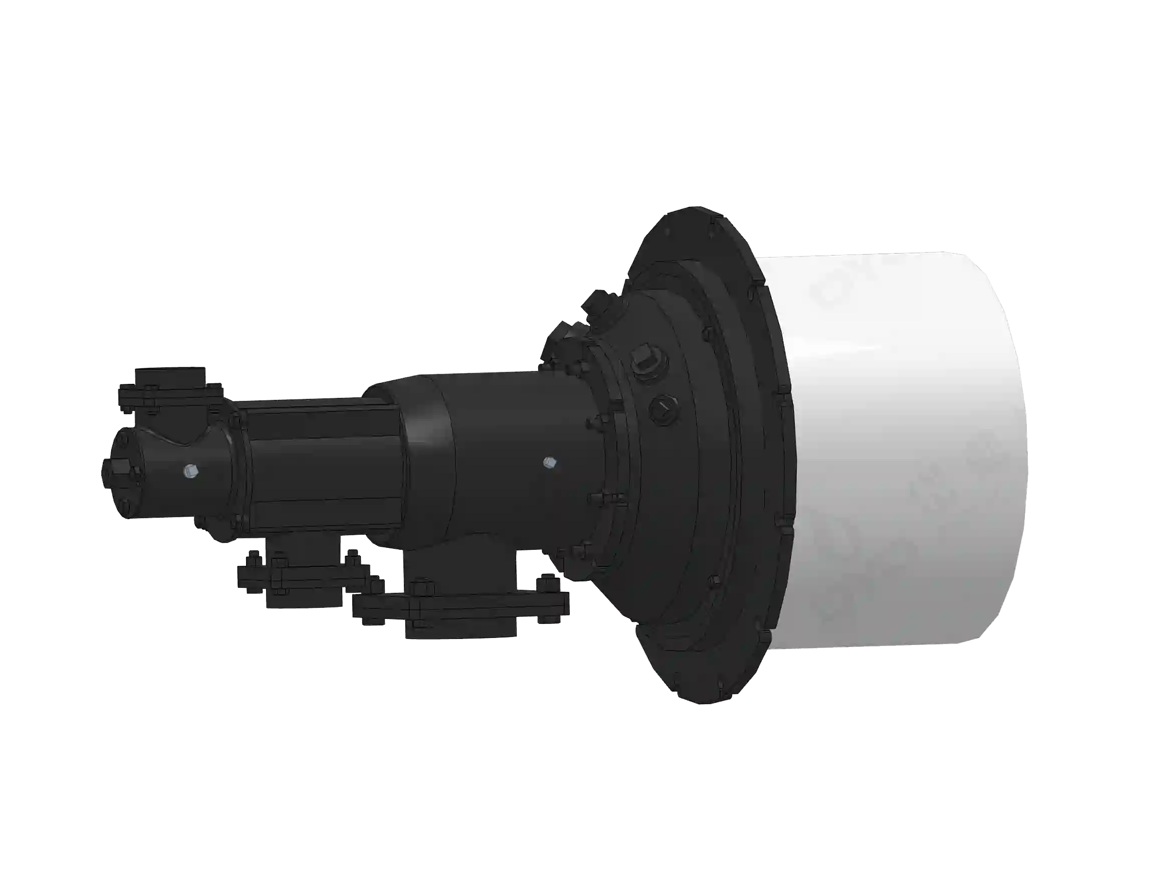
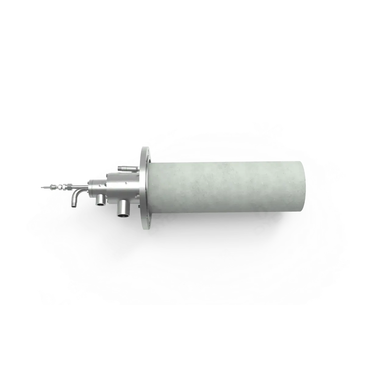
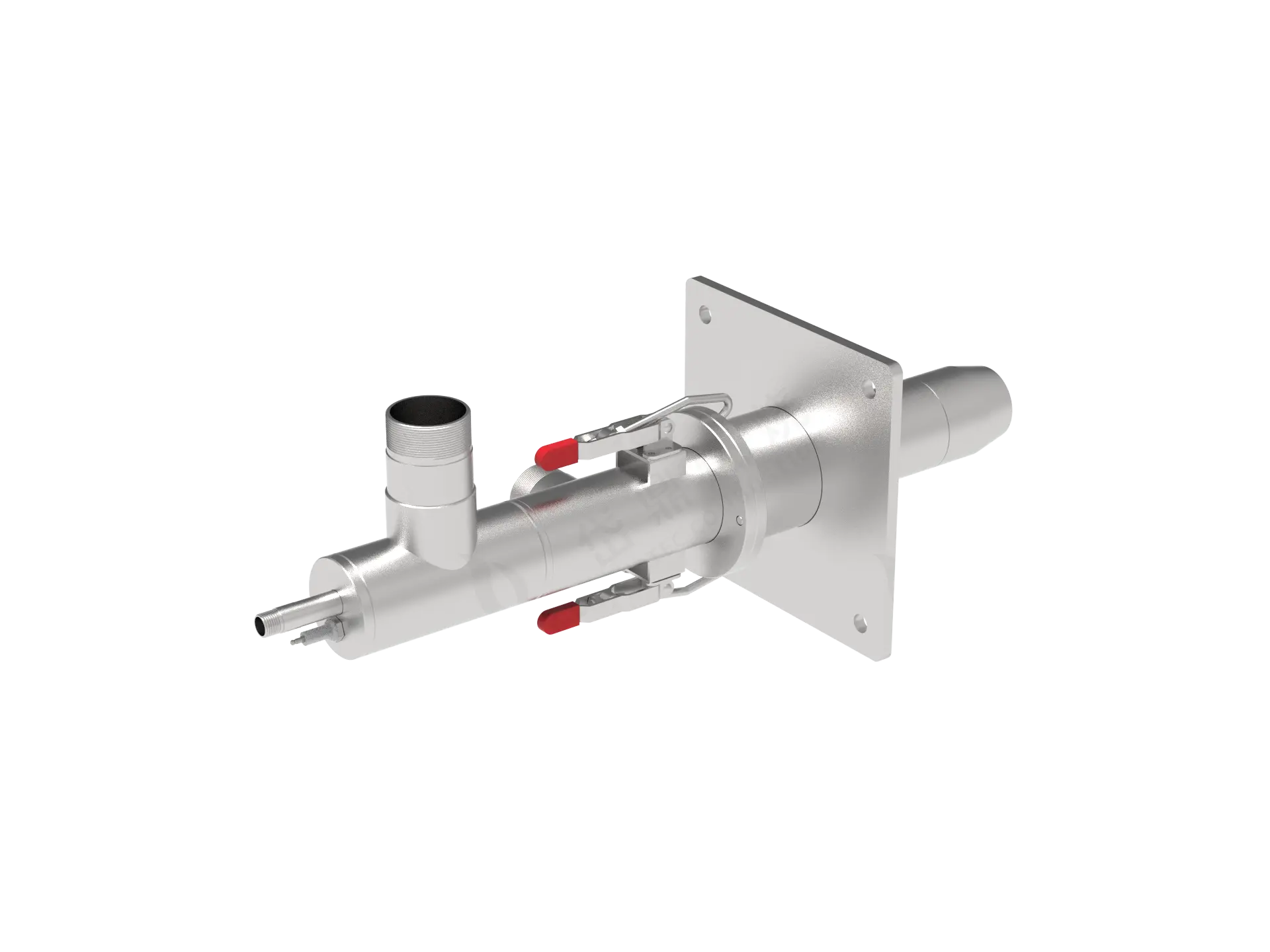
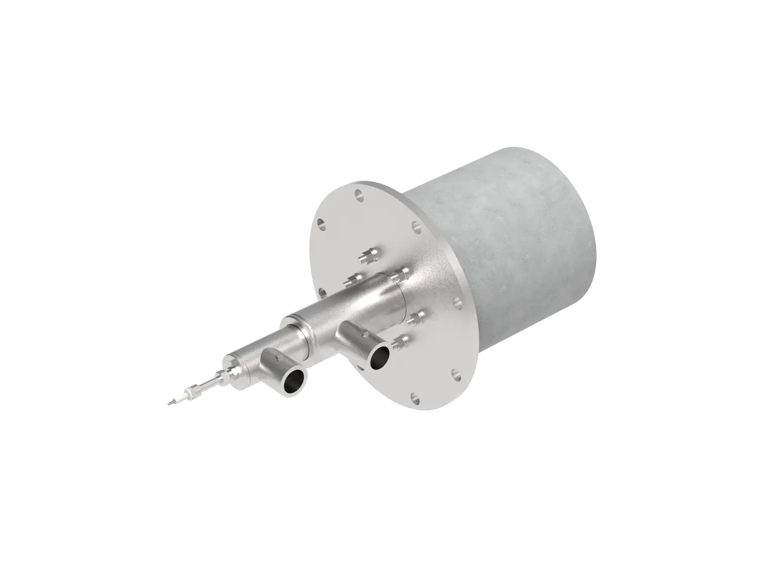
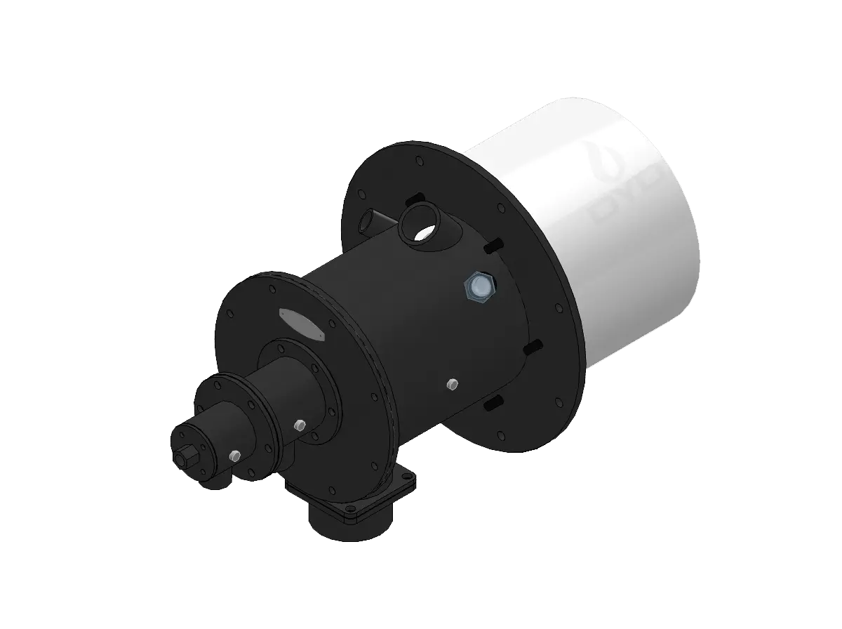
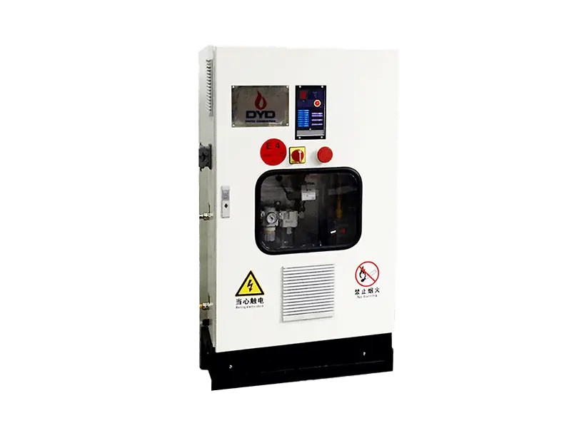
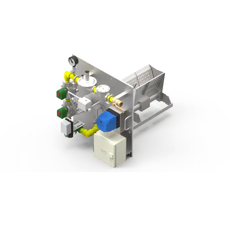
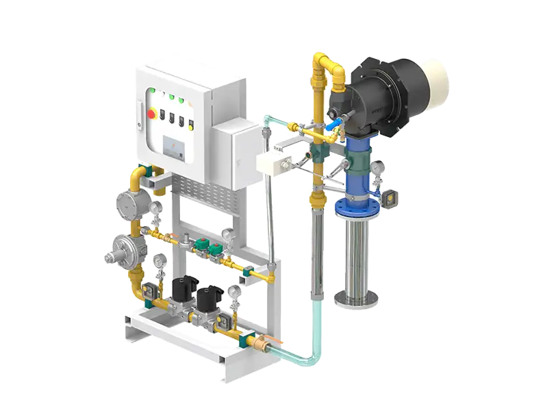
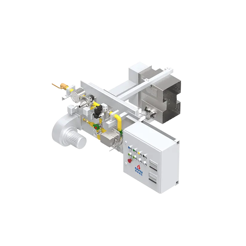
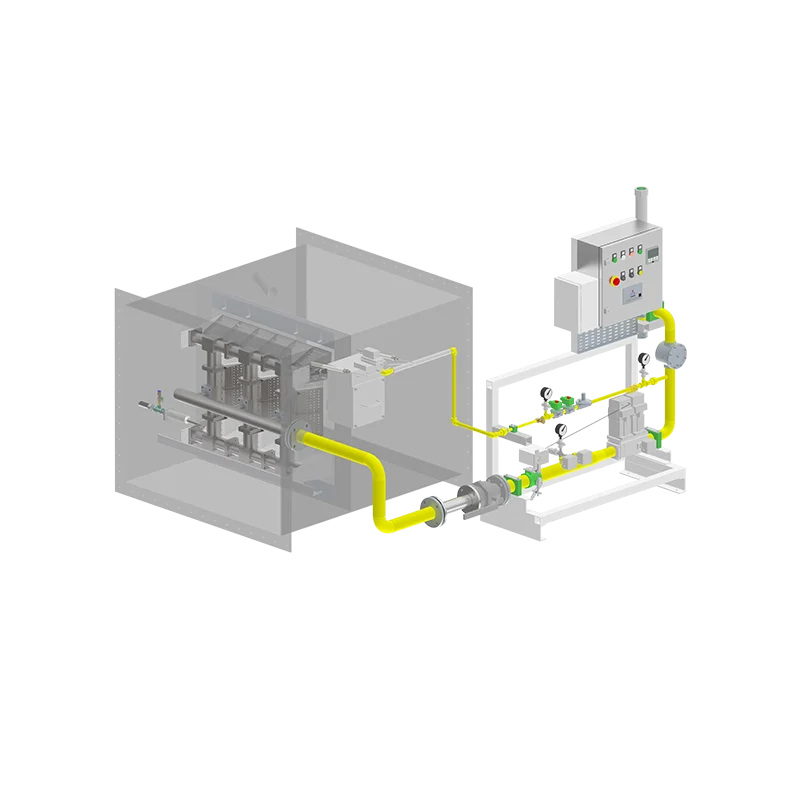
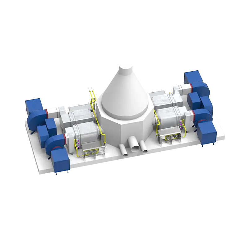
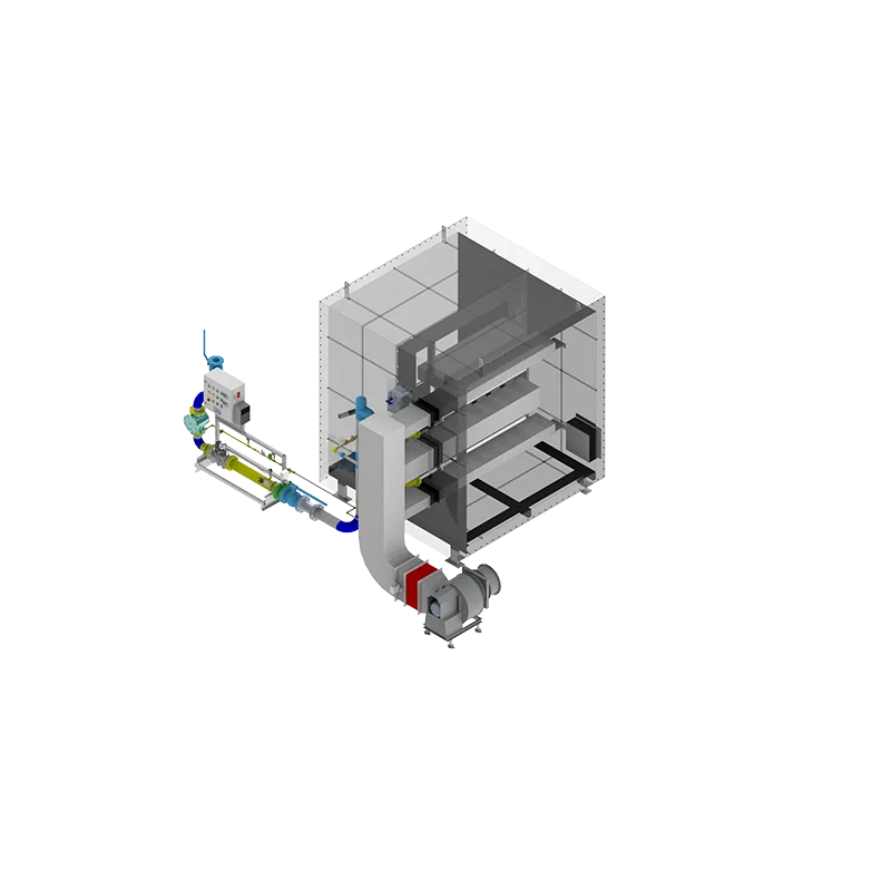
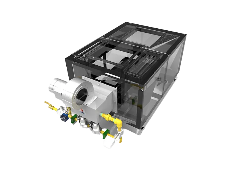
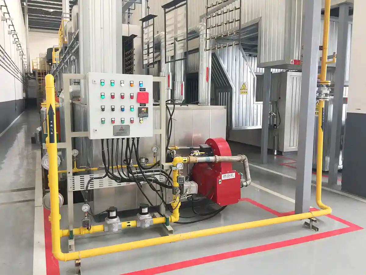
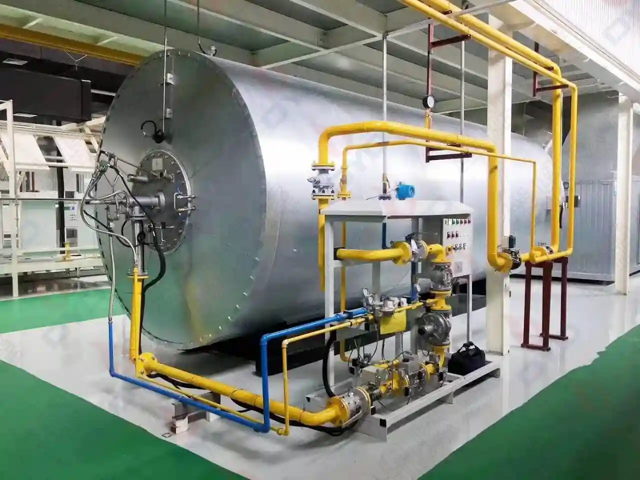
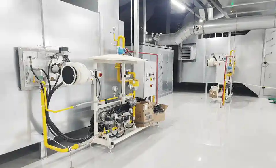
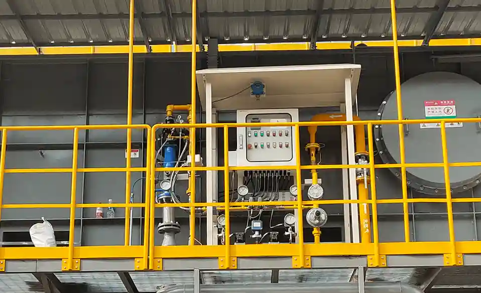
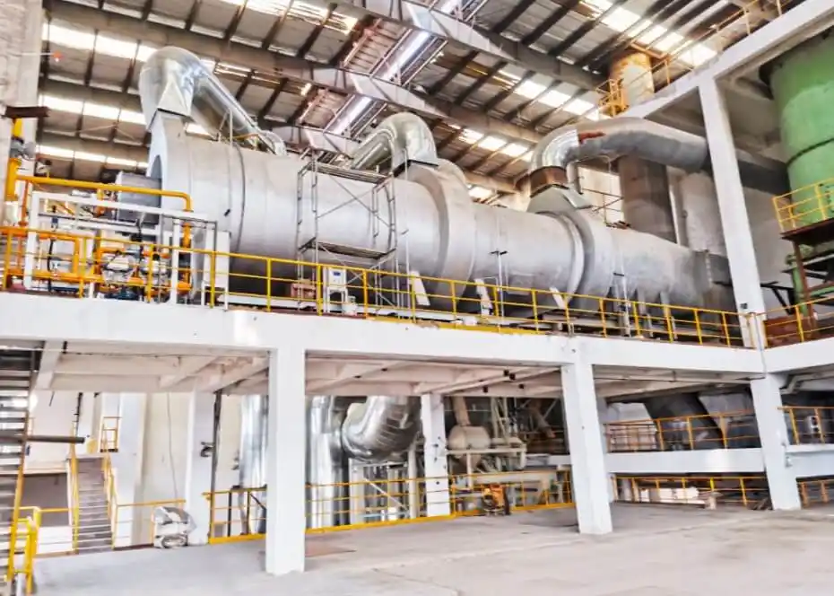
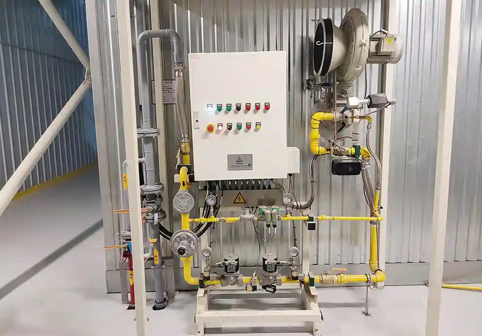
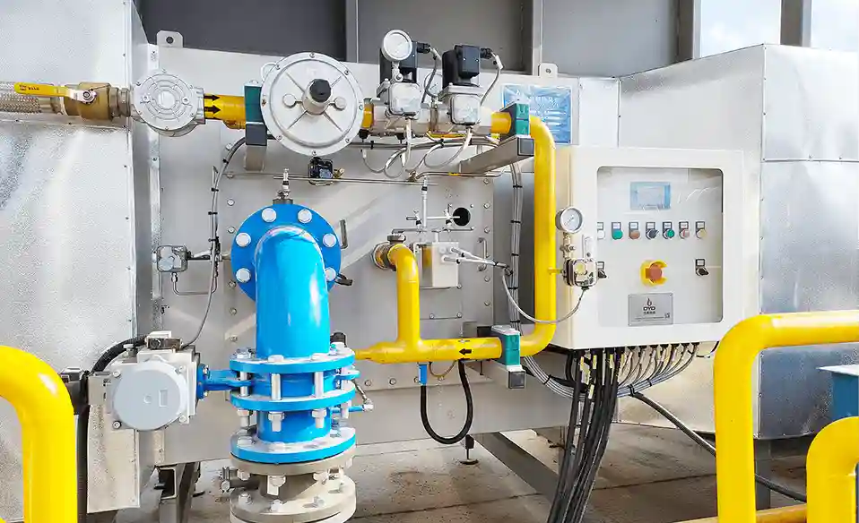
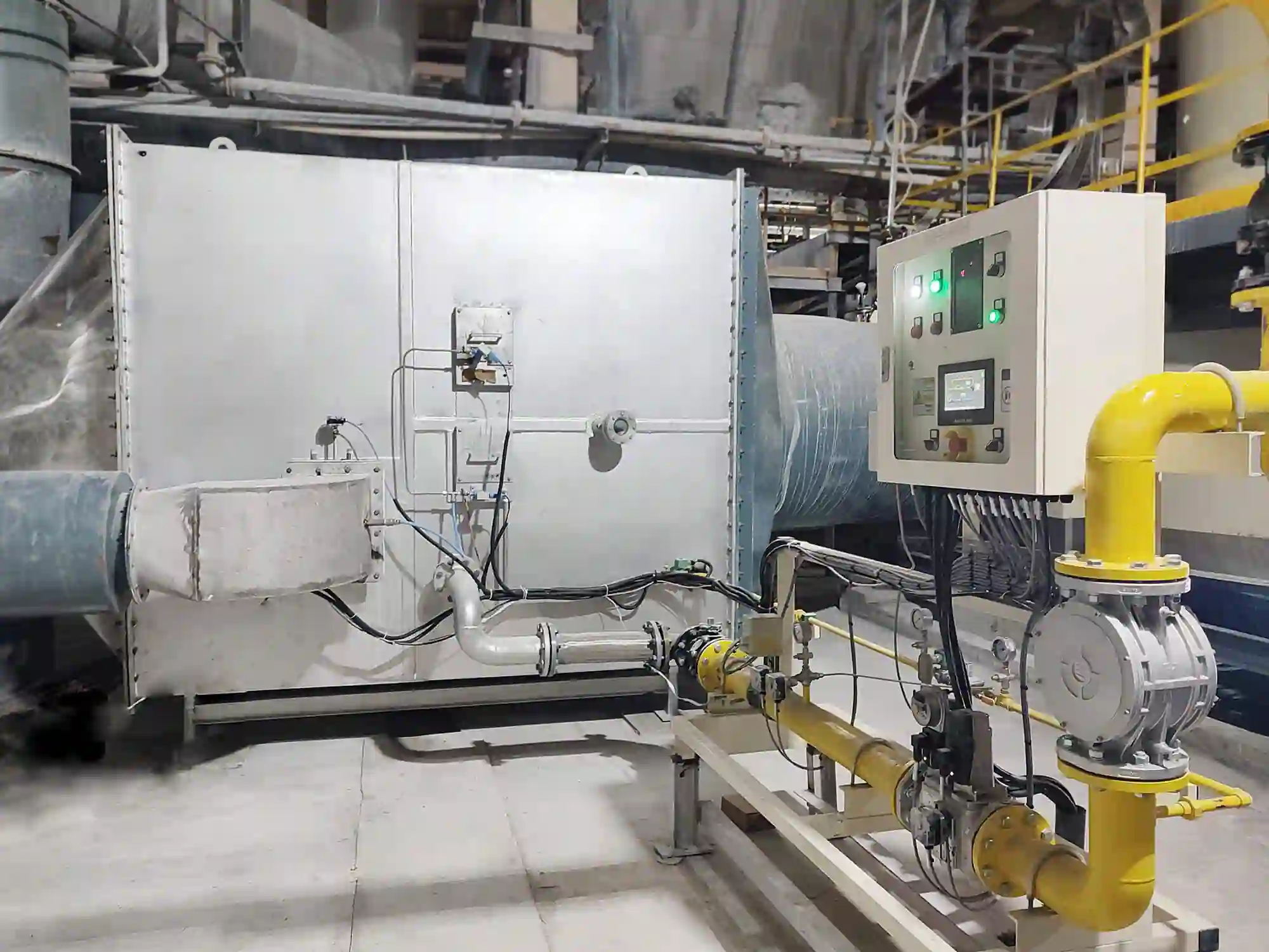
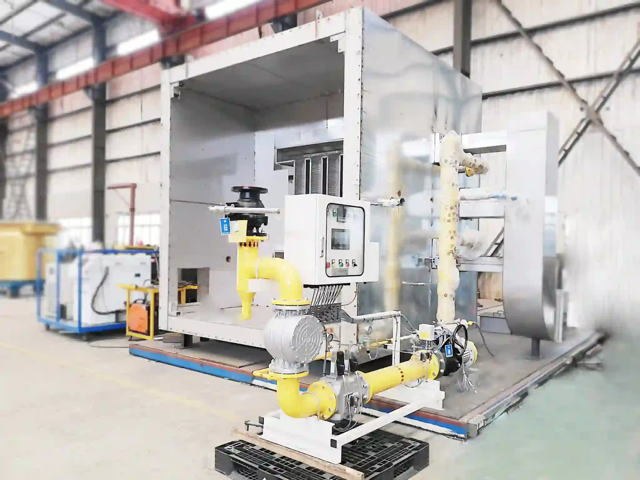
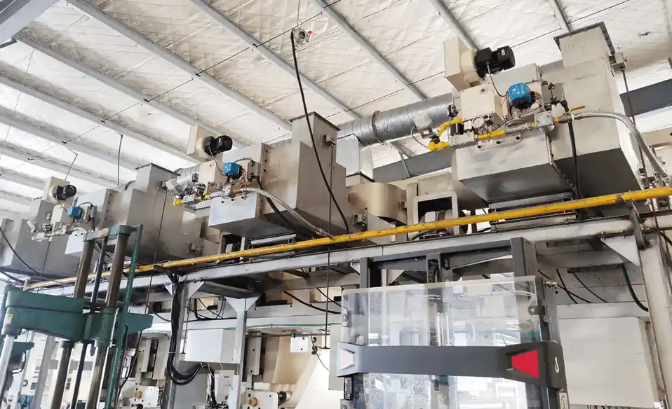
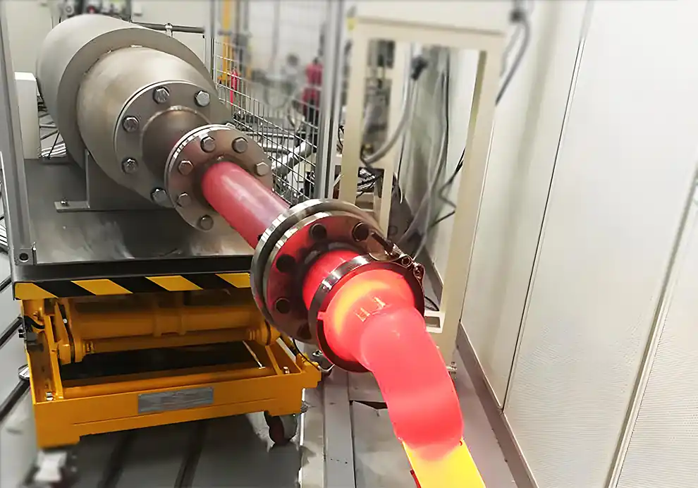
Integrating a burner into OEM equipment is much more than mounting a burner onto a machine and connecting a gas pipe.
For an OEM manufacturer, the burner becomes part of the equipment's complete thermal system. Its performance is closely connected to the combustion chamber, process airflow, fuel supply, exhaust system, temperature-control strategy, PLC, safety system, and production process.
A well-integrated burner should therefore satisfy several requirements simultaneously:
Deliver the required thermal capacity
Match the furnace or chamber geometry
Produce the appropriate flame shape and momentum
Operate across the required load range
Communicate correctly with the equipment control system
Meet the required safety functions
Allow practical maintenance
Remain stable under actual process conditions
The fundamental principle is:
The burner should be designed as part of the OEM equipment, not treated as an independent component.
Burner integration means connecting the burner with the mechanical, thermal, fuel, air, electrical, control, and safety systems of the OEM machine.
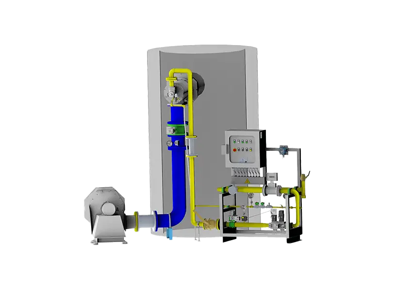
A typical integrated combustion system may include:
Fuel Supply
→
Burner
→
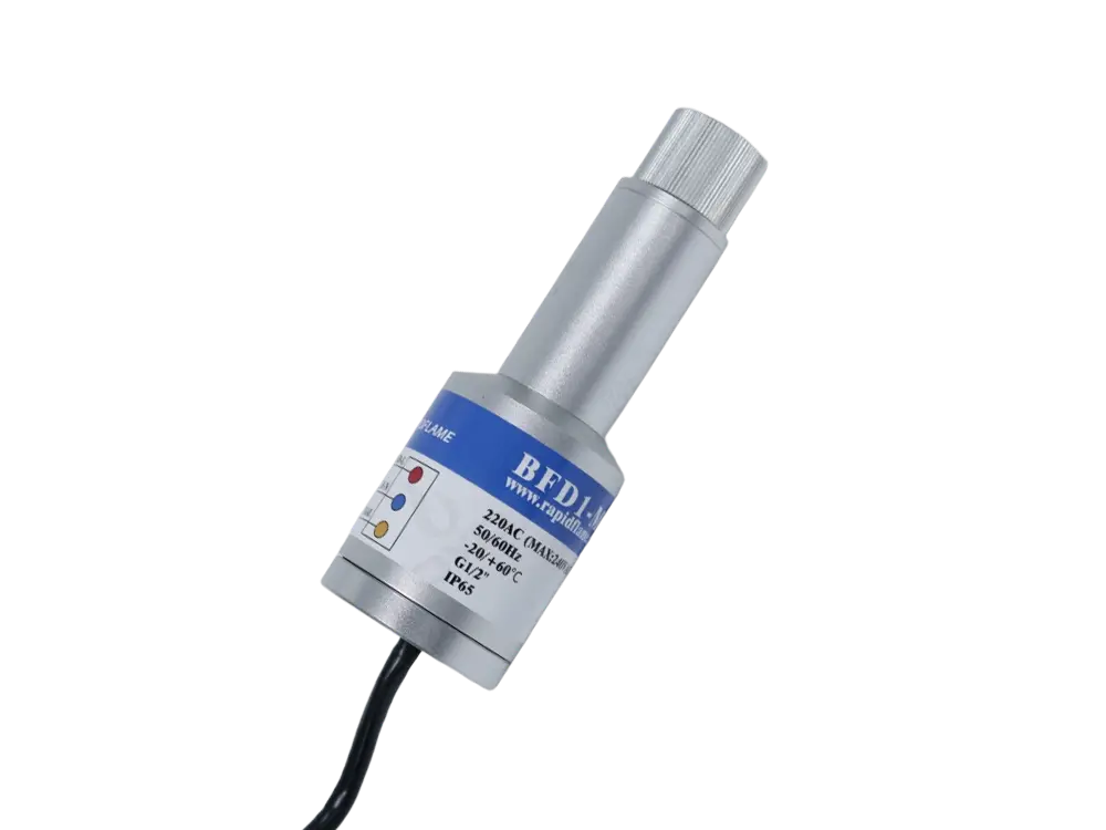
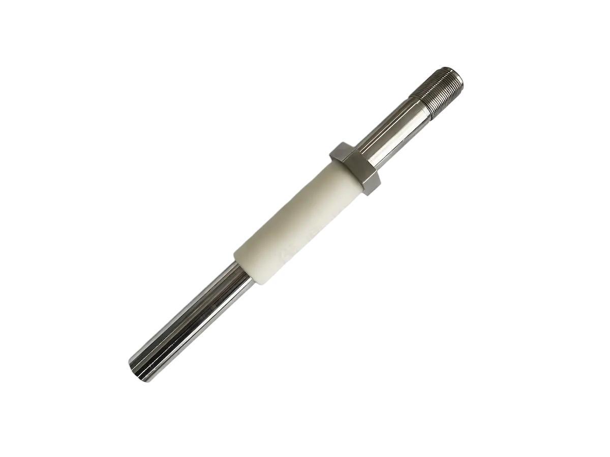
Ignition & Flame Detection
→
Combustion Chamber
→
Heat Transfer
→
Exhaust
while the control layer manages the entire process:
Temperature Sensor → PLC/PID → Burner Control → Heat Output
This means the burner needs to work correctly not only as a combustion device but also as a component within the machine's control and safety architecture.
Installing a burner primarily involves mechanical mounting and connecting utilities.
Integrating a burner requires much more.
An OEM manufacturer needs to determine:
Where the burner should be installed
What flame shape is required
How much combustion air is available
What fuel pressure is available
How the burner should modulate
How the burner communicates with the PLC
What happens during flame failure
How furnace pressure is controlled
How combustion gases move through the equipment
How the burner can be accessed for maintenance
For this reason, a burner that works well in one machine may not automatically work well in another machine with a similar thermal capacity.
The first step is to understand what the equipment actually needs to accomplish.
Important parameters include:
Operating temperature
Heating rate
Maximum heat demand
Minimum heat demand
Product throughput
Product temperature
Moisture load
Heat loss
Required temperature uniformity
Operating cycle
Continuous or intermittent operation
The burner should be selected based on the actual thermal requirement rather than simply choosing a standard burner based on equipment size.
For example, two drying machines may have the same chamber volume but completely different burner requirements because their product moisture, throughput, inlet temperature, and exhaust conditions are different.
Burner capacity should be determined from the equipment's thermal balance.
A simplified heat requirement can be considered as:
Required Burner Heat = Product Heating + Moisture Evaporation + Equipment Heat Loss + Exhaust Losses + Other Process Heat
The calculation should also consider the required safety margin and operating range.
The maximum burner capacity is important, but so is the minimum stable firing rate.
A burner that is correctly sized at maximum load may still be unsuitable if its minimum output is too high for the equipment's normal operating range.
Before selecting the burner, examine the physical space where combustion will occur.
Important dimensions include:
Chamber length
Chamber width
Chamber height
Burner opening
Burner insertion depth
Refractory thickness
Product position
Internal structures
Exhaust location
Available maintenance space
The geometry determines how the flame can develop.
For example:
Compact chamber + long flame
may result in flame impingement.
Meanwhile:
Large chamber + short concentrated flame
may create insufficient heat coverage.
Burner selection therefore needs to consider both thermal capacity and flame geometry.
Different OEM equipment requires different combustion technologies.
These are suitable for many applications involving direct or indirect industrial heating.
Typical applications include:
Furnaces
Ovens
Dryers
Heat-treatment equipment
Preheating systems
Industrial heating chambers
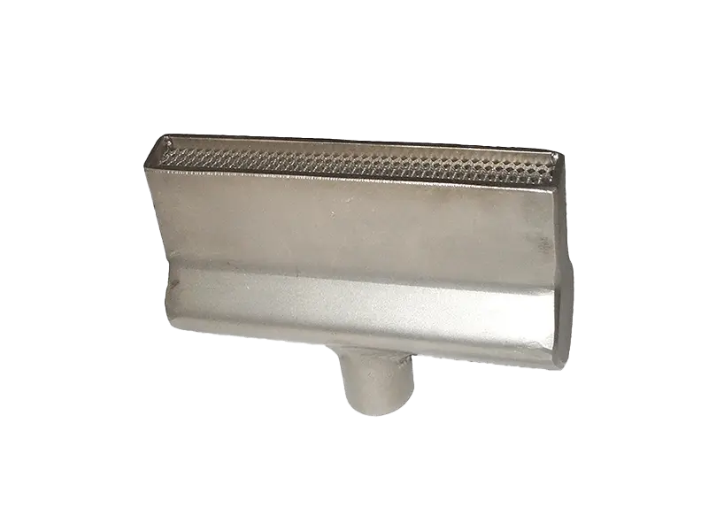
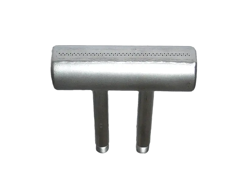
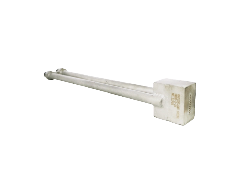
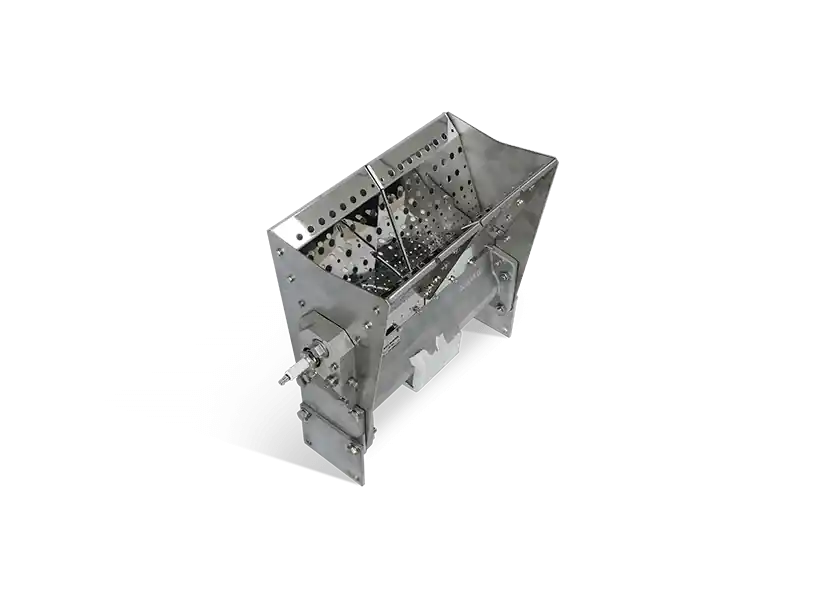
Linear burners are useful when heat needs to be distributed across a relatively large air or duct cross-section.
They can be particularly useful for:
Hot-air systems
Industrial dryers
Air heaters
Drying ovens
Continuous-process equipment
Low-NOx burners are appropriate when emission performance is an important equipment requirement.
The combustion technology needs to be matched to the furnace temperature, chamber geometry, fuel, and operating conditions.
Oxygen combustion may be considered when the process requires high heat intensity, reduced nitrogen ballast, or specific combustion conditions.
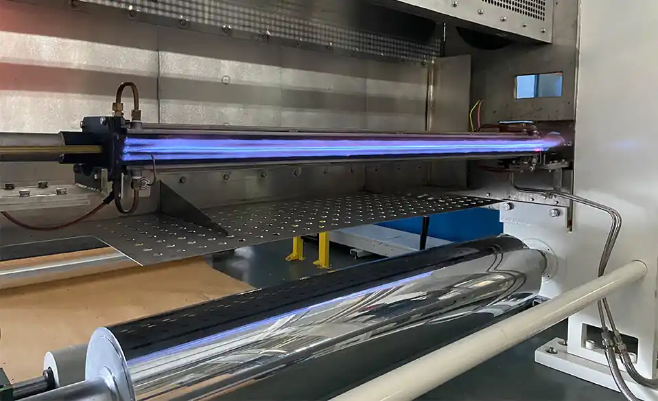
These are designed for applications where controlled flame exposure to a material surface is part of the production process.
Some OEM equipment requires burners designed around hydrogen, low-calorific-value gas, industrial off-gas, or other non-standard fuels.
The correct burner type is therefore determined by the process + equipment + fuel + thermal requirement, rather than by burner capacity alone.
One of the most important parts of burner integration is matching the flame characteristics to the chamber.
Important parameters include:
Flame length
Flame diameter
Flame velocity
Flame momentum
Heat-release profile
Flame temperature
Gas recirculation
Chamber temperature
The flame should have enough space to develop without causing excessive heat concentration.
Potential problems include:
The flame may contact:
Furnace walls
Refractory
Workpieces
Internal components
The heat may remain concentrated near the burner, resulting in poor temperature distribution.
Excessive momentum may cause unwanted impingement or unstable thermal distribution.
The flame may not penetrate sufficiently into a large chamber.
This is why flame characteristics should be considered during OEM equipment design.
The burner opening and mounting interface should be defined before the equipment structure is finalized.
Typical interface requirements include:
Mounting flange
Bolt pattern
Burner throat
Burner insertion depth
Gas connection
Air connection
Ignition connection
Flame detector position
Maintenance clearance
A standardized interface can make OEM production easier because the same burner configuration can be integrated into multiple equipment models.
For customized equipment, however, the burner interface may need to be adapted to the machine.
DYDTEC Combustion has 100+ burner models, allowing OEM engineers to select from a broad range of combustion configurations before moving to a customized solution.
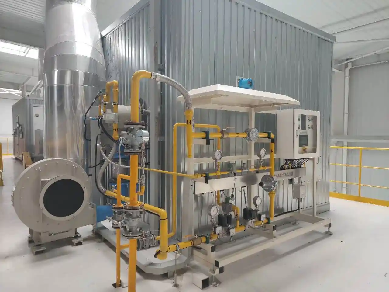
The burner needs a stable and properly controlled fuel supply.
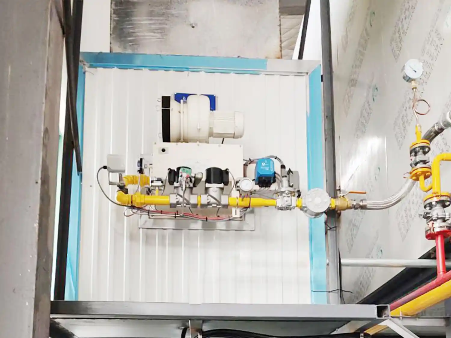
Depending on the application, the fuel system may include:
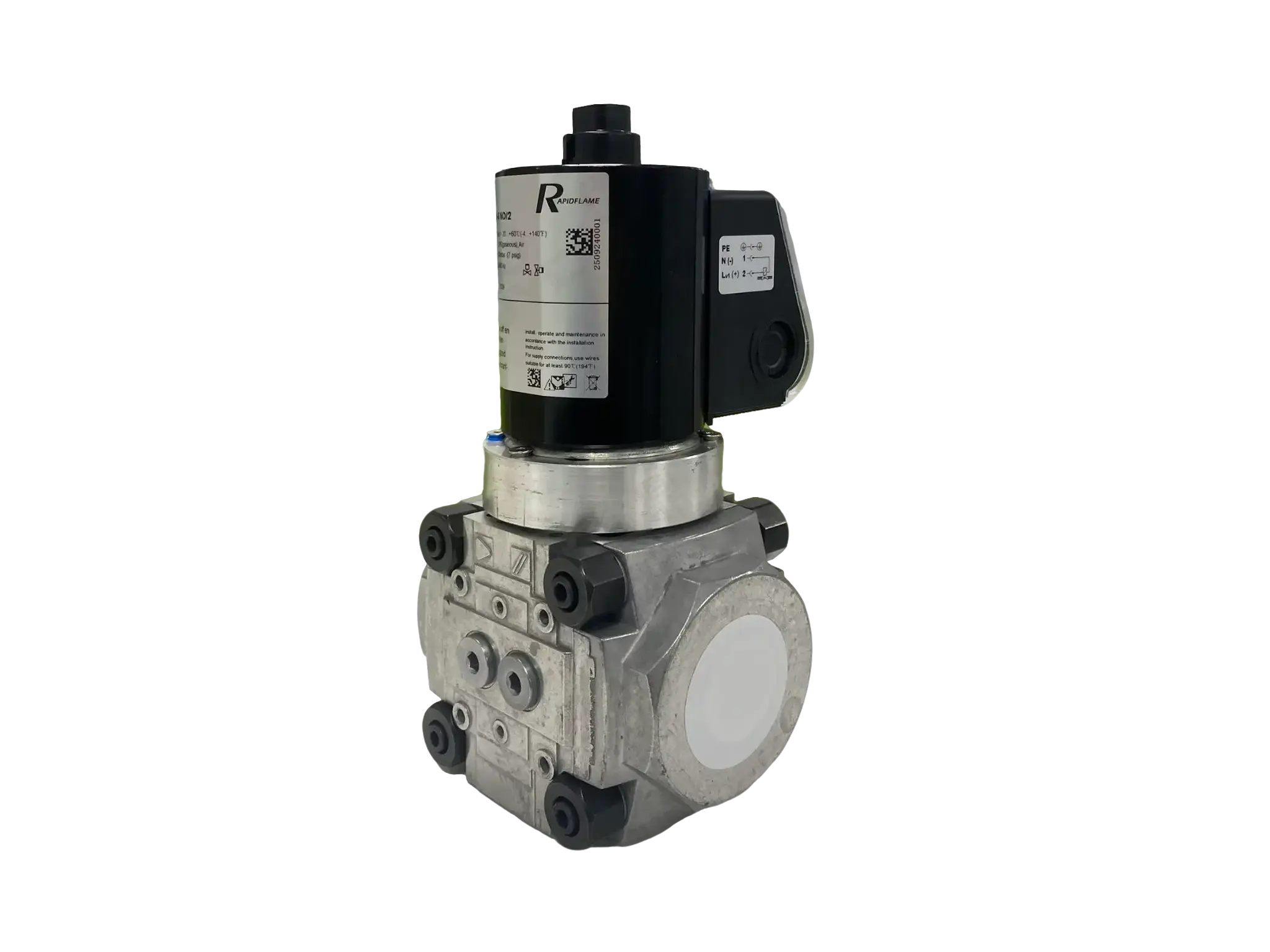
Main shutoff valves
Gas filters
Pressure regulators
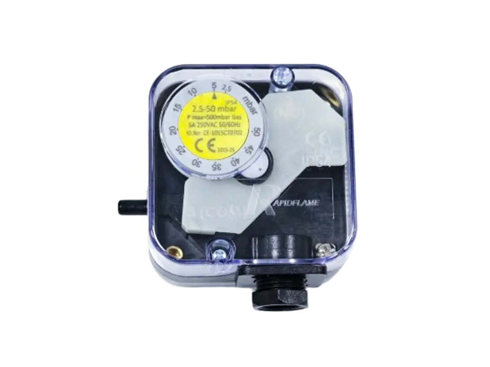
Pressure switches
Flow-control valves
Safety shutoff valves
Ignition-gas systems
Fuel-pressure monitoring
The OEM designer should provide the burner manufacturer with:
Fuel type
Fuel composition
Fuel pressure
Available flow
Minimum pressure
Maximum pressure
Expected pressure fluctuations
A burner should be evaluated across the actual operating range rather than only under nominal fuel conditions.
The combustion-air architecture depends on the burner type.
An OEM machine may use:
Dedicated combustion-air blower
Variable-speed blower
Central air supply
Pressure-controlled air
Process air
Natural entrainment
The burner and air system must be compatible in terms of:
Air volume
Air pressure
Air temperature
Control range
Pressure fluctuations
For a burner requiring a dedicated blower, the blower must provide sufficient pressure and flow across the entire firing range.
For an entrainment-type burner, the surrounding airflow and installation environment become particularly important.
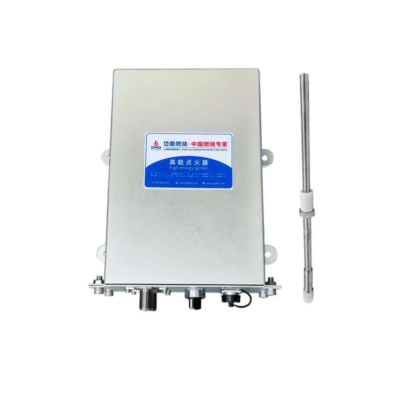
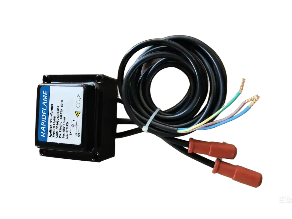
Reliable ignition is essential for an OEM combustion system.
A typical startup sequence may include:
Start Command
↓
Safety Check
↓
Air Preparation
↓
Fuel Valve Preparation
↓
Ignition
↓
Flame Detection
↓
Stable Flame Confirmation
↓
Normal Modulation
The system should detect whether the flame has actually been established.
If the flame is lost, the fuel supply must be handled according to the designed safety sequence.
The ignition and flame-detection system should therefore be considered part of the equipment architecture rather than an accessory added at the end.
Modern OEM equipment normally requires the burner to communicate with the machine's control system.
Typical signals may include:
Start
Stop
Heat demand
Reset
Enable
Ready
Running
Flame established
Fault
Flame failure
Gas-pressure fault
Air-pressure fault
Safety shutdown
The exact signal list depends on the equipment architecture.
The important principle is that responsibilities between the burner controller and the OEM PLC should be clearly defined.
Temperature control is one of the most important interfaces between the burner and the OEM machine.
A typical control loop is:
Temperature Setpoint
↓
Temperature Sensor
↓
PLC/PID Controller
↓
Burner Firing Rate
↓
Heat Release
↓
Equipment Temperature
The burner needs sufficient modulation capability to follow the required thermal load.
If the burner cannot operate stably at low load, the equipment may experience:
Temperature overshoot
Frequent burner cycling
Poor temperature stability
Increased component wear
Uneven product quality
Therefore, turndown ratio should be considered during burner selection.
The exhaust system directly affects combustion conditions.
Important parameters include:
Exhaust flow
Exhaust temperature
Furnace pressure
Chamber backpressure
Exhaust location
Exhaust-control method
An exhaust system that creates excessive backpressure can affect burner operation.
The relationship should therefore be evaluated as:
Burner → Combustion Chamber → Gas Flow → Exhaust
rather than designing each part independently.
Process airflow is especially important for drying and hot-air equipment.
In an indirect heating system, the burner may heat air that subsequently transfers energy to the product.
The system can therefore be represented as:
Burner → Heat Release → Air Heating → Process Air → Product
Important parameters include:
Airflow
Air velocity
Air temperature
Recirculation ratio
Mixing distance
Burner location
Exhaust location
A burner that produces excellent combustion performance may still produce poor equipment performance if the heated air is not distributed correctly.
Burner position should be determined from the equipment's thermal field.
The installation location affects:
Flame trajectory
Heat distribution
Product heating
Wall temperature
Gas circulation
Exhaust flow
The burner angle may also need to be optimized.
Possible arrangements include:
Horizontal firing
Upward firing
Downward firing
Opposed firing
Tangential firing
Multi-level firing
The correct arrangement depends on the equipment geometry and process requirements.
Before commissioning, verify the distance between the flame and all critical components.
Check for potential contact with:
Furnace walls
Refractory
Workpieces
Rollers
Supports
Shelves
Heat exchangers
Other burners
Flame clearance should be evaluated under different operating loads because flame shape can change as burner output changes.
A common mistake is to determine burner quantity simply by dividing total thermal demand by burner capacity.
For example:
1 MW thermal demand
does not automatically mean:
2 × 500 kW burners
The appropriate configuration depends on:
Furnace geometry
Heating zones
Temperature uniformity
Burner turndown
Flame interaction
Maintenance requirements
Control strategy
Multiple burners may provide better heat distribution, while a single larger burner may be more appropriate for another machine.
Burner maintenance should be considered before the equipment is manufactured.
Service personnel may need access to:
Ignition electrodes
Flame detectors
Burner heads
Valves
Filters
Pressure switches
Electrical connections
A good OEM design should allow critical components to be inspected and replaced without unnecessarily dismantling the machine.
This is particularly important for equipment intended for continuous industrial production.
High-temperature equipment undergoes thermal expansion during operation.
This can affect:
Burner mounting
Flanges
Refractory
Piping
Burner insertion depth
Electrical components
The mechanical interface should therefore account for the expected temperature range.
The burner should remain correctly positioned relative to the combustion chamber throughout startup, normal operation, and shutdown.
Burner safety should be integrated into the equipment's overall safety architecture.
Potential monitoring points include:
Fuel pressure
Combustion-air pressure
Flame status
Furnace pressure
Furnace temperature
Exhaust status
Door status
Emergency stop
High-temperature limit
A typical abnormal-condition response may be:
Flame Failure
↓
Fuel Shutoff
↓
Burner Fault
↓
Equipment Safe State
The exact sequence must be designed according to the burner system, equipment architecture, and applicable safety requirements.
A burner should not be considered fully integrated simply because it operates successfully during standalone testing.
The final test should evaluate the complete machine.
Important commissioning checks include:
Fuel pressure
Combustion-air pressure
Ignition
Flame stability
Minimum firing rate
Maximum firing rate
Temperature response
Furnace pressure
Exhaust performance
Safety interlocks
Alarm functions
Product heating uniformity
The actual OEM equipment may behave differently from a standalone burner test because chamber geometry, airflow, backpressure, and heat-transfer conditions are different.
A detailed technical package makes burner integration much easier.
Equipment type
Chamber dimensions
Operating temperature
Heating zones
Production capacity
Required heat load
Heating rate
Heat loss
Product temperature
Moisture load
Product type
Product dimensions
Product throughput
Product location
Required temperature uniformity
Fuel type
Fuel composition
Fuel pressure
Available flow
Pressure fluctuations
Combustion-air pressure
Airflow
Air temperature
Blower specifications
Exhaust flow
Exhaust temperature
Backpressure
Exhaust location
PLC platform
Temperature-control method
Required signals
Communication requirements
Burner opening
Mounting dimensions
Installation space
Insertion depth
Maintenance access
Drawings, CAD files, equipment photographs, and chamber cross-sections can be particularly useful during the engineering stage.
A customized burner becomes useful when a standard product cannot adequately match the equipment.
Typical reasons include:
Non-standard mounting dimensions
Limited installation space
Special flame requirements
Unusual furnace geometry
Special fuel
Unusual fuel pressure
High chamber backpressure
Special temperature distribution
Tight emission requirements
Special PLC interfaces
DYDTEC Combustion has 98%+ self-developed system products, providing greater flexibility when a project requires customized combustion-system configurations rather than a standard catalog solution.
There is no single answer.
This can be appropriate when the OEM already has combustion-system engineering capabilities and wants to integrate the burner into its existing architecture.
This can simplify fuel-system engineering while leaving the OEM responsible for the broader equipment controls.
This can be useful when the OEM wants the combustion supplier to handle:
Burner
Fuel system
Air system
Ignition
Flame detection
Safety components
Control interfaces
Commissioning
The appropriate scope depends on the OEM's engineering capabilities and project requirements.
Thermal capacity does not define flame characteristics.
Late mechanical changes can result in expensive equipment redesign.
The burner needs to operate under actual chamber conditions.
A burner may perform well at maximum output but poorly at minimum load.
The burner, fuel system, air system, exhaust, controls, and safety system are interconnected.
A difficult-to-access burner can increase equipment downtime.
Sometimes a customized combustion solution is more practical.
The final validation should take place on the complete OEM machine.
Burner suppliers can support OEM manufacturers at several levels.
Providing:
Industrial burners
Linear burners
Low-NOx burners
Specialized fuel burners
Ignition systems
Flame-detection systems
Providing:
Burner
Fuel train
Combustion-air system
Ignition
Flame detection
Safety components
Control interfaces
Supporting:
Thermal calculations
Burner selection
Flame analysis
Burner positioning
Control strategy
Customized interfaces
Supporting:
Prototype development
Customized burner design
Equipment testing
Commissioning
Performance optimization
For OEM manufacturers, early technical cooperation can significantly reduce the risk of redesigning the combustion system after the machine has already been built.
DYDTEC Combustion provides industrial combustion solutions covering burners, combustion systems, hot-air furnaces, and customized combustion equipment.
With production and R&D bases in Shanghai and Yangzhou, the company develops combustion solutions for different equipment configurations and industrial processes.
Its product portfolio includes 100+ burner models covering 200+ application scenarios, providing OEM manufacturers with multiple options for matching burner capacity, flame characteristics, fuel conditions, installation requirements, and process needs.
The scope can cover applications such as:
Industrial drying
Hot-air generation
Heat treatment
Preheating
Thermal oxidation
Industrial furnaces
Specialized heating equipment
Continuous-process equipment
The objective is to match the combustion system with the equipment rather than force the equipment to adapt to an unsuitable burner.
The earlier the burner is considered, the more design flexibility the OEM manufacturer has.
Early coordination allows engineers to optimize:
Burner Selection
↓
Combustion Chamber
↓
Burner Opening
↓
Fuel System
↓
Air System
↓
Exhaust System
↓
PLC & Safety
↓
Final Equipment
If the burner is selected only after the equipment has been completed, many important design decisions may already be fixed.
This can lead to:
Limited burner choices
Difficult installation
Poor flame positioning
Additional ducting
Control-system modifications
Higher redesign costs
For this reason, burner integration should ideally begin during the OEM equipment design stage.
Before finalizing the burner, confirm the following:
Required maximum heat input defined
Minimum heat load defined
Operating temperature defined
Heating rate defined
Temperature uniformity defined
Burner opening defined
Mounting flange defined
Flame clearance checked
Maintenance access provided
Thermal expansion considered
Fuel type confirmed
Fuel pressure confirmed
Fuel flow range confirmed
Fuel composition confirmed
Combustion-air source confirmed
Air pressure confirmed
Airflow confirmed
Air-control method defined
Exhaust location defined
Exhaust flow calculated
Chamber backpressure evaluated
PLC interface defined
Temperature-control method defined
Burner modulation defined
Alarm signals defined
Flame detection defined
Fuel shutoff logic defined
Emergency-stop logic defined
Pressure monitoring defined
High-temperature protection defined
Ignition tested
Flame stability tested
Minimum load tested
Maximum load tested
Temperature uniformity verified
Safety functions tested
Not necessarily. The burner must match the equipment's thermal load, geometry, fuel, air supply, exhaust conditions, control system, and safety architecture.
Ideally, yes. Early burner selection allows the mechanical and thermal design of the equipment to be optimized around the combustion system.
There is no single parameter. Thermal capacity, flame characteristics, turndown, fuel conditions, furnace geometry, installation requirements, and control requirements should be evaluated together.
The burner should be capable of meeting the required maximum heat load while also maintaining stable operation at the minimum required load.
A sufficient turndown ratio allows the burner to follow changing thermal demand without excessive cycling or temperature instability.
Yes, provided its operating range and flame characteristics are compatible with each machine. Installation configuration and operating parameters may need to be adjusted.
Yes. Chamber dimensions, burner location, product position, internal structures, and exhaust location all influence the appropriate flame characteristics.
The burner and PLC should have clearly defined command, status, alarm, and safety interfaces. The exact architecture depends on the equipment.
The combustion system requires appropriate safety functions, but the final architecture may be distributed between the burner controller, safety controller, and OEM PLC.
It depends on the project. Some OEMs purchase only the burner, while others prefer a complete combustion-system package.
Customization may be appropriate when standard burners cannot meet the required mounting dimensions, flame characteristics, fuel conditions, emissions, control interfaces, or process requirements.
The final test should be performed under actual equipment conditions, including thermal load, airflow, chamber pressure, exhaust conditions, temperature control, and safety functions.
Treating the burner as an isolated component. The burner must be designed together with the combustion chamber, fuel system, air system, exhaust, controls, and safety architecture.
Successful burner integration starts with the OEM equipment, not the burner catalog.
The burner must be matched to the complete operating environment:
Thermal Load
→ Furnace Geometry
→ Flame Characteristics
→ Fuel & Air
→ Exhaust
→ Temperature Control
→ PLC
→ Safety
→ Maintenance
The most effective approach is to involve the combustion-system supplier early, define the equipment's actual requirements, select the appropriate burner technology, design the mechanical and control interfaces, and validate the complete machine under real operating conditions.
For OEM manufacturers, the goal is not simply to make a burner ignite.
The goal is to make the burner function as a reliable, controllable, maintainable, and repeatable part of the entire machine.
That is the foundation of successful OEM burner integration.