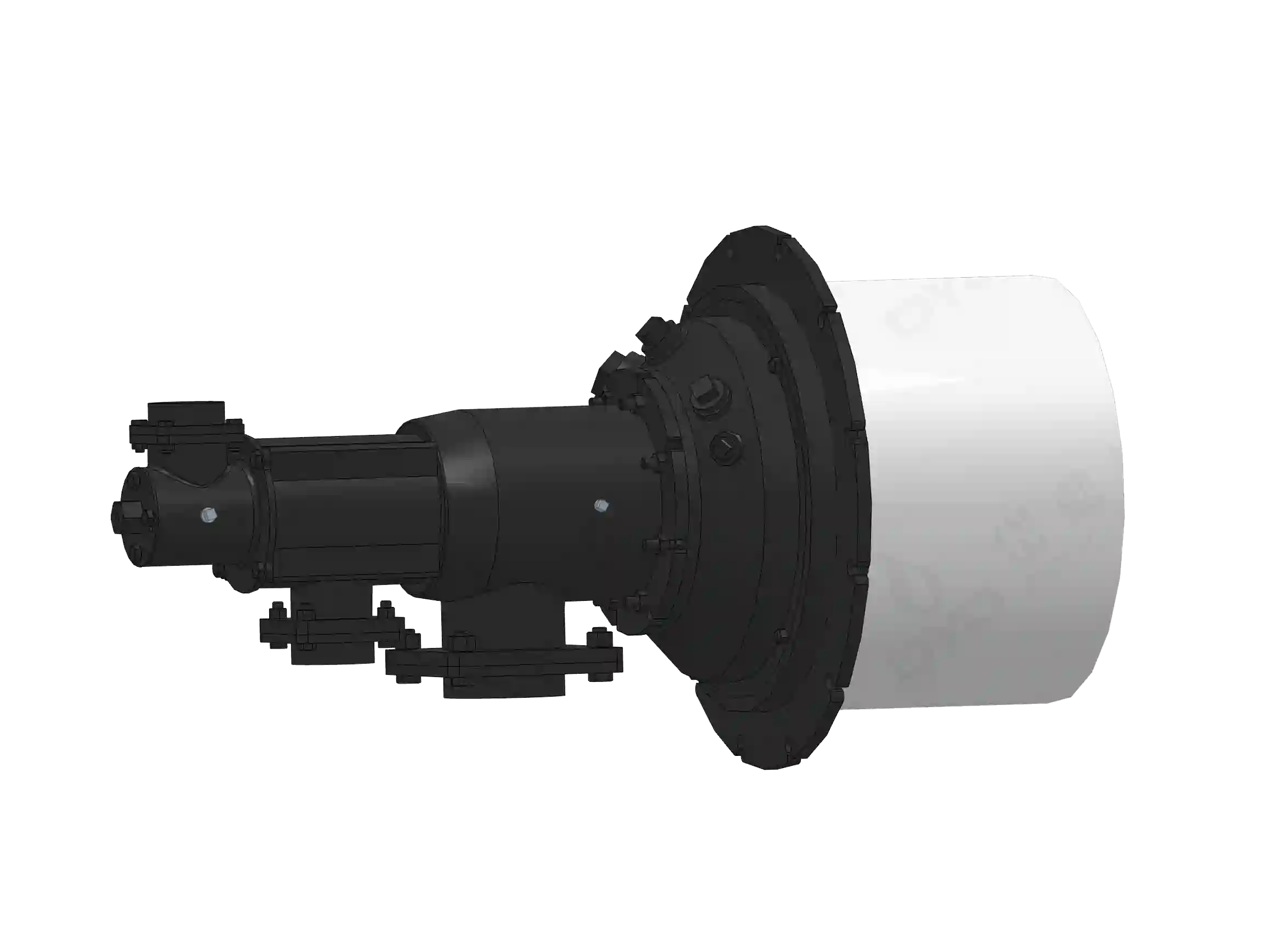
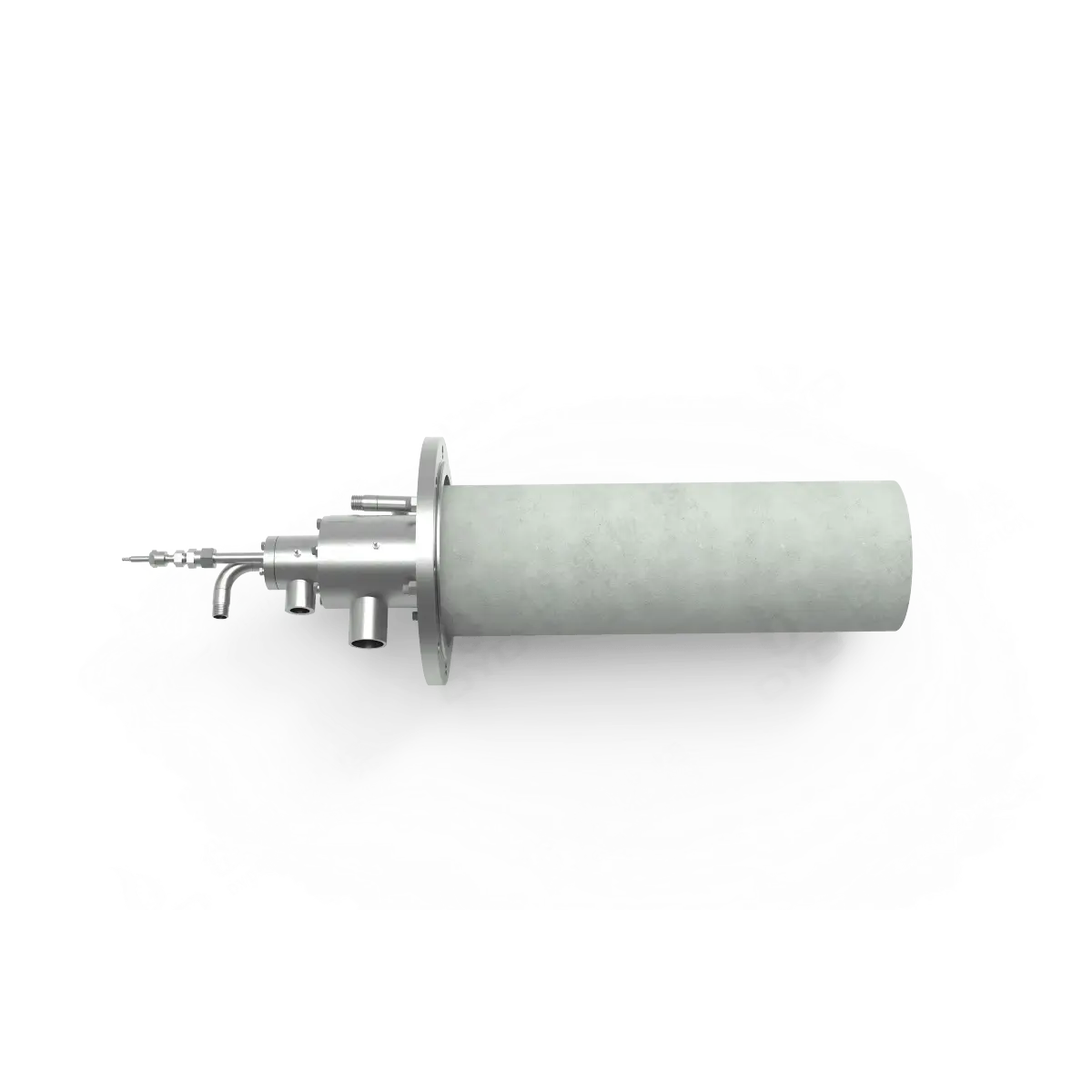
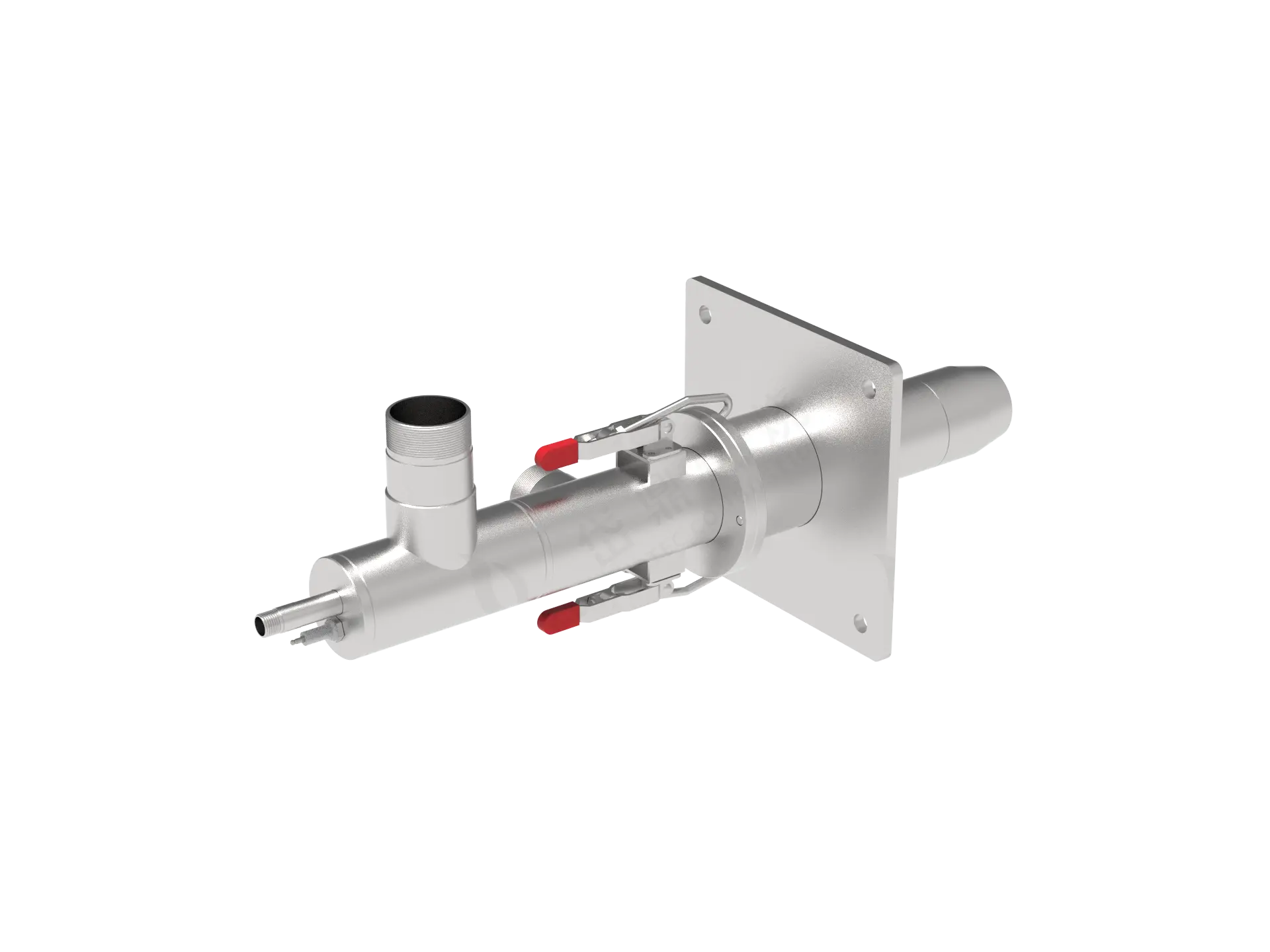
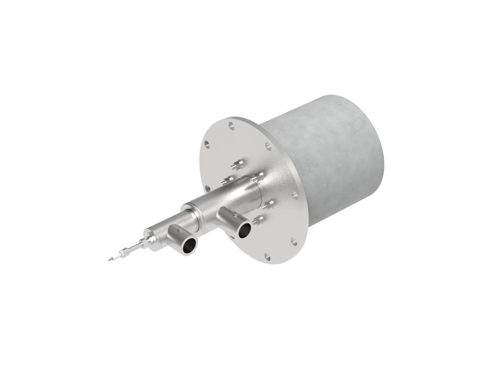
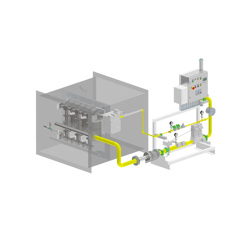
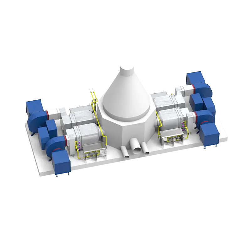
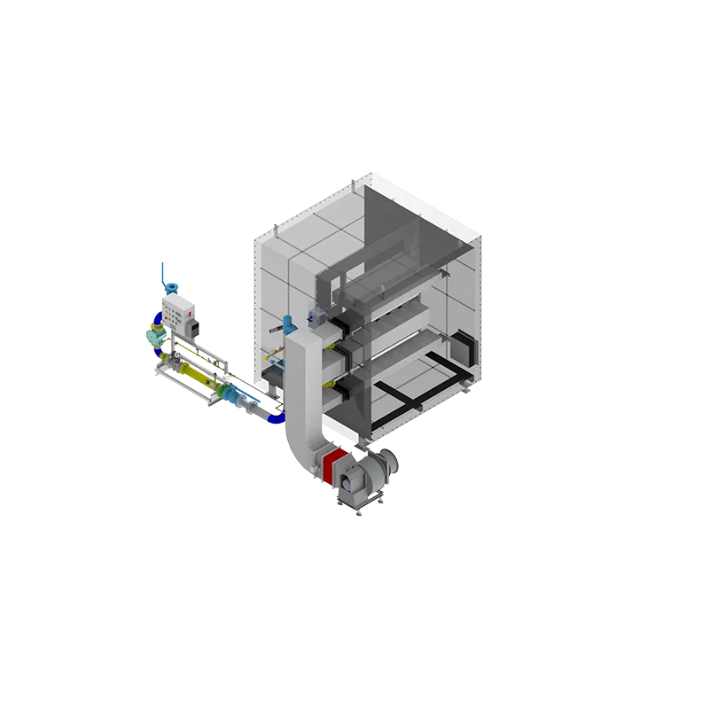
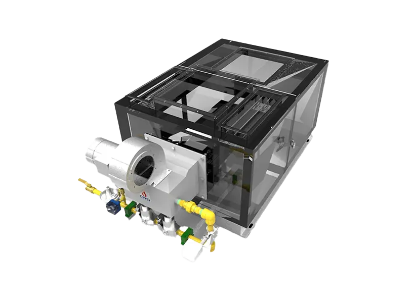
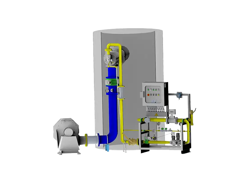
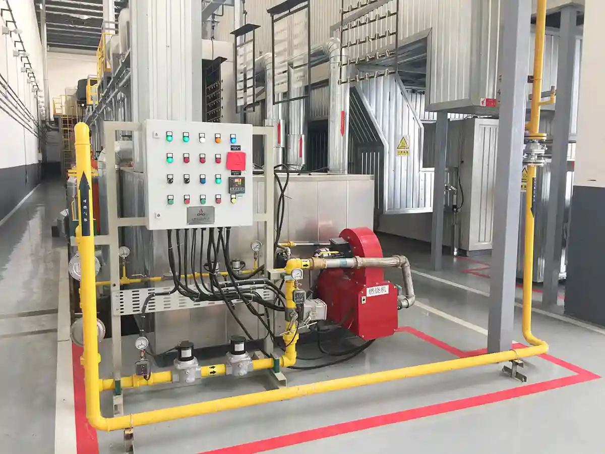
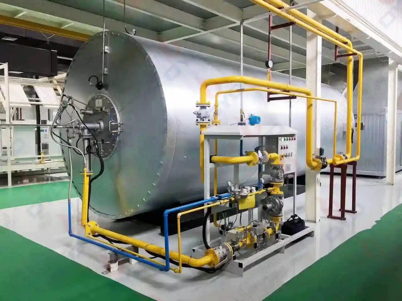
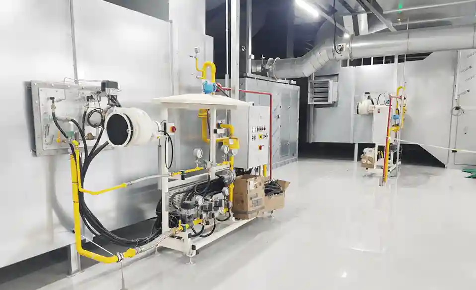
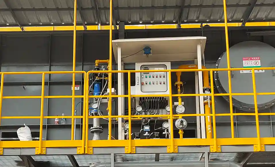
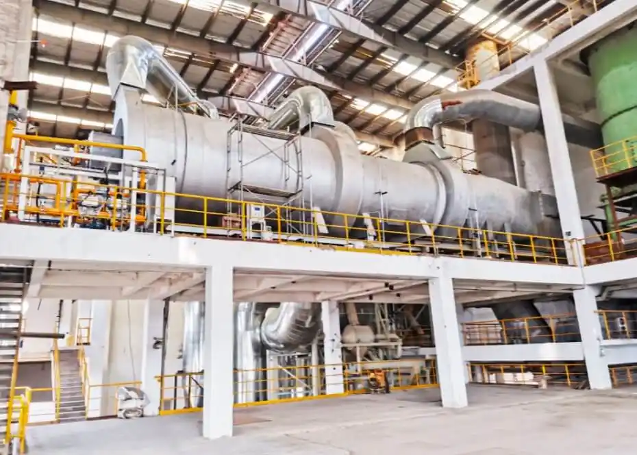
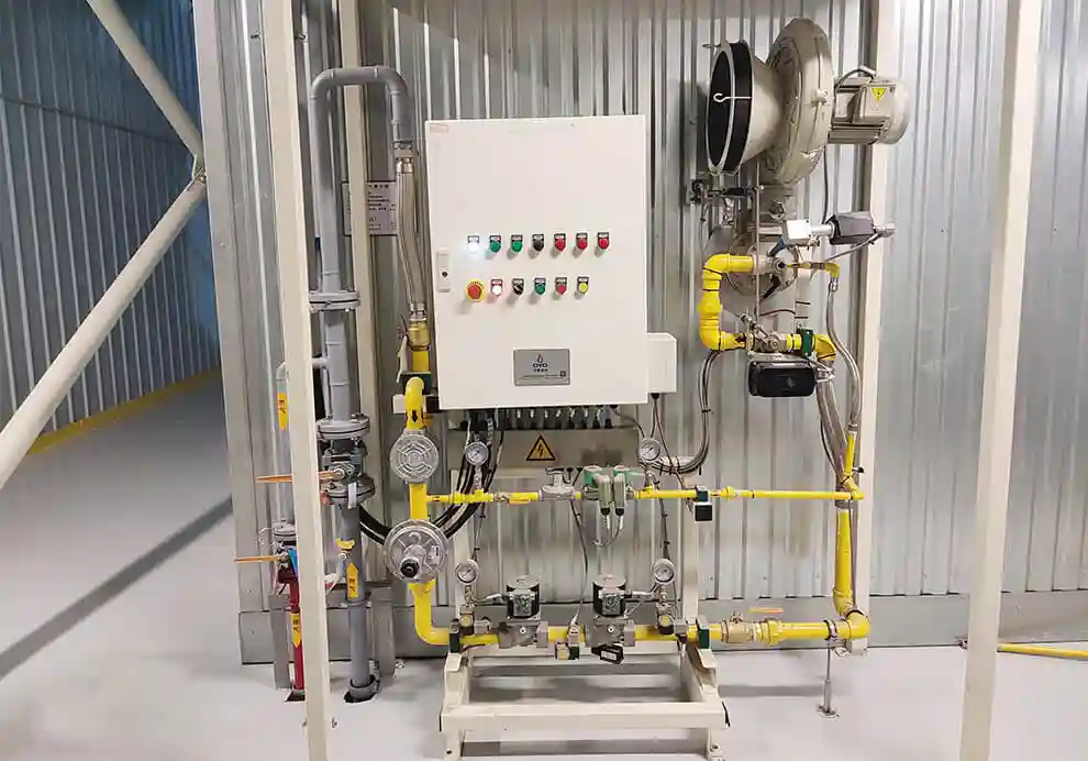
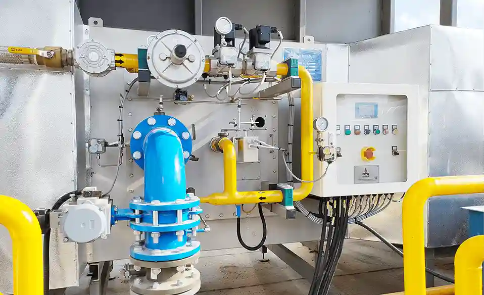
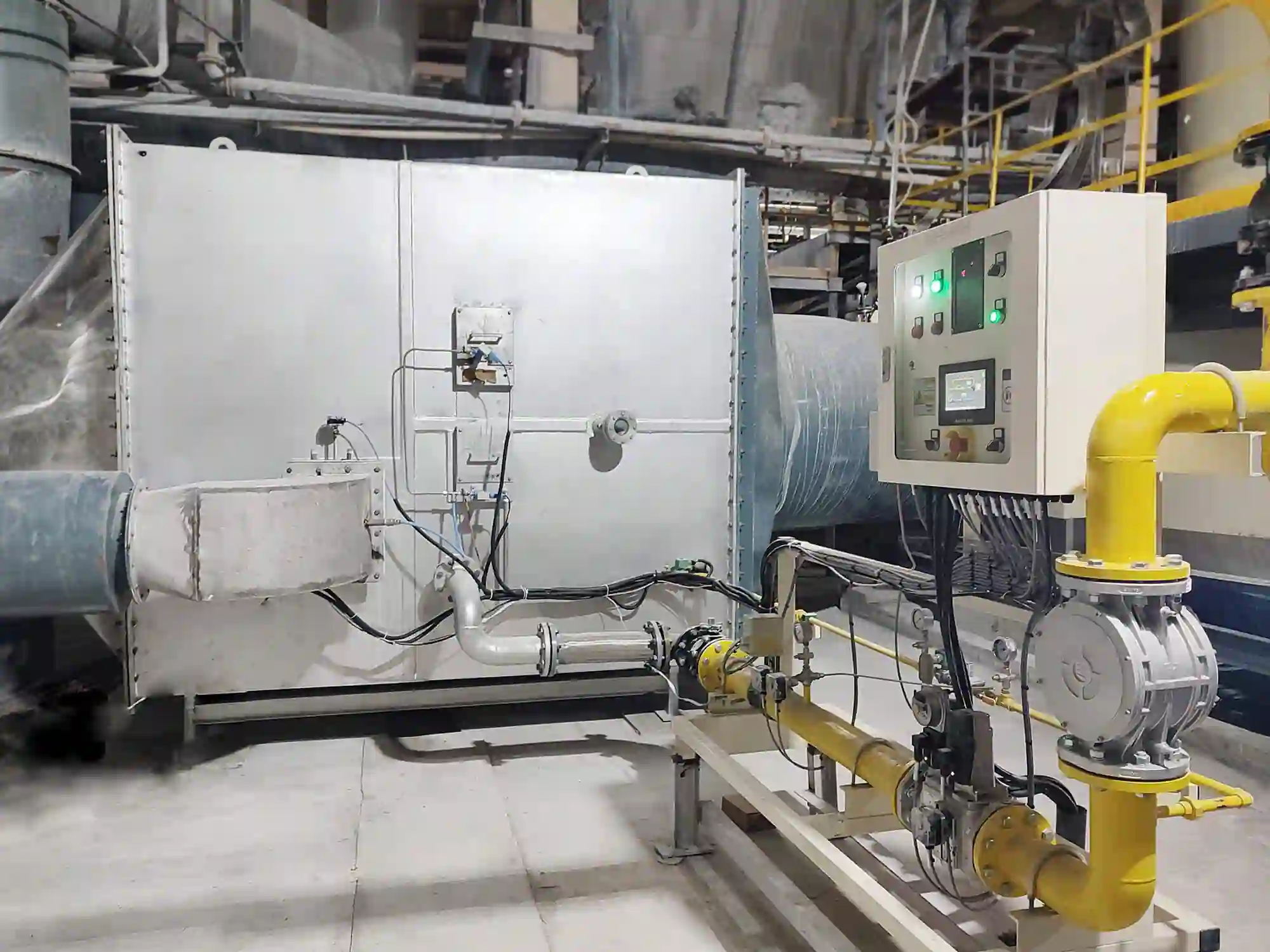
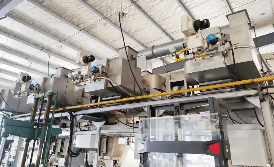
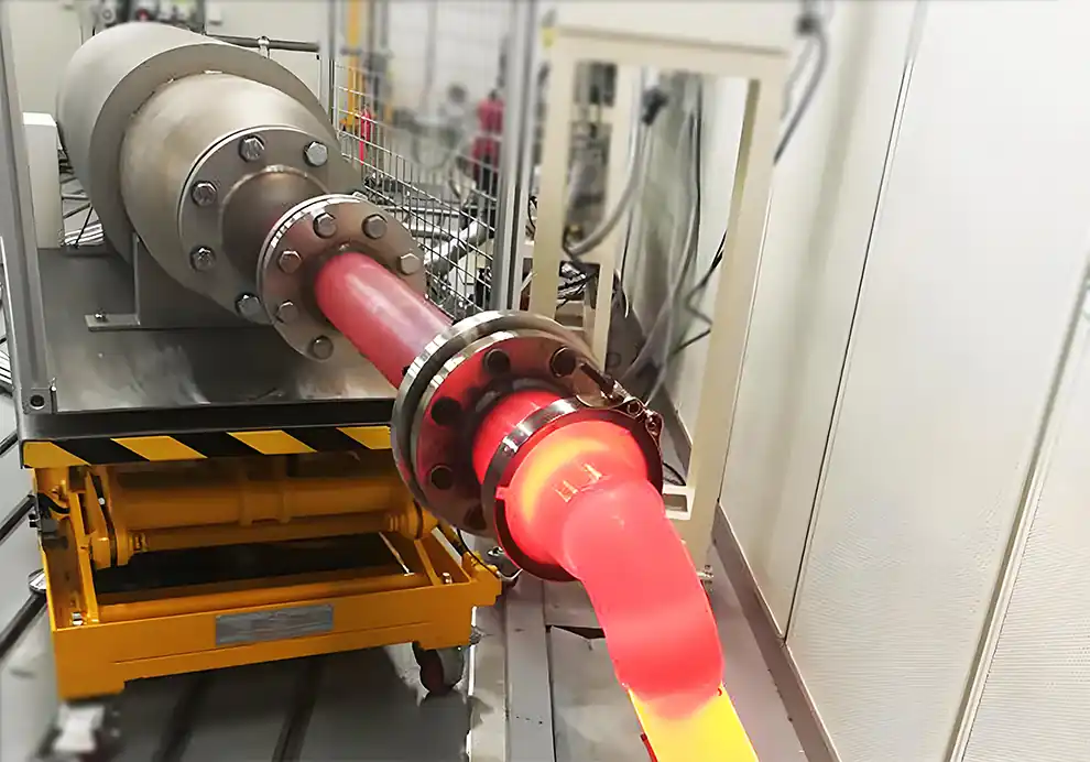
Industrial burners are often treated as individual components, but in OEM equipment they are actually part of a larger thermal system.
A burner that performs well in one furnace may not perform equally well when installed in another piece of equipment. Differences in furnace geometry, heat load, product position, airflow, exhaust, fuel conditions, temperature requirements, and control strategy can significantly affect burner performance.
Many burner-related problems in OEM equipment do not come from a fundamentally poor burner design. They come from a mismatch between the burner and the equipment.
Common consequences include:
Insufficient heating capacity
Excessive fuel consumption
Uneven temperature distribution
Flame instability
Flame impingement
Local overheating
Poor low-load operation
Excessive exhaust temperature
Difficult commissioning
Inconsistent product quality
The key principle is:
A burner should be designed and selected as part of the OEM equipment, not as an isolated component.
A burner design mistake occurs when the combustion system is not adequately matched to the actual operating requirements of the equipment.
This can happen during:
Furnace design
Burner selection
Mechanical integration
Fuel-system design
Combustion-air design
Control-system design
Commissioning
Some mistakes are obvious, such as selecting a burner with insufficient capacity.
Others are less obvious, such as selecting the correct capacity but using the wrong flame length, burner angle, or installation position.
OEM equipment is often designed around a specific production process.
The burner must fit within constraints such as:
Limited installation space
Fixed furnace dimensions
Existing fuel connections
Specific product positioning
Required heating rate
Required temperature uniformity
Production throughput
Exhaust limitations
A standard burner may meet the nominal thermal requirement but still be unsuitable for the complete machine.
This is why burner selection should begin with the equipment and process rather than starting with a burner model.
One of the most common mistakes is selecting a burner simply because its maximum capacity appears to be large enough.
For example, an OEM may calculate that the furnace requires approximately 800 kW and immediately select a burner rated at 1,000 kW.
But maximum capacity is only one parameter.
The burner also needs to operate effectively at:
Normal operating load
Minimum load
Startup load
Production fluctuations
If the furnace normally requires only 200–400 kW, a burner with an excessively high minimum output may have difficulty maintaining stable temperature control.
Therefore:
Burner capacity should be matched to the complete operating range, not just the maximum heat load.
Maximum capacity gets most of the attention during burner selection, but minimum controllable output can be equally important.
Consider a furnace that operates between:
150 kW and 800 kW
The burner needs to provide enough capacity for the upper end while remaining stable at the lower end.
If the burner cannot reduce its output sufficiently, the system may experience:
Temperature overshoot
Frequent burner cycling
Poor temperature stability
Local overheating
Inefficient low-load operation
This is why turndown ratio should be evaluated as part of the burner selection process.
A burner does not operate in empty space.
Its flame develops inside a specific chamber with specific:
Length
Width
Height
Volume
Wall structure
Internal components
Product location
A burner with a long flame may work well in a long furnace but become problematic in a compact chamber.
A high-momentum flame may be appropriate for one application but unsuitable for another.
Therefore:
Furnace geometry is a fundamental burner-selection parameter.
Flame length is particularly important in OEM equipment.
If the flame is too long, it may:
Hit the furnace wall
Contact the product
Create local overheating
Increase refractory temperature
Change combustion behavior
If the flame is too short, heat release may become concentrated near the burner.
This can create:
Hot zones
Poor heat distribution
Underheated areas farther from the burner
The ideal flame length should be compatible with the chamber dimensions and product location.
Two burners with similar thermal capacity can produce very different flame shapes.
Important characteristics include:
Flame length
Flame width
Flame momentum
Flame temperature
Mixing characteristics
A narrow flame may concentrate heat in a small area.
A wider flame may distribute thermal energy across a larger region.
The correct flame shape depends on the application.
Therefore, burner selection should consider how the heat is released, not just how much heat is released.
Burner installation location has a direct influence on heat distribution.
Common installation positions include:
Side wall
End wall
Roof
Floor
Multiple locations
The wrong position can cause:
Uneven temperature
Flame impingement
Poor circulation
Excessive wall heating
Short-circuiting of hot gases toward the exhaust
The burner should be positioned according to the intended thermal flow through the furnace.
Burner angle determines the direction of the flame and initial hot-gas movement.
A poorly selected angle can send the flame:
Directly toward the product
Directly toward a furnace wall
Straight toward the exhaust
Into an area where heat transfer is not useful
An appropriate angle can instead encourage better gas circulation and more effective heat transfer.
For OEM equipment, burner angle should therefore be considered during mechanical design rather than left entirely to installation technicians.
Direct flame exposure can create localized heating.
Depending on the product, this may cause:
Surface overheating
Uneven treatment
Material deformation
Oxidation
Localized thermal damage
A furnace may have the correct average temperature while the product surface experiences a much higher local heat flux.
The burner-to-product distance should therefore be evaluated together with flame characteristics and product sensitivity.
If the burner and exhaust are positioned too close together, hot combustion gases may travel directly from the flame to the exhaust.
The result can be:
Burner → Hot Gas → Exhaust
with insufficient heat transfer to the product.
This can increase exhaust heat loss and reduce thermal utilization.
The desired flow path is closer to:
Burner → Hot Gas → Product → Heat Transfer → Exhaust
The actual arrangement depends on furnace geometry and process requirements.
Burner performance cannot be separated from the exhaust system.
The exhaust system affects:
Furnace pressure
Gas velocity
Combustion-gas residence time
Heat distribution
Cold-air infiltration
An oversized exhaust system may create excessive negative pressure.
An undersized exhaust system may restrict gas removal.
Both conditions can influence combustion and temperature control.
Therefore:
Burner capacity and exhaust capacity should be evaluated together.
Furnace pressure affects combustion stability and gas movement.
Depending on the equipment, the furnace may operate at:
Slight negative pressure
Near-atmospheric pressure
Slight positive pressure
If furnace pressure is not properly considered, the system may experience:
Cold-air infiltration
Flame instability
Excessive exhaust
Temperature fluctuations
Combustion-control difficulties
The burner, furnace, and exhaust system should therefore be designed as a pressure-balanced system.
A burner requires combustion air under specific conditions.
Important parameters include:
Air pressure
Air temperature
Air volume
Air quality
Air-control method
If the actual air supply differs significantly from the conditions assumed during burner selection, flame behavior can change.
Possible effects include:
Flame instability
Changes in flame length
Changes in heat release
Incomplete combustion
Increased excess air
Combustion-air conditions should therefore be defined before final burner selection.
More air does not automatically mean better combustion.
Excessive air can increase the amount of gas that must be heated and eventually discharged through the exhaust.
This can increase:
Exhaust gas volume
Exhaust heat loss
Fuel consumption
However, reducing air excessively is also problematic because it can lead to incomplete combustion and increased CO.
The objective is to maintain an appropriate air-to-fuel relationship for the burner and process.
Fuel pressure is another critical parameter.
The burner needs to operate within its intended fuel-pressure range.
If actual fuel pressure is too low, the burner may not achieve its intended capacity.
If pressure is significantly different from the design condition, flame characteristics can also change.
Therefore, OEM equipment should define:
Fuel type
Fuel pressure
Pressure fluctuation
Fuel flow requirements
before the burner is finalized.
Another common mistake is choosing the burner first and calculating heat demand later.
A proper design process should generally work in the opposite direction:
Process Requirements
↓
Heat-Load Calculation
↓
Operating Range
↓
Burner Capacity
↓
Burner Characteristics
↓
Burner Arrangement
↓
Control System
The thermal requirement should be established before final burner selection.
Furnace volume does not directly determine heat load.
Actual thermal demand depends on factors such as:
Product throughput
Product temperature
Specific heat
Moisture content
Heating rate
Furnace heat loss
Exhaust heat loss
Process requirements
Two furnaces with similar volumes can have very different burner requirements.
Therefore:
Furnace volume is an input to furnace design, not a substitute for heat-load calculation.
For continuous industrial equipment, production throughput can have a major influence on heat load.
Increasing the amount of material processed per hour generally increases the useful heat required.
For example:
Higher Throughput → More Material Heating → Higher Thermal Demand
A burner selected for one production capacity may become insufficient if the OEM later increases machine throughput.
Production capacity should therefore be included in the original thermal calculation.
For drying equipment, moisture can represent a major part of the total heat load.
The combustion system may need to provide energy for:
Heating the material
Heating the water
Evaporating the water
Heating process air
Compensating for exhaust losses
Ignoring moisture can lead to significant underestimation of burner capacity.
This is especially important for:
Grain drying
Chemical powder drying
Battery-material drying
Food processing
Industrial coating processes
Startup conditions can require much more thermal energy than steady-state operation.
During startup, the system may need to heat:
Furnace walls
Refractory
Internal structures
Product
Process air
If burner capacity is selected only according to the steady-state holding load, startup may take too long.
Therefore, OEMs should distinguish between:
Startup Heat Load
and
Steady-State Heat Load
Standardization can be valuable for OEM manufacturers, but the same burner configuration should not automatically be applied to every furnace.
Different equipment may have different:
Furnace dimensions
Heat loads
Product positions
Temperature requirements
Exhaust arrangements
A burner configuration that works well on one machine may not provide the same performance on another.
Standardization should therefore be balanced with process-specific engineering.
More burners do not automatically mean better temperature uniformity or higher efficiency.
An excessive number of burners can create:
Complex piping
Difficult control
Flame interaction
Higher maintenance requirements
More complicated commissioning
The objective should be to use an appropriate number of burners to provide the required heat distribution and control.
The opposite mistake can also occur.
Using too few burners can result in:
Concentrated heat input
Poor temperature distribution
Large temperature gradients
Difficulty controlling different zones
For long or large furnaces, distributed burner arrangements may provide better thermal control.
In multi-burner systems, spacing matters.
If burners are too close:
Flames may interact excessively
Local heat release may become concentrated
If burners are too far apart:
Cold zones may appear
Heat distribution may become uneven
Burner spacing should therefore be determined according to:
Flame characteristics
Furnace dimensions
Heat-load distribution
Product position
Multiple burners do not operate independently.
Their flames and combustion gases interact.
Poorly designed arrangements can result in:
Flame interference
Uneven gas flow
Local overheating
Unstable temperature distribution
A properly engineered arrangement can instead use the interaction between burners to promote controlled circulation.
The difference is whether the interaction is designed or accidental.
A burner can deliver the required thermal capacity and still produce poor temperature uniformity.
For example, a furnace may require:
800 kW
A burner provides exactly 800 kW.
But if most of that heat is concentrated near one area, the furnace may still have cold zones elsewhere.
Therefore, burner design should consider:
Where heat is released
How gases circulate
Where the product is located
Where the exhaust is located
The question is not only:
How much heat?
but also:
Where does the heat go?
Different products have different thermal tolerances.
Some products can tolerate direct exposure to hot gases.
Others are highly sensitive to:
Local temperature
Flame radiation
Heating rate
Temperature gradients
Burner selection should therefore consider the product itself.
A burner arrangement suitable for a refractory product may not be suitable for a temperature-sensitive material.
Many OEM machines do not operate at full capacity continuously.
They may run at:
Full production
Reduced production
Startup
Shutdown
Holding conditions
If the burner system is designed only around maximum load, it may perform poorly during the rest of the operating cycle.
Part-load performance should therefore be considered from the beginning.
The burner and control system should be designed together.
Important control functions may include:
Ignition
Flame detection
Fuel modulation
Air modulation
Temperature control
Burner staging
Safety interlocks
If the burner is capable of precise modulation but the control system cannot use it effectively, the potential performance of the burner may not be realized.
A burner system is not complete without appropriate flame supervision and safety control.
Important functions may include:
Ignition sequence
Flame detection
Fuel shutoff
Purging
Interlocks
Fault handling
These systems should be considered during OEM equipment development rather than added at the final commissioning stage.
A robust OEM combustion system should consider more than normal operating conditions.
Engineers should evaluate:
Startup
Shutdown
Maximum load
Minimum load
Fuel-pressure variation
Air-pressure variation
Door opening
Production changes
Abnormal conditions
A system that works perfectly at one operating point may not remain stable across the complete operating range.
A systematic design process can significantly reduce the risk of mismatch.
Determine:
What is being heated?
What temperature is required?
How quickly must it be heated?
How much material is processed?
Consider:
Product heating
Moisture evaporation
Furnace heat loss
Exhaust heat loss
Startup requirements
Identify:
Maximum load
Normal load
Minimum load
Startup load
Determine:
Burner locations
Product positions
Flame-development space
Exhaust location
Internal structures
Evaluate:
Capacity
Turndown
Flame length
Flame shape
Momentum
Fuel requirements
Determine:
Number of burners
Spacing
Angle
Heating zones
Burner-to-product distance
Match:
Combustion air
Fuel flow
Exhaust flow
Furnace pressure
Integrate:
Ignition
Flame detection
Modulation
Staging
Temperature control
Safety interlocks
Evaluate:
Temperature uniformity
Fuel consumption
Flame stability
Product quality
Startup performance
Part-load performance
DYDTEC Combustion develops industrial burners and combustion-system solutions for different industrial heating applications.
Its product portfolio includes 100+ burner models and covers 200+ application scenarios, allowing burner configurations to be considered according to different furnace structures, heat loads, fuels, and process requirements.
For OEM equipment, the combustion system can be evaluated around:
Furnace geometry
Heat load
Burner capacity
Flame characteristics
Burner position
Burner angle
Airflow
Exhaust
Temperature uniformity
Control requirements
DYDTEC Combustion was established in 2012, with R&D and manufacturing bases in Shanghai and Yangzhou and a factory area of approximately 11,000 m².
Its 98%+ self-developed system product rate supports applications where the combustion system needs to be integrated with specific OEM equipment rather than selected solely as an off-the-shelf component.
One of the most expensive mistakes is waiting until the furnace has already been designed before considering the burner.
By that stage, the equipment may already have fixed:
Burner openings
Furnace dimensions
Exhaust position
Fuel connections
Air connections
Product position
Changing the burner afterward can require significant modifications.
Early combustion-system involvement allows the OEM to coordinate:
Furnace Geometry + Burner + Air + Fuel + Exhaust + Control
from the beginning.
This can reduce integration problems during commissioning.
A useful technical package should include:
Internal dimensions
Wall construction
Insulation
Burner installation location
Exhaust location
Required temperature
Heating rate
Holding time
Production capacity
Operating cycle
Material
Mass
Dimensions
Position
Moisture content where applicable
Fuel type
Fuel pressure
Combustion-air pressure
Required heat load
Modulation requirements
Number of heating zones
Temperature sensors
Safety requirements
The more complete the information, the easier it is to determine whether a standard burner or a customized combustion-system configuration is appropriate.
One of the most common mistakes is selecting a burner based only on maximum heat capacity without considering the furnace geometry, operating range, flame characteristics, and heat-distribution requirements.
Yes. If the burner cannot operate effectively at the furnace's normal low-load condition, it may cause cycling, temperature overshoot, and inefficient operation.
Neither should be considered independently. Capacity determines how much heat can be supplied, while flame characteristics influence where and how that heat is released.
Yes. Burner position affects gas circulation, heat transfer, wall heating, product exposure, and exhaust losses.
Burner angle determines the direction of flame and hot-gas movement and can significantly influence heat distribution.
Sometimes, but not always. The correct configuration depends on furnace geometry, heat-load distribution, temperature requirements, and control needs.
The flame must develop within the available chamber space. Furnace dimensions and internal structures influence flame behavior and hot-gas circulation.
It determines how effectively the burner can operate across the furnace's actual thermal-load range.
Yes. Excessive air increases the amount of gas that must be heated and may increase exhaust heat loss.
Yes. Exhaust flow influences furnace pressure, gas circulation, heat transfer, and combustion stability.
Ideally, burner requirements should be considered during furnace design so that burner, furnace geometry, airflow, and exhaust can be coordinated.
Because product mass, throughput, temperature requirements, moisture, and position directly affect heat load and burner configuration.
Yes, when its capacity, flame characteristics, installation conditions, and operating range match the equipment. More specialized equipment may require customized configuration.
Provide complete process and equipment information early, design the burner and furnace as an integrated system, and test the system under realistic operating conditions.
The most common burner design mistakes in OEM equipment are rarely limited to the burner itself.
They often result from a mismatch between:
Burner
Furnace
Heat Load
Air
Fuel
Exhaust
Control
and Product Requirements.
The most important design principles are therefore:
Do not select a burner based only on maximum capacity.
Consider minimum controllable output.
Match flame characteristics to furnace geometry.
Optimize burner position and angle.
Design burner arrangement around heat distribution.
Coordinate combustion air with fuel.
Consider exhaust and furnace pressure.
Design for startup and part-load conditions.
Integrate burner control and safety systems early.
Test the complete system under realistic production conditions.
For OEM manufacturers, the burner should be regarded as a core thermal component of the equipment, rather than simply a purchased accessory.
The right approach is to start with the process, calculate the actual heat demand, understand the furnace geometry, and then design the combustion system around those requirements.
Ultimately:
A successful OEM burner design is not simply a burner that can produce enough heat. It is a combustion system that can deliver the right heat, in the right place, at the right rate, under the actual operating conditions of the equipment.