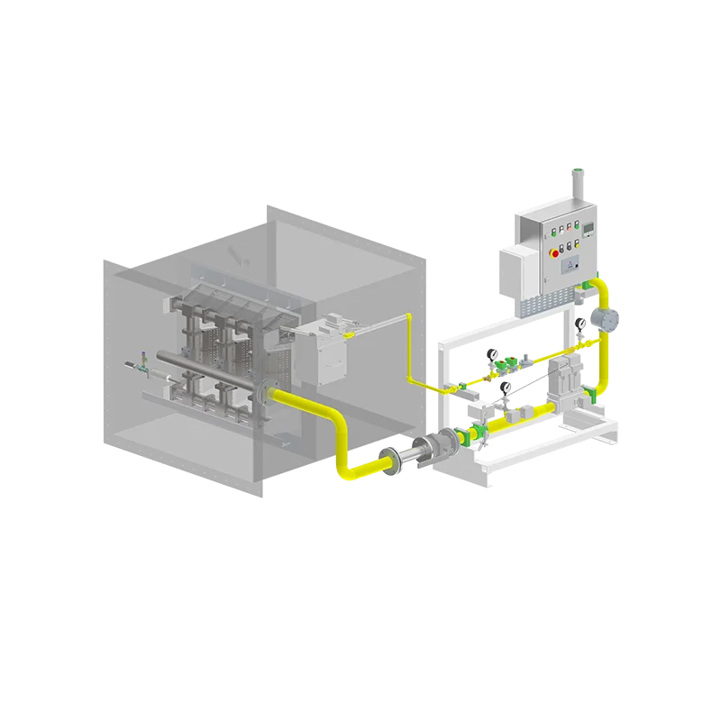
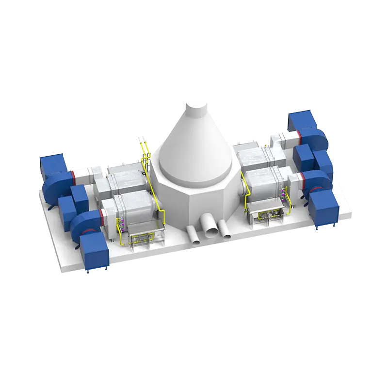
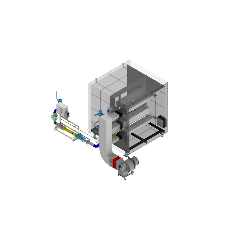
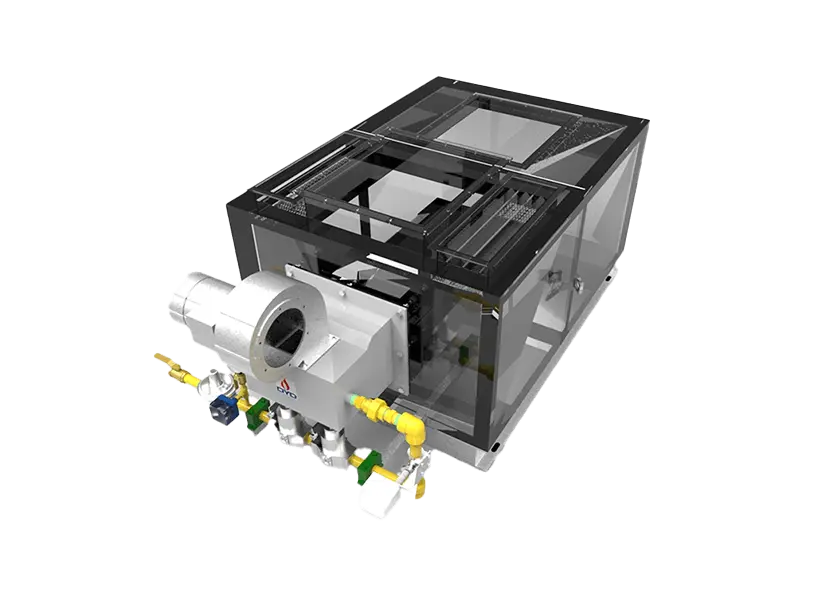
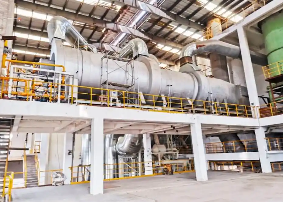
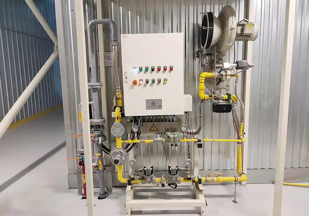
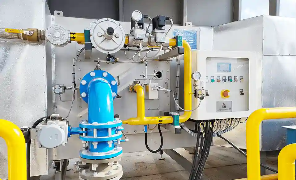
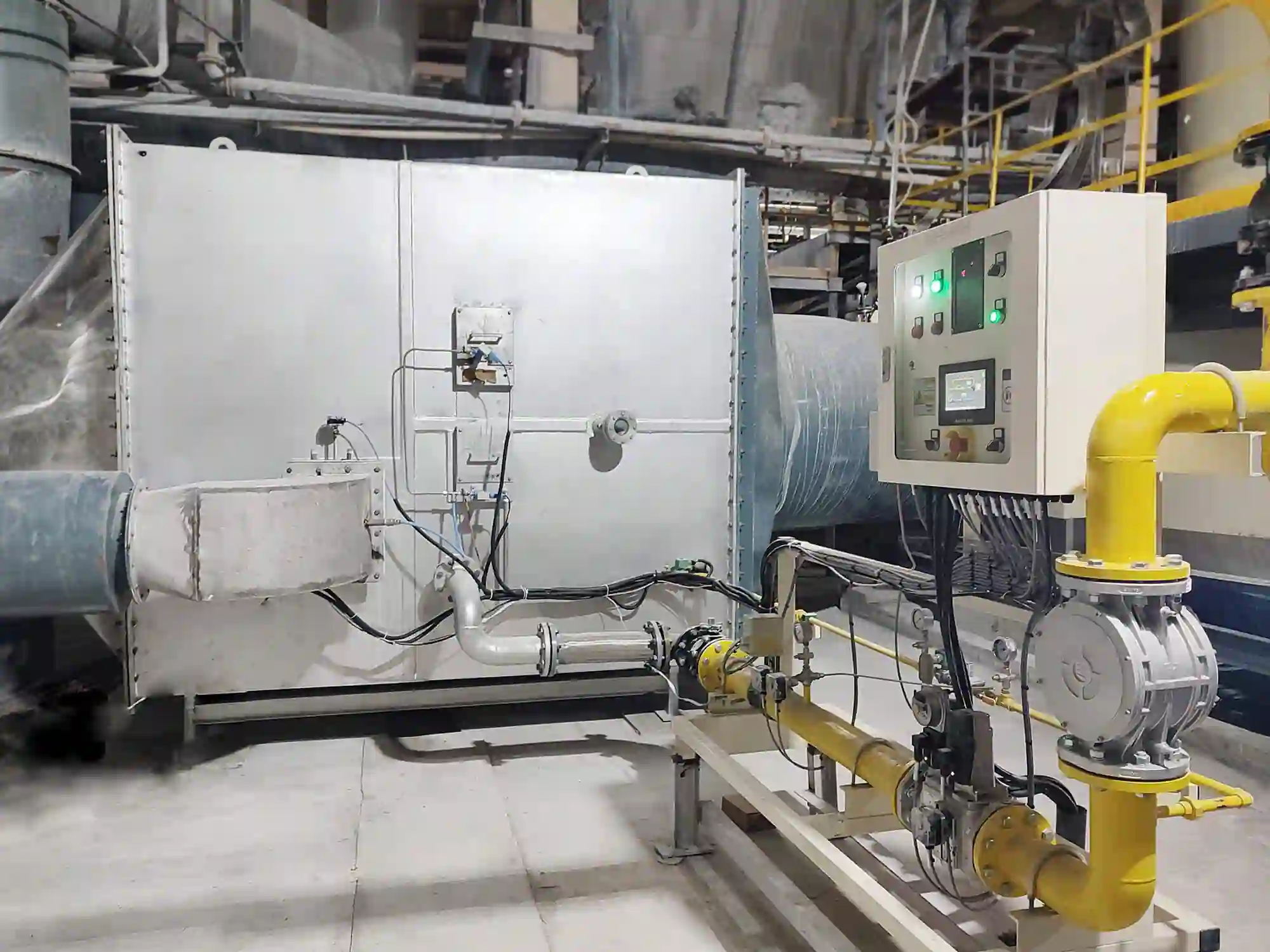
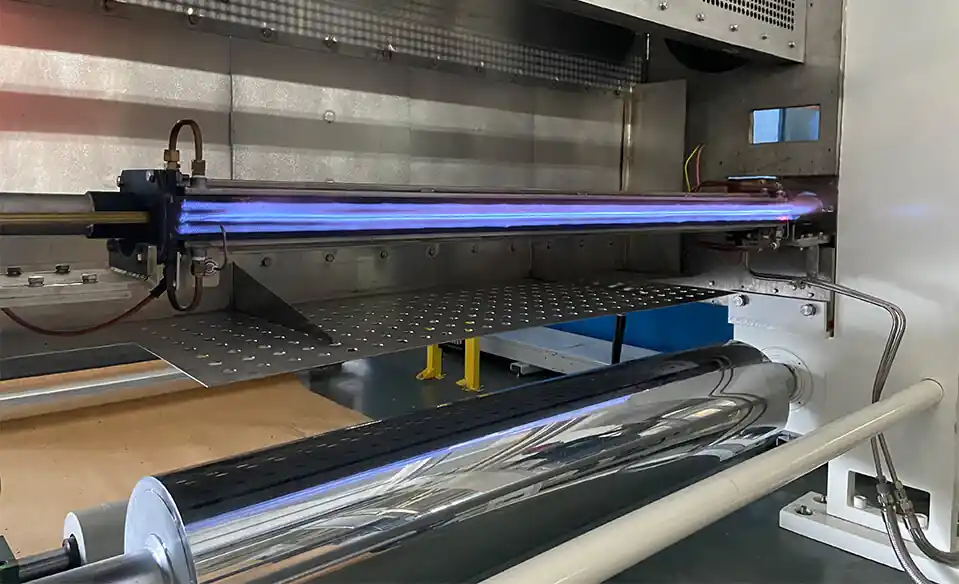
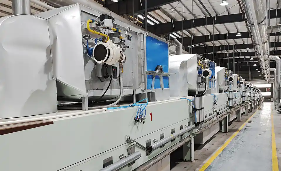
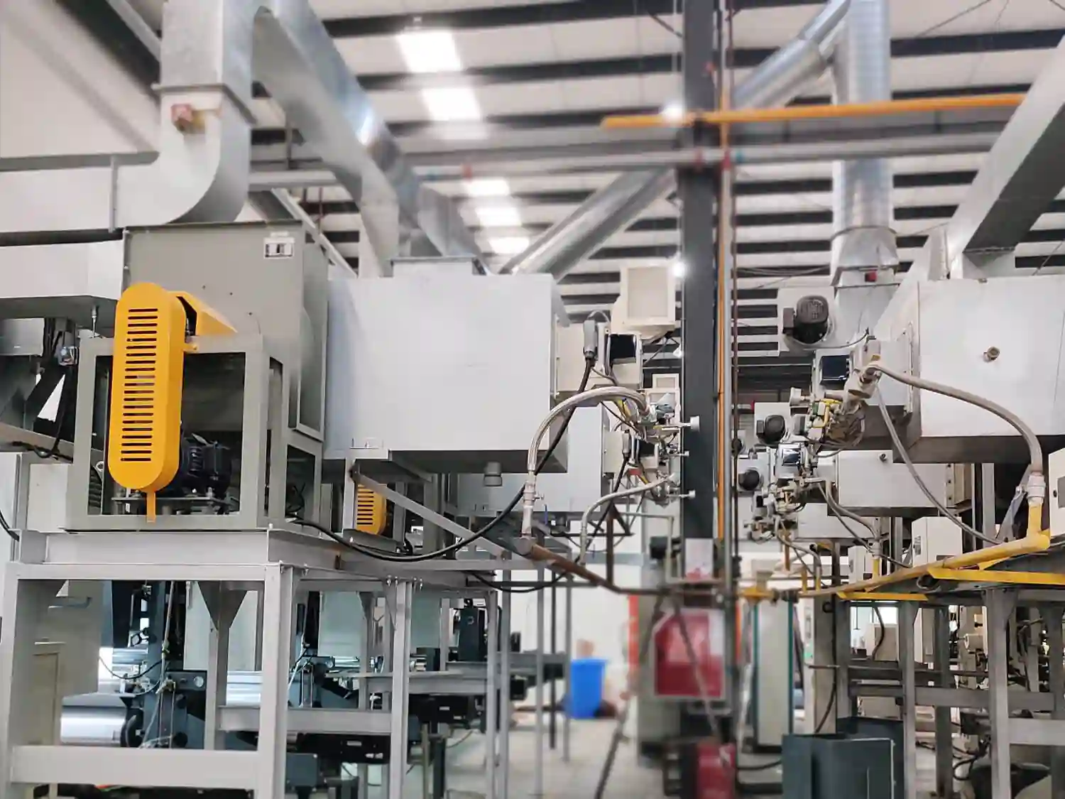
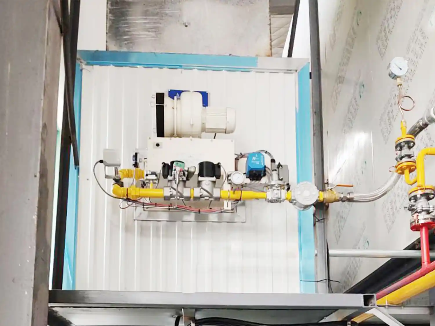
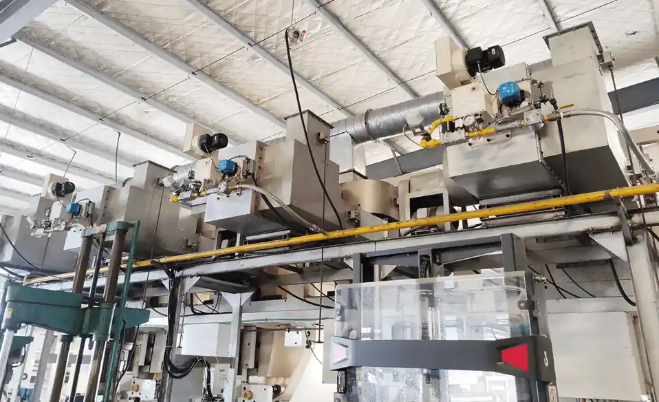
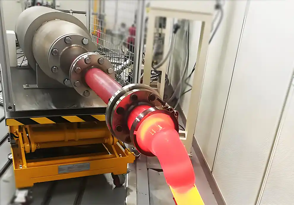
Burner arrangement has a direct influence on the thermal efficiency, temperature uniformity, combustion stability, and controllability of an industrial furnace.
A burner does not operate in isolation. Its position relative to other burners, the furnace walls, the product, and the exhaust determines how combustion heat is distributed and how effectively that heat is transferred to the process.
Two furnaces can use burners with the same rated capacity and fuel, yet achieve different fuel consumption and thermal performance because their burner arrangements are different.
The key principle is:
Burner efficiency is not determined only by the burner itself. The way burners are arranged within the furnace can determine how effectively their thermal energy is used.
For industrial OEM equipment, burner arrangement should therefore be considered together with heat load, furnace geometry, flame characteristics, airflow, exhaust, temperature requirements, and control strategy.
Burner arrangement refers to how burners are positioned and configured within a furnace or heating chamber.
It can include:
Number of burners
Burner location
Burner spacing
Burner orientation
Burner angle
Burner elevation
Burner-to-product distance
Burner-to-wall distance
Burner-to-exhaust relationship
Heating-zone configuration
A burner arrangement can be:
Single-burner
Multi-burner
Opposed firing
Tangential firing
Side firing
Roof firing
Floor firing
Multi-zone firing
The appropriate arrangement depends on the thermal requirements of the equipment.
The basic reason is simple:
Fuel energy is only useful when the resulting heat is transferred effectively to the process.
If burners are poorly arranged, part of the thermal energy may be lost through:
Excessive exhaust temperature
Furnace-wall heating
Localized overheating
Poor gas circulation
Incomplete heat transfer
Excessive excess air
Uneven product heating
A well-designed arrangement can help distribute heat more effectively and reduce unnecessary thermal losses.
Therefore:
The goal is not simply to maximize combustion intensity, but to maximize useful heat transfer to the process.
Burner position determines where heat enters the furnace.
If a burner is installed too close to the exhaust, hot combustion gases may leave the furnace before transferring sufficient heat to the product.
If it is positioned too close to a wall, the flame may transfer excessive heat to the refractory rather than the process.
If it is positioned too close to the product, direct flame exposure may create local overheating.
Therefore, burner position should be evaluated according to:
Heat-flow direction
Product position
Flame length
Furnace geometry
Exhaust location
Required temperature distribution
There is no universal answer.
A single burner may be appropriate when:
The chamber is relatively compact
Heat demand is concentrated
Gas circulation is favorable
The flame can cover the required heating area
Potential advantages include simpler installation and centralized control.
However, heat input can become concentrated in one region.
Multiple burners may be appropriate when:
The furnace is long
Heat demand is distributed
Multiple heating zones are required
Temperature uniformity is important
Independent control is beneficial
Multiple burners can distribute thermal input more effectively, but they also introduce additional combustion and control requirements.
The most efficient arrangement is therefore the one that best matches the actual thermal field.
Burner spacing determines how individual flames and hot-gas streams interact.
If burners are too close together, their flames may interfere with each other.
This can result in:
Excessive local heat release
Flame interaction
Uneven combustion
Local hot spots
If burners are too far apart, areas between burners may become underheated.
This can create:
Cold zones
Poor temperature uniformity
Longer heating times
Increased burner operating time
The objective is to establish an appropriate thermal overlap without creating excessive localized heat.
Burner angle determines the direction in which the flame and hot gases initially travel.
An appropriate angle can encourage hot gases to move through a larger portion of the furnace.
An inappropriate angle may direct heat:
Straight toward the wall
Directly toward the exhaust
Toward sensitive products
Into areas with limited heat-transfer requirements
Burner angle can therefore influence both heat distribution and exhaust losses.
In some furnace designs, angled burners can be arranged to create a controlled circulating flow pattern.
In multi-burner furnaces, flames can interact with each other.
If the arrangement is poorly designed, neighboring flames may:
Interfere with one another
Create excessive local temperatures
Disturb combustion-air mixing
Change flame shape
Increase thermal gradients
If the interaction is intentionally designed, however, multiple burners can create a more uniform thermal environment.
The important distinction is between uncontrolled flame interaction and designed combustion-gas circulation.
Burner arrangement influences the path of hot gases.
A simplified thermal path is:
Fuel + Air
↓
Combustion
↓
Flame
↓
Hot-Gas Flow
↓
Heat Transfer
↓
Product
↓
Exhaust
If the arrangement allows hot gases to contact the useful heating area effectively, more of the combustion energy can contribute to the process.
If the gases move directly from the burner to the exhaust, thermal energy can be lost before useful heat transfer occurs.
Efficiency and temperature uniformity are closely related.
Poor temperature distribution can mean that some areas receive excessive heat while others receive insufficient heat.
The furnace may then require additional firing to compensate for cold zones.
This can increase energy consumption without necessarily improving overall process efficiency.
A better burner arrangement can help distribute thermal input more evenly, reducing the need to overfire the system to compensate for underheated areas.
Potentially, yes.
Consider a furnace where one area is too cold while another area is already overheated.
Increasing total burner output may raise the cold area, but it can make the hot area even hotter.
A better solution may be to improve:
Burner arrangement
Gas circulation
Heat distribution
Zone control
If the furnace can deliver heat more effectively to the areas that actually need it, less unnecessary firing may be required.
Therefore:
Improving heat distribution can sometimes improve energy efficiency without changing the burner itself.
Exhaust gases leaving the furnace contain thermal energy.
If burners are arranged so that hot combustion gases travel directly toward the exhaust, the system may experience higher exhaust heat loss.
A better arrangement can sometimes increase the residence time and heat-transfer path of hot gases before they reach the exhaust.
However, exhaust flow cannot simply be restricted without considering furnace pressure and combustion safety.
The objective is to achieve:
Sufficient Heat Transfer + Appropriate Exhaust Flow + Stable Furnace Pressure
Every burner requires combustion air within an appropriate operating range.
In a multi-burner system, poor arrangement or control can make it difficult to maintain the desired air-to-fuel relationship across all burners.
Excessive air can increase:
Gas volume
Exhaust flow
Exhaust heat loss
Insufficient air can cause:
Incomplete combustion
Increased CO
Flame instability
Therefore, burner arrangement should be coordinated with the combustion-air system and control strategy.
Multiple burners introduce multiple combustion flows into the furnace.
The combined gas flow must be compatible with the exhaust system.
If the combustion system supplies more gas than the exhaust system can handle, furnace pressure can change.
If exhaust flow is excessive, the furnace may operate under excessive negative pressure and draw unwanted cold air into the chamber.
Both conditions can affect:
Combustion stability
Temperature distribution
Energy efficiency
Product quality
Therefore, burner arrangement and exhaust design should be evaluated together.
The total furnace heat load does not necessarily need to be distributed equally.
For example:
Higher heat demand during preheating.
High heat demand during the main heating stage.
Lower heat demand during holding.
If three burners are used, simply giving each burner one-third of the total capacity may not be optimal.
Instead, burner capacity should be distributed according to the thermal requirement of each zone.
This is especially important in continuous furnaces.
Multi-zone combustion systems allow the furnace to match heat input to the process.
Each zone can have independent:
Burner capacity
Temperature measurement
Fuel control
Air control
Operating setpoint
For example:
Preheating Zone → Main Heating Zone → Holding Zone
Each zone can operate at a different thermal output.
This can improve both temperature control and energy utilization.
A furnace rarely operates at maximum load all the time.
During steady production, holding, startup, shutdown, or reduced throughput, the required heat load may be much lower.
If the burner arrangement has poor turndown capability, the system may need to:
Cycle burners on and off
Operate burners at unstable low load
Maintain excessive heat input
Create temperature fluctuations
Multiple burners can sometimes provide useful staging.
For example:
100% Load → 4 Burners
75% Load → 3 Burners
50% Load → 2 Burners
25% Load → 1 Burner
This is only an example. The actual control strategy depends on the process and burner characteristics.
Not always.
Individual burners continuously adjust their output.
Advantages can include:
Smooth temperature control
Continuous heat adjustment
Reduced cycling
Different burners are turned on or off according to the required load.
Advantages can include:
Simple load distribution
Flexible heating zones
Useful low-load operation in some systems
The best approach depends on:
Burner turndown ratio
Furnace heat load
Temperature-control requirements
Number of heating zones
Control system
In some applications, modulation and staging can be combined.
Flames produce thermal radiation.
The amount of radiation reaching the product depends on:
Flame position
Flame size
Flame temperature
Flame geometry
Distance from product
Furnace wall characteristics
If a burner is positioned too close to a sensitive product, radiation may become excessively concentrated.
If burners are positioned too far away, useful radiant heat transfer may decrease.
Therefore, burner arrangement should consider both radiative and convective heat transfer.
Hot combustion gases transfer heat through convection as they move around the product.
The effectiveness of convection depends on:
Gas temperature
Gas velocity
Flow direction
Product surface area
Residence time
A burner arrangement that creates better gas circulation can improve convective heat transfer.
However, excessively high gas velocity may create undesirable effects depending on the product and process.
Efficiency cannot be evaluated independently of product quality.
A theoretically efficient furnace that creates unacceptable product variation is not truly efficient from a production perspective.
Uneven burner arrangement can cause:
Hot spots
Cold zones
Uneven drying
Inconsistent heat treatment
Local overheating
Product deformation
A better arrangement can help achieve both:
Thermal Efficiency + Process Consistency
Drying systems often require controlled hot-air distribution.
The combustion system typically follows:
Burner → Hot Air → Air Distribution → Product → Exhaust
If burners are poorly arranged, hot-air temperature and velocity may become uneven.
This can result in:
Over-drying
Under-drying
Uneven residual moisture
Longer residence time
Higher energy consumption
For drying applications, burner arrangement should therefore be coordinated with the hot-air distribution system.
Heat-treatment furnaces often require controlled temperature profiles.
Burner arrangement influences:
Heating rate
Temperature uniformity
Heat-transfer intensity
Local temperature gradients
Multiple heating zones can allow different parts of the process to operate under different thermal conditions.
For precision applications, burner arrangement should be designed around the required product temperature rather than simply the furnace's maximum temperature.
Melting furnaces often require high thermal input, but simply increasing burner capacity does not guarantee efficient melting.
Burners need to deliver heat effectively to the material while avoiding unnecessary localized overheating.
Important factors include:
Burner position
Flame direction
Flame length
Heat-release pattern
Furnace geometry
Material distribution
Exhaust flow
The goal is to maximize useful heat transfer to the material while controlling thermal losses.
Burner arrangement should follow furnace geometry.
May benefit from distributed burners or multiple heating zones.
May require burners distributed across the width.
May require careful consideration of vertical gas circulation.
May be suitable for one or a small number of burners.
May require customized burner locations and angles.
There is therefore no universal burner layout suitable for every furnace.
These two systems should be designed together.
A simplified relationship is:
Burner Location
↓
Flame Development
↓
Hot-Gas Flow
↓
Heat Transfer
↓
Exhaust Location
If the burner and exhaust are positioned poorly relative to each other, hot gases may take an unnecessarily short path through the furnace.
A well-designed system seeks to provide sufficient heat-transfer opportunity before gases leave the chamber.
A practical optimization process can follow several steps.
Establish:
Normal load
Maximum load
Minimum load
Startup load
Identify:
Chamber dimensions
Product location
Internal structures
Burner openings
Exhaust location
Determine:
Target temperature
Temperature uniformity
Heating rate
Holding requirements
Consider:
Capacity
Flame length
Flame shape
Momentum
Turndown
Position burners according to the desired thermal field.
Optimize flame direction and gas circulation.
Ensure the combustion flow is compatible with the furnace.
Use temperature mapping and production testing to validate the arrangement.
For complex furnace systems, computational fluid dynamics can help engineers study:
Gas-flow patterns
Temperature distribution
Flame interaction
Recirculation
Exhaust behavior
Potential hot zones
CFD does not replace physical testing, but it can be a useful engineering tool for evaluating different burner arrangements before manufacturing.
The usefulness of modeling depends on the quality of the input parameters and assumptions.
The easiest location to install is not necessarily the best thermal location.
A flame that is too long can interact with walls or products.
Poor spacing can create either excessive heat concentration or cold zones.
Hot gases may leave the furnace before sufficient heat transfer occurs.
Thermal demand may differ significantly between zones.
The furnace may operate inefficiently when the thermal demand decreases.
Minimum controllable output can be equally important.
The burner must work with the furnace, airflow, exhaust, and control system.
A combustion-system designer should ideally receive:
Length
Width
Height
Internal volume
Insulation
Internal structures
Product dimensions
Product mass
Product position
Production rate
Thermal sensitivity
Required temperature
Heating time
Holding time
Temperature uniformity
Operating cycle
Fuel type
Fuel pressure
Combustion-air conditions
Required heat load
Exhaust temperature
Exhaust flow
Exhaust location
Furnace pressure
This information helps determine the number, position, capacity, and orientation of the burners.
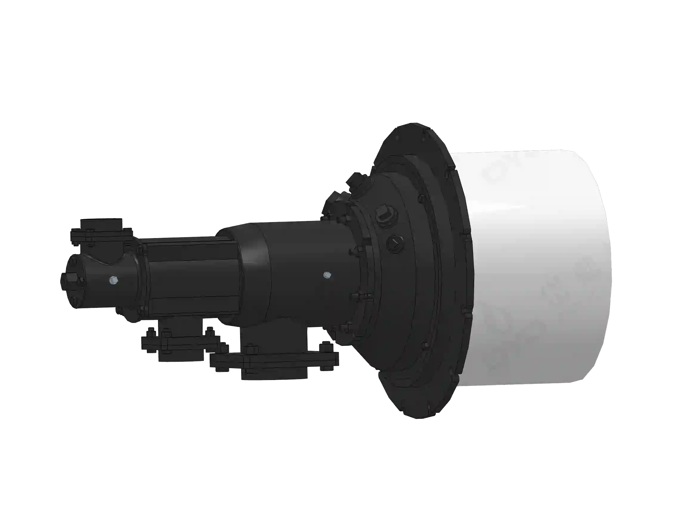
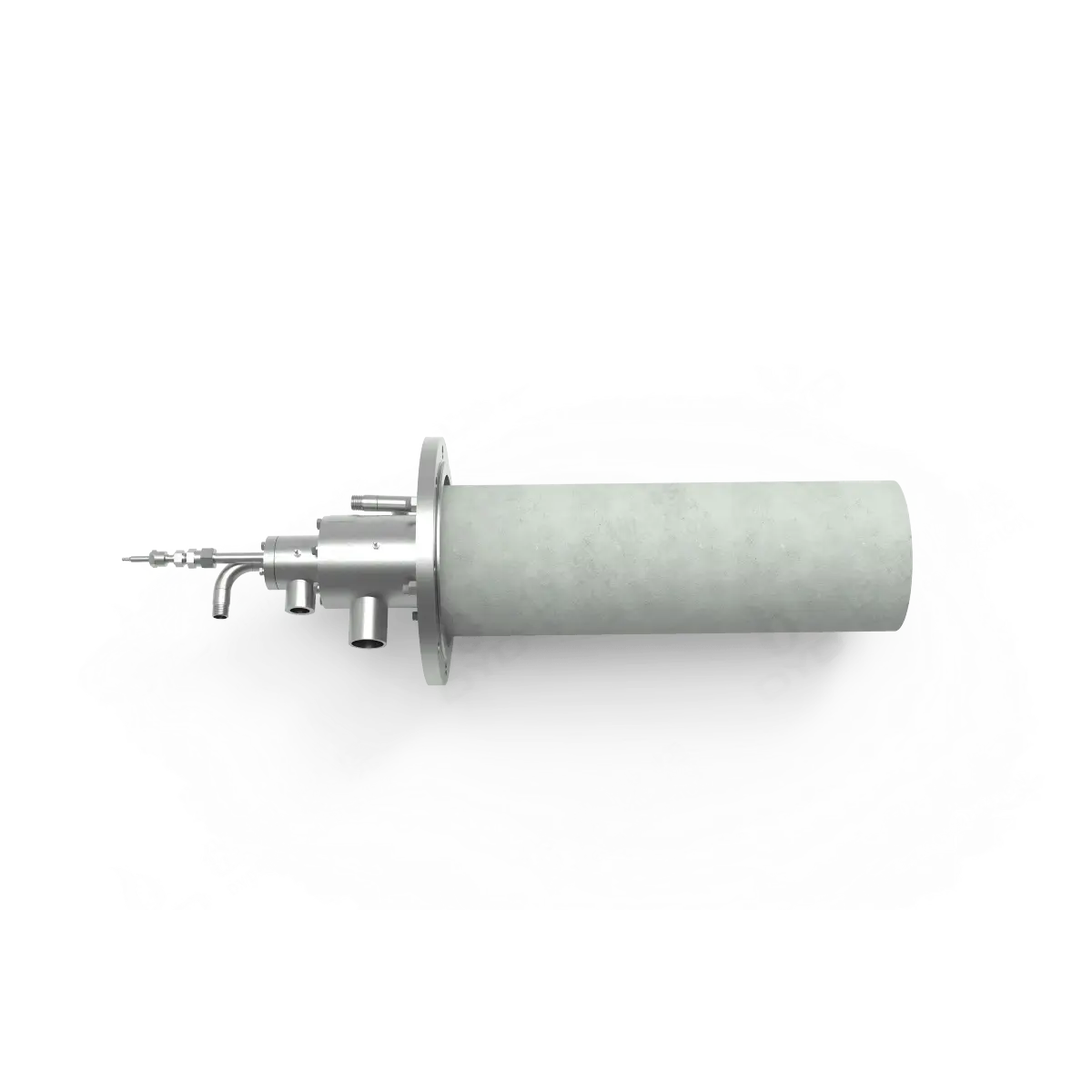
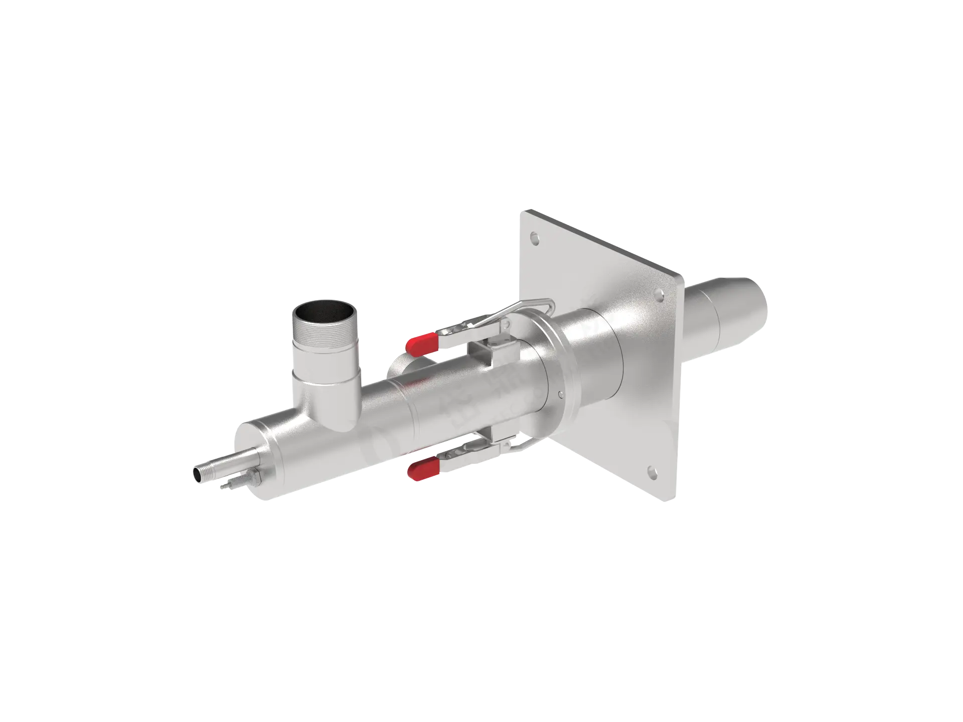
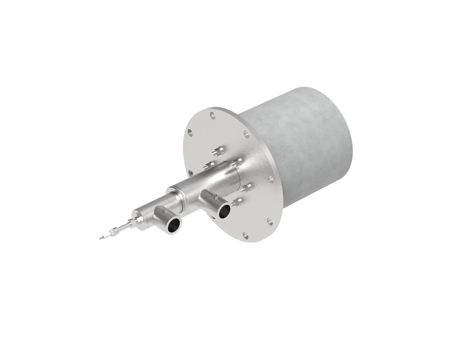
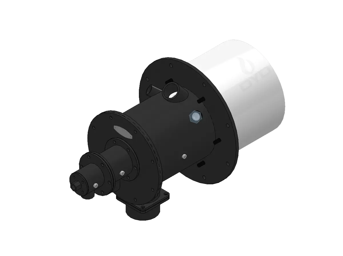
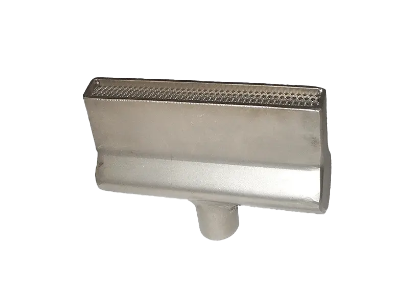
DYDTEC Combustion develops industrial burners and combustion-system solutions for different industrial heating applications.
Its product portfolio includes 100+ burner models covering 200+ application scenarios, allowing different burner configurations to be considered according to furnace geometry, thermal load, fuel conditions, and process requirements.
For OEM projects, burner arrangement can be evaluated together with:
Heat load
Furnace geometry
Flame characteristics
Burner capacity
Burner angle
Airflow
Exhaust
Temperature uniformity
Control strategy
DYDTEC Combustion was established in 2012, with R&D and manufacturing bases in Shanghai and Yangzhou and a factory area of approximately 11,000 m².
The company has a 98%+ self-developed system product rate, supporting applications where combustion equipment needs to be integrated with specific OEM equipment rather than treated as an independent standard component.
A burner arrangement is only effective when the supporting systems are compatible.
The combustion system may include:
Fuel supply
Combustion air
Ignition
Flame detection
Burner control
Furnace pressure control
Exhaust
Temperature measurement
If the burner arrangement changes, other system parameters may also need to be reviewed.
For example, adding burners increases the total combustion-air requirement and may affect exhaust flow.
Therefore:
Burner arrangement should be designed as part of the complete combustion system.
A practical approach is to focus on five areas.
Avoid both insufficient and excessive capacity.
Do not automatically divide total capacity equally among burners.
Use burner angle and position to promote useful heat transfer.
Avoid creating a direct high-temperature path from burner to exhaust.
Consider startup, normal operation, reduced load, and maximum load.
These principles can improve thermal utilization without simply increasing burner capacity.
Yes. Burner arrangement influences heat distribution, exhaust losses, temperature uniformity, and the amount of thermal energy effectively transferred to the process.
Not necessarily. The best configuration depends on furnace geometry, heat-load distribution, temperature requirements, and control strategy.
They can in suitable applications by distributing heat more effectively and allowing better zone control, but the actual result depends on the complete system design.
Yes. Poor spacing can create hot spots, cold zones, flame interaction, and inefficient heat distribution.
Yes. Burner angle changes flame trajectory and hot-gas circulation and can influence how much heat reaches the useful process area.
Yes. Properly distributed burners can provide more even thermal input and better temperature control.
Yes. Poor arrangements may allow high-temperature gases to reach the exhaust too quickly.
No. Capacity is important, but flame characteristics, arrangement, airflow, furnace geometry, and control are also critical.
Ideally, yes. Burner locations and flame characteristics should be considered during furnace design rather than added after the chamber has already been finalized.
Furnace dimensions, product position, production rate, heat load, fuel conditions, temperature requirements, exhaust conditions, and desired temperature uniformity are particularly important.
Yes. Complex or specialized equipment may require customized burner locations, angles, capacities, or multi-zone configurations.
Temperature mapping, combustion testing, airflow analysis, CFD where appropriate, and production-load testing can all be used.
Burner arrangement can have a significant effect on furnace efficiency because it determines how combustion energy is distributed and transferred to the process.
The relationship can be summarized as:
Burner Arrangement→ Flame Distribution→ Hot-Gas Circulation→ Heat Transfer→ Temperature Uniformity
→ Useful Heat→ Fuel Efficiency
A well-designed burner arrangement does not simply place burners where they can physically fit. It considers:
Furnace geometry
Heat load
Product position
Flame characteristics
Burner spacing
Burner angle
Airflow
Exhaust
Temperature zones
Part-load operation
Control strategy
For OEM manufacturers, this integrated approach is especially important because the combustion system becomes part of the equipment's overall thermal architecture.
Ultimately, the most efficient burner arrangement is not necessarily the one with the fewest burners or the highest burner capacity. It is the arrangement that delivers the required heat to the required locations with the least unnecessary thermal loss while maintaining stable and controllable operation.