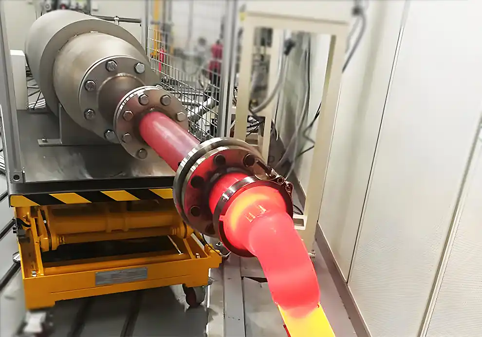
Uniform temperature distribution is one of the most important performance requirements for an industrial furnace.
A furnace may reach its target temperature quickly, but that does not necessarily mean the temperature is uniform throughout the heating chamber. One area may be significantly hotter than another, creating hot spots, cold zones, uneven heating, inconsistent product quality, and unnecessary energy consumption.
For many industrial processes, the real objective is not simply:
“How can the furnace reach the required temperature?”
but:
“How can the furnace maintain the required temperature consistently throughout the effective heating zone?”
Achieving this requires coordination between:
Heat Load + Burner + Flame Shape + Burner Arrangement + Airflow + Furnace Geometry + Exhaust + Temperature Control
There is no single adjustment that guarantees uniform temperature distribution. It is the result of the entire combustion and thermal system working together.
Uniform temperature distribution means that temperatures across the critical heating area remain within the acceptable range required by the process.
For example, a furnace may have a target temperature of 800°C.
If measurements show:
805°C in one area
798°C in another
802°C in another
795°C elsewhere
the temperature distribution may be sufficiently uniform for a particular process.
However, if the measurements are:
850°C
820°C
780°C
750°C
the furnace has a significant temperature gradient, even though its average temperature may still appear close to 800°C.
Therefore:
Average furnace temperature does not tell the whole story.
Engineers need to understand the temperature field across the actual product-heating area.
Temperature uniformity directly affects many industrial processes.
Depending on the application, uneven temperatures can cause:
Inconsistent product quality
Uneven drying
Incomplete heat treatment
Product deformation
Local overheating
Excessive oxidation
Inconsistent material properties
Longer processing times
Increased fuel consumption
Higher scrap rates
The importance of uniformity depends on the process.
A drying system may tolerate a wider temperature range than a precision heat-treatment furnace, while certain high-temperature processes may require particularly careful control of local heat flux.
Uneven temperature distribution usually results from one or more interacting factors.
Common causes include:
Incorrect burner selection
Poor burner positioning
Incorrect burner angle
Unsuitable flame length
Poor airflow distribution
Improper furnace geometry
Incorrect exhaust location
Excessive or insufficient combustion air
Inadequate gas circulation
Poor insulation
Improper product loading
Insufficient temperature-control zones
This means that temperature-uniformity problems should not automatically be blamed on the burner.
The entire combustion system needs to be evaluated.
The burner determines how thermal energy enters the furnace.
Important burner characteristics include:
Thermal capacity
Flame length
Flame width
Flame momentum
Flame shape
Mixing characteristics
Turndown ratio
Operating range
A burner that produces the correct heat input may still be unsuitable if its flame characteristics do not match the furnace.
For example:
Long flame + short chamber
may increase the risk of flame-wall interaction.
Conversely:
Short concentrated flame + large heating chamber
may produce excessive local heat near the burner while leaving distant areas underheated.
Therefore, burner selection should consider both thermal capacity and flame characteristics.
Burner position determines where heat enters the furnace.
A burner can be installed on:
Side walls
End walls
Roof
Floor
Multiple sides
Different heating zones
The correct position depends on the furnace geometry and process.
For a compact furnace, a centrally positioned burner may provide sufficient circulation.
For a long furnace, a single burner at one end may create a temperature gradient from the burner side to the exhaust side.
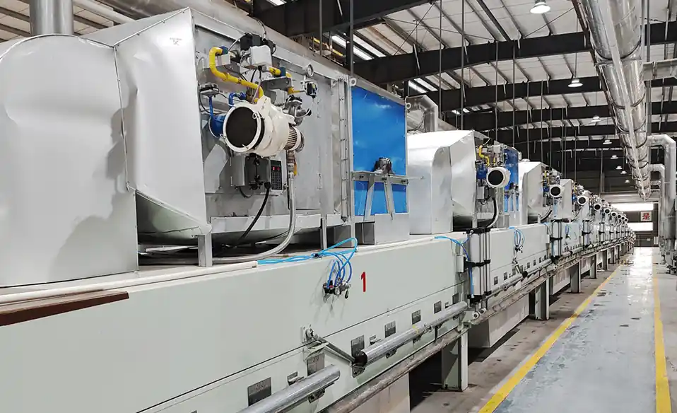
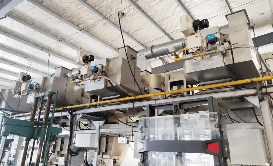
Multiple burners distributed along the furnace can sometimes provide better thermal coverage.
The key principle is:
Burner placement should follow the required heat distribution rather than simply the available installation space.
Burner angle determines the initial direction of the flame and combustion gases.
Changing the angle can alter:
Flame trajectory
Gas circulation
Heat-transfer area
Flame-wall distance
Product exposure
For example, burners can sometimes be arranged at different angles to encourage hot gases to circulate through the chamber instead of traveling directly toward the exhaust.
In some industrial furnaces, carefully arranged burners can create a circulating or swirling gas pattern.
The correct angle depends on the specific furnace geometry.
Flame shape determines where combustion energy is released.
Different burner designs can produce:
Long flames
Short flames
Wide flames
Narrow flames
High-momentum flames
Diffuse flames
The appropriate flame shape depends on the chamber.
A long heating chamber may require a flame with sufficient development length.
A compact chamber may require a shorter flame to avoid wall impingement.
A wide heating zone may require a broader heat-release pattern.
Therefore, flame shape should be treated as a design parameter, not simply a visual characteristic of the burner.
Airflow determines how hot combustion gases move through the furnace.
After combustion, thermal energy must be transported from the flame to the product and surrounding furnace surfaces.
Poor airflow can create:
Hot Zone → Weak Circulation → Cold Zone → Exhaust
Good airflow can help:
Distribute heat
Improve convective heat transfer
Reduce temperature gradients
Move hot gases into underheated areas
Improve overall thermal utilization
Airflow should therefore be considered together with:
Burner capacity
Burner angle
Furnace geometry
Exhaust flow
Furnace pressure
Not necessarily.
Increasing combustion air can change flame characteristics and gas velocity, but simply adding more air does not guarantee better temperature distribution.
Too much combustion air can:
Reduce flame temperature
Increase exhaust volume
Increase exhaust heat loss
Change flame shape
Affect furnace pressure
Too little air can cause:
Incomplete combustion
Increased CO
Flame instability
Poor combustion performance
The objective is to establish the appropriate combustion-air condition for the burner and process.
Furnace geometry has a major influence on heat distribution.
Important parameters include:
Chamber length
Chamber width
Chamber height
Internal volume
Surface area
Burner openings
Exhaust location
Internal structures can also influence gas flow.
Examples include:
Baffles
Shelves
Rollers
Product supports
Heat exchangers
Refractory structures
These components can redirect or obstruct hot-gas flow.
Therefore, a burner should not be selected without considering the physical environment in which its flame will operate.
Long furnaces often present a greater temperature-uniformity challenge.
A typical problem may look like:
High Temperature → Moderate Temperature → Low Temperature → Exhaust
This can happen when heat is introduced mainly from one end.
Possible approaches include:
Multiple burners
Multiple heating zones
Improved burner angles
Gas recirculation
Better exhaust positioning
Zone-based temperature control
The appropriate solution depends on the process.
A wide chamber provides a larger area that needs to receive heat.
If the burner produces a relatively narrow flame, the central region may become hotter while areas farther away remain cooler.
Possible solutions may include:
Multiple burners
Wider flame patterns
Distributed heating
Improved circulation
Optimized burner arrangement
The objective is to match the heat-release pattern to the effective heating area.
Height can influence natural convection and buoyancy.
Hot gases tend to rise, which can create vertical temperature differences in some furnace configurations.
For example, a vertical furnace may experience:
Hot Upper Zone
and
Cooler Lower Zone
if gas circulation is not adequately controlled.
Burner orientation, forced circulation, exhaust position, and chamber geometry can all influence this behavior.
The exhaust is not simply an outlet for combustion gases.
Its location influences the entire gas-flow pattern.
If the exhaust is positioned too close to the burner, hot gases may leave before sufficient heat transfer occurs.
If the exhaust is poorly positioned relative to the chamber geometry, it may create:
Cold zones
Uneven circulation
Strong local flow
Temperature gradients
A useful design concept is:
Burner → Flame → Hot-Gas Circulation → Product → Exhaust
The exhaust should be considered together with the burner location.
Furnace pressure affects gas movement and can influence combustion stability.
Depending on the application, a furnace may operate under:
Slight negative pressure
Near-atmospheric pressure
Slight positive pressure
Incorrect pressure can contribute to:
Cold-air infiltration
Excessive exhaust
Combustion instability
Temperature fluctuations
Maintaining appropriate furnace pressure is therefore part of maintaining a stable thermal environment.
Heat load determines how much thermal energy the furnace needs.
But heat load is not necessarily distributed evenly throughout the chamber.
A furnace may have:
High heat demand near the product entrance
Lower heat demand in a holding zone
Higher demand in a drying zone
Different requirements during startup and steady operation
This is why multi-zone combustion systems are often used.
Each zone can be designed around its own thermal requirement.
A multi-zone furnace allows thermal input to be distributed according to process requirements.
For example:
Lower temperature, gradually increasing heat input.
Higher thermal input.
Lower heat input to maintain the required temperature.
Controlled thermal conditions according to the process.
Each zone can have independent:
Burner capacity
Temperature measurement
Fuel control
Air control
Operating strategy
This can provide more precise temperature management than treating the entire furnace as one thermal zone.
Not necessarily.
Potential advantages:
Simpler installation
Fewer components
Centralized control
Potential limitations:
Concentrated heat input
Less flexibility in heat distribution
Greater dependence on furnace circulation
Potential advantages:
Distributed heat input
Multiple heating zones
Better flexibility
Independent control
Potential limitations:
More complex piping
More control components
More complicated commissioning
The appropriate solution depends on furnace geometry, heat load, process requirements, and temperature-uniformity targets.
Yes.
Hot-gas recirculation can help redistribute thermal energy within the furnace.
Instead of allowing hot gases to move directly from the burner to the exhaust:
Burner → Hot Gas → Recirculation → Product → Exhaust
This can increase gas mixing and reduce temperature differences.
However, recirculation needs to be designed according to:
Furnace geometry
Gas temperature
Fan capacity
Pressure
Process requirements
Safety requirements
Product loading can significantly change airflow and heat transfer.
When the furnace is heavily loaded, products may:
Block gas passages
Increase thermal demand
Change circulation patterns
Create shadow zones
Increase pressure drop
A furnace that appears uniform when empty may become significantly less uniform under production conditions.
Therefore, commissioning and testing should ideally include realistic product loading.
The temperature experienced by a product depends on where it is located.
Products close to the flame may receive stronger thermal radiation or convection.
Products near walls may experience different heat-transfer conditions from those in the center.
Products near the exhaust may experience different gas temperatures than products near the burner.
Therefore, product placement should be considered when determining:
Burner location
Burner angle
Airflow direction
Exhaust location
Heating zones
Drying requires more than simply supplying hot air.
The system needs to deliver the appropriate combination of:
Air temperature
Air velocity
Air volume
Recirculation
Exhaust
Residence time
A typical system is:
Burner → Hot Air → Air Distribution → Product → Moist Exhaust
If the hot air is distributed unevenly, some product may become overdried while other areas retain excessive moisture.
For this reason, burner performance and hot-air distribution should be evaluated together.
For heat treatment, temperature uniformity often needs to be controlled across the actual product zone.
Important measures include:
Proper burner arrangement
Suitable flame characteristics
Multiple heating zones
Gas circulation
Correct exhaust positioning
Adequate insulation
Accurate temperature measurement
Closed-loop temperature control
The goal is to ensure that different parts of the product experience sufficiently similar thermal conditions.
Melting furnaces require careful heat distribution because excessive local temperatures can create problems even when the overall furnace temperature appears acceptable.
The combustion system should consider:
Burner position
Flame direction
Flame length
Heat-release intensity
Furnace circulation
Material loading
Exhaust flow
The goal is to transfer heat effectively without creating unnecessary local thermal peaks.
Temperature mapping is one of the most useful methods.
Instead of measuring temperature at only one point, sensors are placed at multiple locations.
Measurements can be taken at:
Furnace corners
Center
Near burners
Near exhaust
Upper areas
Lower areas
Product positions
The results can then be compared to identify temperature gradients.
A basic evaluation can determine:
Maximum Temperature − Minimum Temperature
But more detailed analysis may also examine:
Average temperature
Standard deviation
Zone-to-zone differences
Product temperature
Temperature stability over time
Empty-furnace testing can be useful for understanding the basic thermal behavior of the combustion system.
However, an empty furnace does not necessarily represent actual production conditions.
Product loading can change:
Heat absorption
Airflow
Circulation
Pressure
Thermal inertia
Therefore, production-load testing is also important when product quality depends on temperature uniformity.
Temperature control should respond to actual furnace conditions.
A basic control loop can be represented as:
Temperature Sensor → Controller → Burner Output → Furnace Temperature → Sensor
For multi-zone systems:
Zone Sensor → Zone Controller → Zone Burner → Zone Temperature
This allows thermal input to be adjusted according to the actual process demand.
However, good control cannot fully compensate for fundamentally poor burner placement or airflow design.
The mechanical and combustion design should first provide a reasonable thermal field.
Yes, but insulation primarily reduces heat loss rather than directly correcting poor gas circulation.
Good insulation can:
Reduce wall heat loss
Reduce external temperature
Improve energy efficiency
Reduce the thermal load required to maintain temperature
However, if the main problem is a hot zone near the burner and a cold zone near the exhaust, adding insulation alone will not solve the underlying airflow problem.
A systematic approach is more effective than changing the burner immediately.
Identify exactly where hot and cold zones occur.
Verify:
Fuel pressure
Air pressure
Flame stability
Burner output
Turndown
Look for:
Flame impingement
Poor flame clearance
Unsuitable firing direction
Evaluate:
Combustion air
Process air
Recirculation
Exhaust flow
Confirm that the furnace operates within the intended pressure range.
Verify that the exhaust arrangement is not creating an unfavorable flow path.
Test under realistic operating conditions.
Only after identifying the underlying cause should engineers modify:
Burner angle
Burner output
Airflow
Burner arrangement
Exhaust
Control parameters
OEM manufacturers should provide information about:
Length
Width
Height
Internal volume
Insulation
Internal structures
Required temperature
Heating time
Production rate
Product characteristics
Dimensions
Position
Mass
Moisture content where applicable
Fuel type
Fuel pressure
Required heat load
Combustion-air conditions
Exhaust location
Exhaust flow
Exhaust pressure
Target temperature
Allowable temperature difference
Required temperature zones
This information helps determine whether the system should use one burner, multiple burners, distributed heating, recirculation, or another configuration.
DYDTEC Combustion develops industrial burners and combustion-system solutions for different industrial heating applications.
Its product portfolio includes 100+ burner models covering 200+ application scenarios, allowing different combustion configurations to be considered according to furnace geometry, thermal load, fuel conditions, and process requirements.
For OEM equipment, temperature-uniformity design can be evaluated together with:
Burner capacity
Flame shape
Burner position
Burner angle
Airflow
Furnace geometry
Exhaust conditions
Heating zones
Temperature-control strategy
DYDTEC Combustion was established in 2012, with R&D and manufacturing bases in Shanghai and Yangzhou and a factory area of approximately 11,000 m².
Its combustion-system development approach is particularly relevant to OEM projects where the burner needs to be integrated into equipment with specific thermal and mechanical constraints.
A standard burner may provide sufficient thermal capacity but still produce an unsuitable heat distribution pattern.
Customization or system-level configuration may be necessary when the furnace has:
Unusual dimensions
Limited burner installation space
Multiple heating zones
Complex internal structures
Special flame requirements
Strict temperature-uniformity requirements
Unusual fuel or air conditions
DYDTEC Combustion has a 98%+ self-developed system product rate, supporting applications where combustion equipment needs to be coordinated with specific OEM equipment rather than selected solely by nominal capacity.
The most important principle is:
Do not treat temperature uniformity as a burner-only problem.
Uniform temperature distribution depends on the entire thermal system.
The relationship can be summarized as:
Heat Load
↓
Burner Selection
↓
Flame Characteristics
↓
Burner Arrangement
↓
Airflow
↓
Furnace Geometry
↓
Exhaust
↓
Temperature Control
↓
Product Temperature
Changing one element can affect the others.
For example, increasing burner capacity without changing airflow may create a stronger hot zone rather than improving uniformity.
The most effective approach is to coordinate burner selection, flame characteristics, burner arrangement, airflow, furnace geometry, exhaust, and temperature control as one integrated system.
No. Multiple burners can distribute heat more effectively when correctly arranged, but poor placement can create additional hot spots.
Yes. Burner angle changes flame trajectory and hot-gas circulation and can sometimes significantly improve heat distribution.
Yes. Airflow controls how hot gases circulate and how thermal energy is transported through the chamber.
Yes. Average temperature can hide significant local temperature differences.
Perform temperature mapping using multiple measurement points across the actual product-heating area.
Yes. Chamber dimensions, internal structures, burner locations, and exhaust positions all influence the thermal field.
It can. Pressure affects gas movement, leakage, exhaust behavior, and combustion stability.
Insulation can reduce heat loss, but it cannot necessarily correct poor airflow, burner placement, or gas circulation.
The answer depends on furnace geometry, heat load distribution, temperature-uniformity requirements, and control strategy.
Uneven temperature and airflow can cause different parts of the product to dry at different rates, resulting in inconsistent residual moisture.
Different temperatures can produce different thermal histories, potentially affecting the properties and consistency of treated materials.
Ideally during the early equipment-design stage, before the burner arrangement, airflow system, and furnace geometry are finalized.
Furnace dimensions, product position, production rate, required temperature, heat load, fuel conditions, combustion-air conditions, exhaust conditions, and allowable temperature variation are particularly useful.
Achieving uniform temperature distribution is not simply a matter of selecting a burner with the correct thermal capacity.
A stable and uniform thermal field is created by the interaction of:
Burner→ Flame→ Airflow→ Gas Circulation→ Furnace Geometry→ Exhaust→ Temperature Control→ Product
The most common mistake is to look at the furnace as a single temperature point.
In reality, the product experiences a three-dimensional temperature and airflow environment.
For OEM equipment, the better approach is to design the combustion system around the actual product, process, furnace geometry, and heat-load distribution from the beginning.
Ultimately:
Uniform temperature distribution is achieved not by making every part of the furnace hotter, but by controlling where, how, and how evenly thermal energy is delivered.