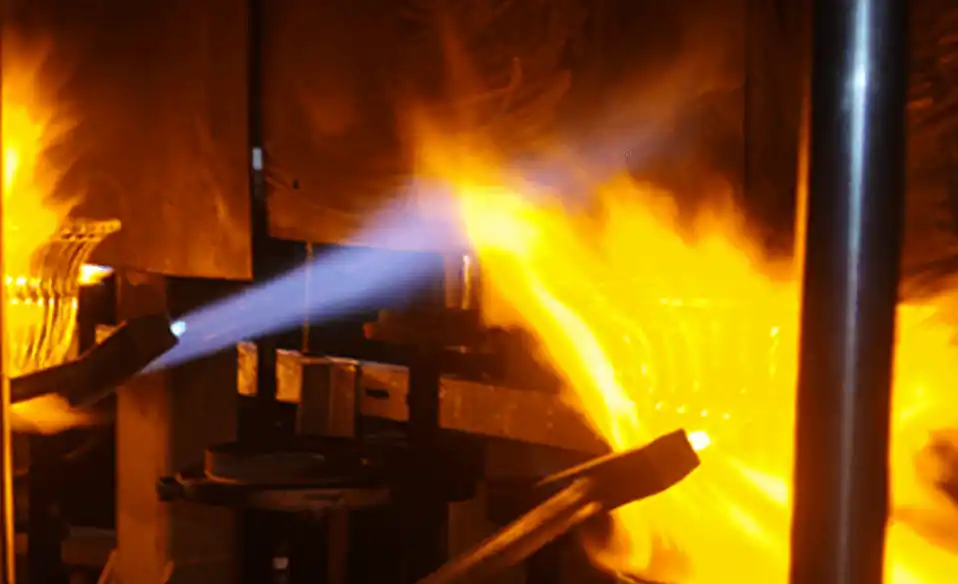
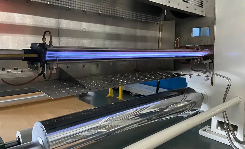
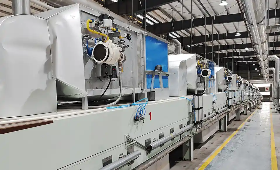
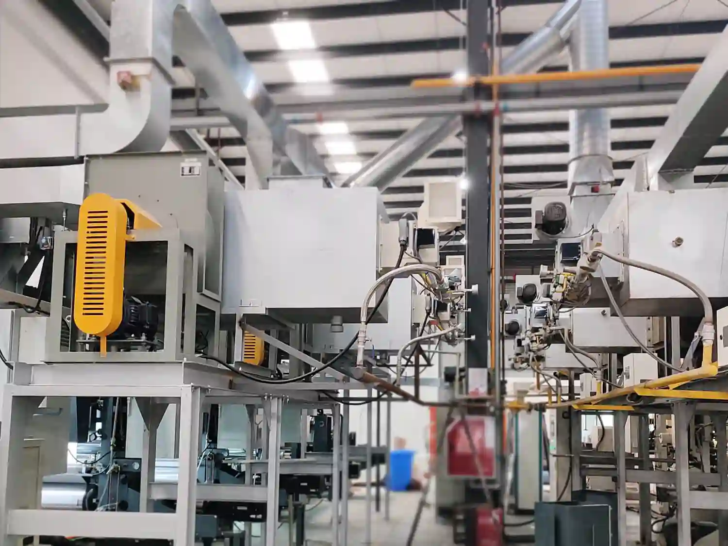
Heat distribution is one of the most important factors determining whether an industrial heating process produces consistent product quality.
A furnace can reach the required average temperature and still produce defective or inconsistent products if heat is distributed unevenly.
For example, a furnace may be set to 800°C, but one area may be significantly hotter while another remains relatively cold. The temperature shown by a single thermocouple may look correct, yet products positioned in different areas of the furnace can experience different thermal histories.
This can lead to:
Uneven heating
Overheating
Underheating
Different treatment results
Uneven drying
Material deformation
Surface defects
Inconsistent mechanical properties
Increased scrap rates
The key principle is:
Furnace temperature tells you how hot the system is; heat distribution tells you whether the product is being heated correctly.
For industrial equipment and OEM systems, burner selection should therefore consider not only thermal capacity, but also flame characteristics, burner arrangement, airflow, furnace geometry, exhaust flow, and the required temperature distribution.
Heat distribution describes how thermal energy is distributed throughout the usable heating space.
In an ideal furnace, the temperature field should be sufficiently uniform for the specific process.
However, real furnaces can contain:
Hot zones
Cold zones
Temperature gradients
Recirculation zones
Dead zones
Localized high-temperature areas
The actual thermal field depends on the interaction between:
Burner + Flame + Airflow + Furnace Geometry + Product + Exhaust
This means that heat distribution is a system-level characteristic, rather than a property determined by the burner alone.
Most industrial processes do not simply require the product to reach a particular temperature.
They require the product to experience a controlled thermal history.
That thermal history can include:
Heating rate
Maximum temperature
Holding time
Cooling rate
Temperature uniformity
Exposure to hot gases
Local temperature differences
If two products are exposed to different thermal conditions, they may behave differently even when they come from the same production line.
For this reason:
Temperature uniformity is often a product-quality requirement, not merely a furnace-performance indicator.
A hot zone occurs when a region of the furnace receives significantly more thermal energy than the surrounding areas.
Possible causes include:
Flame impingement
Excessive flame intensity
Poor burner positioning
Excessive burner momentum
Insufficient gas circulation
Incorrect burner angle
Poor chamber geometry
Inadequate temperature control
The consequences depend on the product.
Potential problems include:
Surface overheating
Material deformation
Excessive oxidation
Localized melting
Uneven drying
Thermal damage
Changes in material properties
In high-temperature processes, even a relatively small localized temperature difference can become significant.
A cold zone is an area where the product receives insufficient thermal energy.
This can occur when:
Hot gases do not circulate effectively
Burner coverage is inadequate
Exhaust flow pulls heat away too quickly
Furnace geometry creates dead zones
Burner arrangement does not match the chamber
Product loading obstructs gas circulation
Typical results include:
Incomplete heating
Insufficient drying
Inadequate heat treatment
Longer processing times
Product-to-product variation
Reduced production capacity
A furnace may therefore have a correct average temperature while still producing cold-zone defects.
No.
Average temperature can hide significant local differences.
Consider a simplified example:
Zone A: 820°C
Zone B: 800°C
Zone C: 780°C
The average may still appear close to the 800°C setpoint.
However, if the product requires tight temperature uniformity, the 40°C difference between the hottest and coldest areas may be unacceptable.
Therefore, engineers should consider:
Average temperature
Maximum temperature
Minimum temperature
Temperature difference
Temperature distribution
Product temperature
rather than relying on a single measurement.
Temperature uniformity describes how closely temperatures across the required process area remain to the target condition.
A simplified representation is:
Temperature Uniformity = Maximum Temperature − Minimum Temperature
The acceptable temperature difference depends entirely on the process.
A drying process may tolerate a wider temperature range than a precision heat-treatment process.
Therefore, there is no universal definition of "good" temperature uniformity.
The required uniformity should be established according to the product and process.
Burner position determines where thermal energy enters the furnace.
A burner can be installed:
On a side wall
On an end wall
On the roof
On the floor
At multiple locations
Along several heating zones
The correct arrangement depends on furnace geometry and process requirements.
For example, placing a single high-capacity burner at one end of a long chamber may create a strong temperature gradient.
Using multiple burners distributed along the chamber may provide better control of the thermal field.
Therefore:
Burner location is a heat-distribution decision, not simply an installation decision.
Burner angle determines the initial direction of the flame and combustion gases.
A change in burner angle can affect:
Flame trajectory
Flame-wall clearance
Gas circulation
Heat-transfer area
Product exposure
A burner firing directly toward a product may create a localized hot area.
A different firing angle may direct the flame along the chamber and promote wider heat distribution.
In some furnaces, burners are arranged to create a circulating or swirling gas flow.
The appropriate angle depends on the chamber geometry and process.
Flame length determines where much of the combustion heat is released.
If the flame is too long for the chamber, it may interact with:
Furnace walls
Refractory
Product
Internal structures
If the flame is too short, heat release may become concentrated near the burner.
Neither situation is automatically desirable.
The objective is to match:
Flame Length + Chamber Length + Product Position + Exhaust Location
so that heat is distributed appropriately.
Flame shape determines the spatial distribution of combustion energy.
Different burner designs can produce different flame characteristics, including:
Long flames
Short flames
Narrow flames
Wide flames
High-momentum flames
Diffuse flames
The correct flame shape depends on the application.
For example:
A long chamber may require extended flame development.
A compact chamber may require a shorter flame.
A wide heating zone may benefit from broader heat distribution.
A sensitive product may require reduced direct flame exposure.
Therefore, flame shape should be considered during burner selection.
Airflow determines how combustion gases move through the furnace.
After combustion occurs, hot gases must travel through the chamber and transfer heat to the product.
Poor airflow can create:
Hot Zone → Poor Circulation → Cold Zone → Exhaust
Good airflow design can improve:
Gas circulation
Convective heat transfer
Temperature uniformity
Heat utilization
Important airflow parameters include:
Combustion-air flow
Air velocity
Recirculation
Exhaust flow
Furnace pressure
The airflow pattern should be evaluated together with the burner and furnace geometry.
Furnace geometry strongly influences the thermal field.
Important dimensions include:
Length
Width
Height
Volume
Surface area
Burner opening location
Exhaust location
Internal structures can also affect heat distribution.
For example:
Baffles
Shelves
Rollers
Heat exchangers
Product supports
Refractory structures
can change the path of hot gases.
This is why two furnaces with the same burner and thermal capacity can still produce different temperature distributions.
The exhaust determines where combustion gases leave the furnace.
If the exhaust is too close to the burner, hot gases may leave before sufficient heat transfer occurs.
If the exhaust is positioned poorly relative to the chamber geometry, it can create:
Uneven circulation
Cold zones
Excessive local flow
Temperature gradients
Therefore, exhaust design should be considered together with burner placement.
A useful system-level relationship is:
Burner → Flame → Hot-Gas Flow → Product → Exhaust
Changing any one of these elements can influence the overall thermal field.
The product itself changes the flow and heat-transfer environment.
Large quantities of material can:
Block airflow
Increase thermal demand
Change gas circulation
Create shadow zones
Increase pressure drop
A furnace that performs well when empty may behave differently under full production conditions.
For OEM equipment, thermal testing should therefore consider realistic production loading rather than relying only on an empty-furnace test.
Products positioned close to a burner may receive more direct radiant or convective heat.
Products farther away may experience different gas temperatures and flow conditions.
This can create differences between:
Front and rear products
Upper and lower products
Center and edge products
Near-wall and central products
Product positioning should therefore be considered when designing burner arrangements and airflow paths.
Drying is particularly sensitive to heat distribution.
The drying process depends on both temperature and airflow.
If one area receives hotter air and another receives cooler air, moisture removal may occur at different rates.
Possible results include:
Over-drying
Under-drying
Uneven residual moisture
Longer drying time
Product quality variation
For drying systems, a useful relationship is:
Burner → Hot Air → Air Distribution → Product → Moist Exhaust
The burner must therefore be integrated with the hot-air circulation system rather than evaluated independently.
Heat-treatment processes often require controlled thermal cycles.
The product may need to:
Heat at a defined rate
Reach a target temperature
Remain within a specified temperature range
Maintain the required holding time
Cool under controlled conditions
If different parts of the furnace have different temperatures, products may experience different treatment histories.
This can influence properties such as:
Hardness
Strength
Microstructure
Dimensional stability
The actual effects depend on the material and process.
Aluminum and other metals can be sensitive to localized overheating.
Poor heat distribution can result in:
Excessive surface temperature
Uneven melting
Increased oxidation
Longer melting time
Thermal stress
For melting applications, the combustion system should therefore be designed to transfer heat effectively without creating unnecessary local thermal peaks.
Burner position, flame characteristics, furnace geometry, and heat circulation all need to be considered.
Continuous furnaces often require different thermal conditions in different sections.
A typical system may contain:
Preheating → Heating → Holding → Final Treatment → Cooling
Each section may have a different thermal requirement.
Using the same burner configuration throughout the entire furnace is not always optimal.
Different zones may require different:
Burner capacities
Burner quantities
Flame characteristics
Airflow rates
Control strategies
This is one reason multi-zone combustion systems are widely used in industrial heating equipment.
Not automatically.
Adding more burners can provide more distributed heat input, but it can also create new challenges.
If burners are poorly positioned, the system may develop:
Overlapping flames
Local hot spots
Excessive combustion-air demand
Uneven pressure
Complicated control
The objective is not to maximize the number of burners.
It is to achieve the required thermal distribution and controllability.
Sometimes, but not always.
A single burner can be effective when:
The chamber is compact
The flame matches the chamber geometry
Gas circulation is favorable
The heat load is relatively centralized
Multiple burners may be more suitable when:
The furnace is long
The heating area is large
Multiple zones are required
Temperature uniformity is critical
Heat input needs to be distributed
The correct solution depends on the thermal field rather than simply the total heat load.
Several methods can be used.
Multiple temperature sensors can be placed throughout the furnace to identify hot and cold zones.
Infrared measurements can help identify surface-temperature differences where appropriate.
Airflow and exhaust behavior can be evaluated to identify circulation problems.
For complex systems, numerical modeling can help analyze:
Flow patterns
Temperature fields
Recirculation
Flame behavior
Heat transfer
Ultimately, product testing under actual operating conditions is important because furnace temperature uniformity does not always directly translate into product uniformity.
A temperature mapping test measures temperature at multiple locations under defined operating conditions.
Instead of asking:
"Is the furnace temperature 800°C?"
engineers can ask:
"What is the temperature at every critical product location?"
This can reveal:
Maximum temperature
Minimum temperature
Average temperature
Temperature gradients
Zone-to-zone differences
Temperature mapping is particularly useful during commissioning and process validation.
A combustion system should ideally be evaluated under several operating conditions.
Check:
Flame stability
Minimum temperature control
Burner turndown
Check:
Temperature uniformity
Fuel consumption
Process stability
Check:
Maximum temperature
Flame clearance
Furnace pressure
Exhaust performance
Check:
Product temperature
Product quality
Actual heat distribution
Testing only at one operating condition may not reveal the full behavior of the system.
The most common causes include:
Poor burner positioning
Incorrect burner angle
Inappropriate flame length
Incorrect burner capacity
Poor airflow distribution
Incorrect exhaust location
Poor furnace geometry
Inadequate insulation
Excessive product loading
Poor temperature-control strategy
In many cases, several factors interact.
For example:
Incorrect Burner Position + Poor Airflow + Poor Exhaust Design
can produce much greater temperature differences than any one factor alone.
Heat distribution should be considered before the furnace is fully designed.
A practical design sequence is:
Process Requirements
↓
Product Characteristics
↓
Heat-Load Calculation
↓
Furnace Geometry
↓
Burner Selection
↓
Burner Position & Angle
↓
Airflow Design
↓
Exhaust Design
↓
Temperature Control
↓
Thermal Testing
This integrated approach reduces the risk of treating the burner as an isolated component.
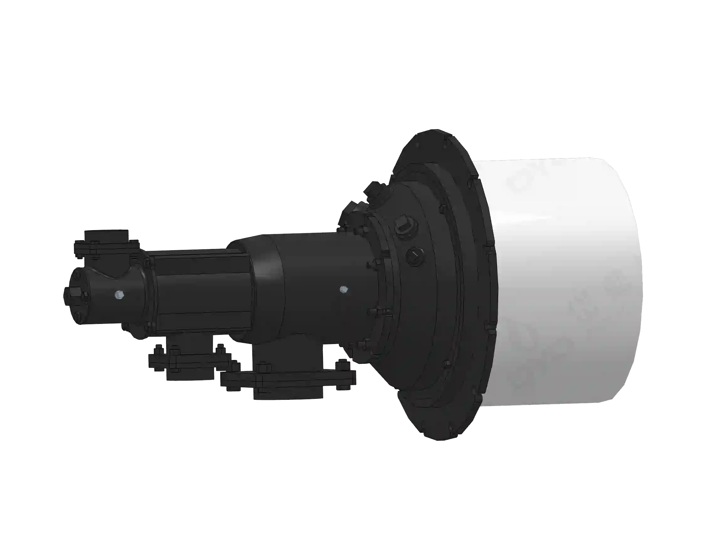
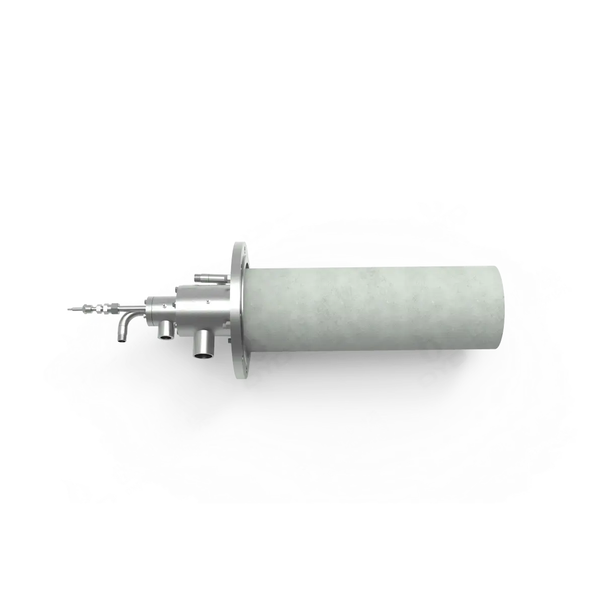
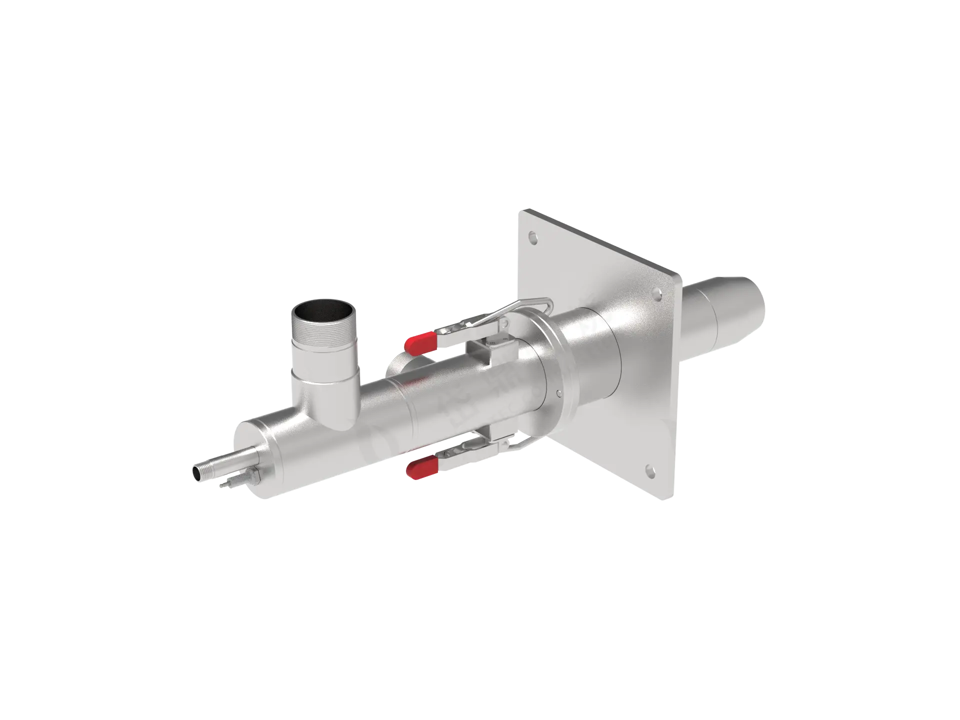
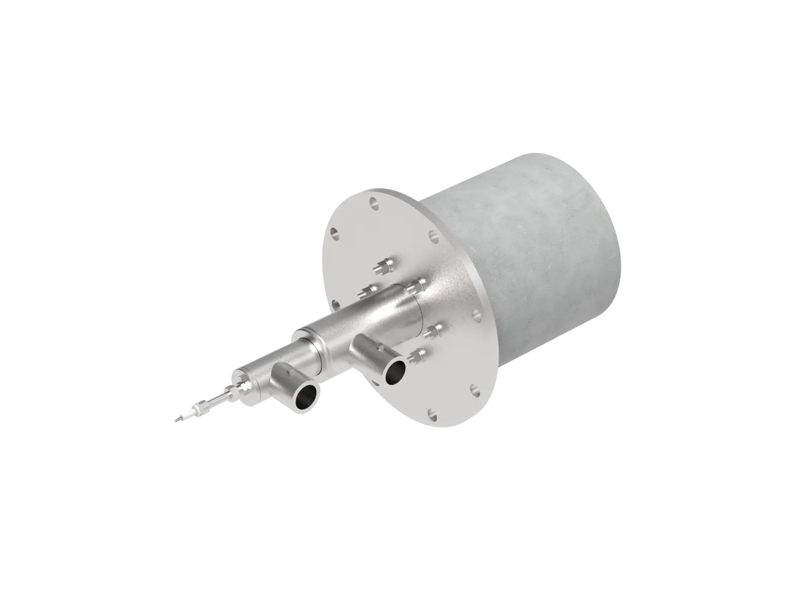
DYDTEC Combustion develops industrial burners and combustion-system solutions for different industrial heating applications.
Its product portfolio includes 100+ burner models covering 200+ application scenarios, allowing different burner configurations to be considered for different furnace structures, thermal loads, fuels, and process requirements.
For OEM equipment, heat distribution can be considered together with:
Furnace geometry
Burner capacity
Flame shape
Burner angle
Burner position
Combustion-air conditions
Exhaust conditions
Temperature-control requirements
DYDTEC Combustion was established in 2012, with R&D and manufacturing bases in Shanghai and Yangzhou and a factory area of approximately 11,000 m².
Its combustion-system solutions are intended for applications where burner performance needs to be coordinated with the actual equipment and thermal process rather than selected solely according to nominal burner capacity.
A standard burner may provide sufficient heat input but still fail to produce the required heat distribution.
Customization may become necessary when an OEM furnace has:
Unusual chamber dimensions
Limited installation space
Complex internal structures
Multiple heating zones
Special flame requirements
High temperature-uniformity requirements
Special fuel conditions
Non-standard burner angles
In these situations, the combustion system may need to be adapted to the equipment.
DYDTEC Combustion has a 98%+ self-developed system product rate, supporting applications where burner configuration and combustion-system integration need to be matched to specific equipment requirements.
A burner is not simply a device that produces a specified amount of heat.
Its characteristics influence:
Where heat is released
How the flame develops
How hot gases move
How heat reaches the product
How temperature is controlled
Therefore, burner selection should begin with the product and process requirements, not only the desired burner capacity.
The right question is not simply:
"How many kW does the furnace need?"
It is also:
"How should those kW be distributed throughout the furnace?"
Because products experience the actual local temperature and airflow conditions around them, not the average furnace temperature.
Yes. A furnace can reach its setpoint while having significant hot and cold zones.
Common causes include burner position, flame characteristics, airflow, furnace geometry, exhaust location, product loading, and control strategy.
Yes. Burner position determines where combustion energy enters the furnace and can influence local temperature and heat-transfer patterns.
Yes. Burner angle changes flame trajectory and hot-gas circulation, which can alter heat distribution.
Not by itself. Capacity determines how much thermal energy can be supplied, while burner design and furnace configuration determine how that energy is distributed.
Not necessarily. More burners can improve heat distribution when correctly designed, but poor burner placement can create additional hot spots.
Airflow carries combustion heat through the furnace and influences circulation, convection, temperature uniformity, and exhaust behavior.
Yes. Chamber length, width, height, internal structures, burner openings, and exhaust locations all influence gas flow and temperature distribution.
Temperature mapping, multiple thermocouples, thermal imaging where appropriate, airflow analysis, modeling, and production testing can all be used.
No. Maximum, minimum, local temperatures, temperature gradients, and product temperature should also be considered when uniformity is important.
Uneven hot-air distribution can cause different parts of the product to dry at different rates, resulting in uneven moisture content.
Uneven temperature can expose different products or different parts of a product to different thermal histories, potentially affecting treatment results and material properties.
Ideally during the early design stage, before burner position, furnace geometry, airflow, and exhaust arrangements are finalized.
Useful information includes furnace dimensions, product location, production rate, required temperature, heat-load data, burner installation location, airflow, exhaust conditions, and temperature-uniformity requirements.
Heat distribution is a critical link between combustion performance and product quality.
A burner may provide the required thermal capacity, but the final product quality depends on how that heat is distributed throughout the actual process space.
The key relationship is:
Burner→ Flame→ Airflow→ Hot-Gas Circulation→ Heat Distribution→ Product Temperature→ Product Quality
This is why industrial furnace design should not focus only on burner capacity or furnace operating temperature.
A more complete approach evaluates:
Heat load
Burner capacity
Flame characteristics
Burner position
Burner angle
Furnace geometry
Airflow
Exhaust
Temperature control
Product loading
as one integrated system.
For OEM manufacturers, involving the combustion-system designer early in equipment development can make it easier to align the burner with the furnace geometry and the actual thermal requirements of the product.
Ultimately, the goal of a combustion system is not simply to make the furnace hot—it is to deliver the right amount of heat to the right place, at the right temperature, for the right amount of time.