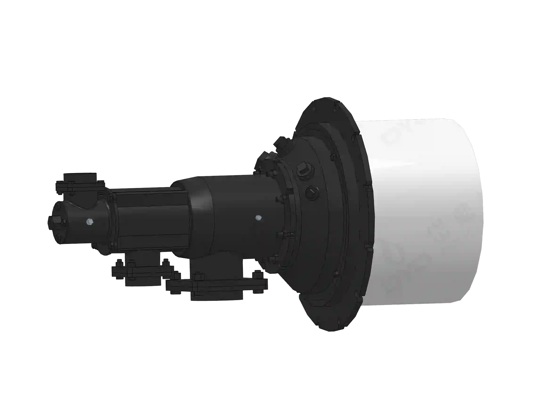
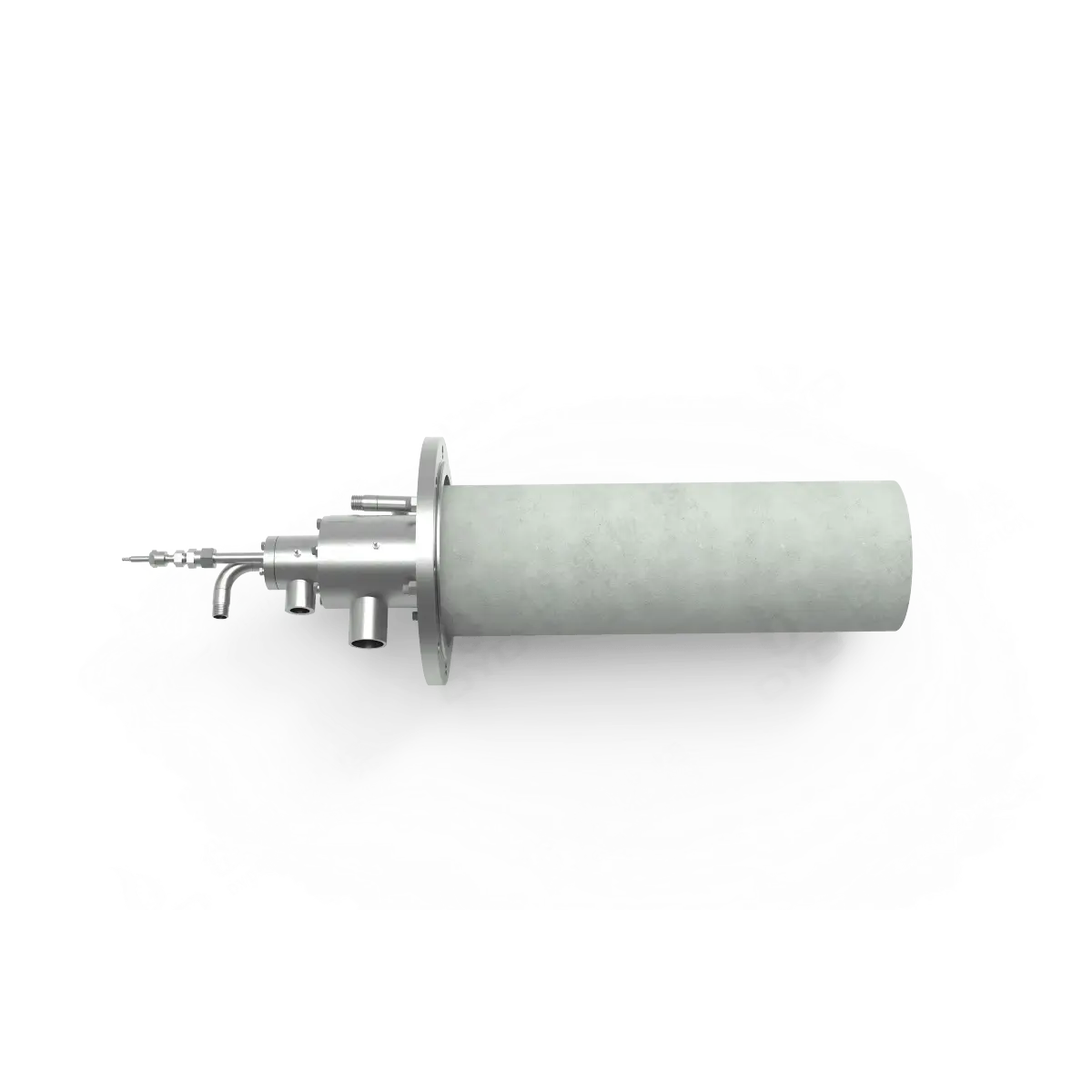
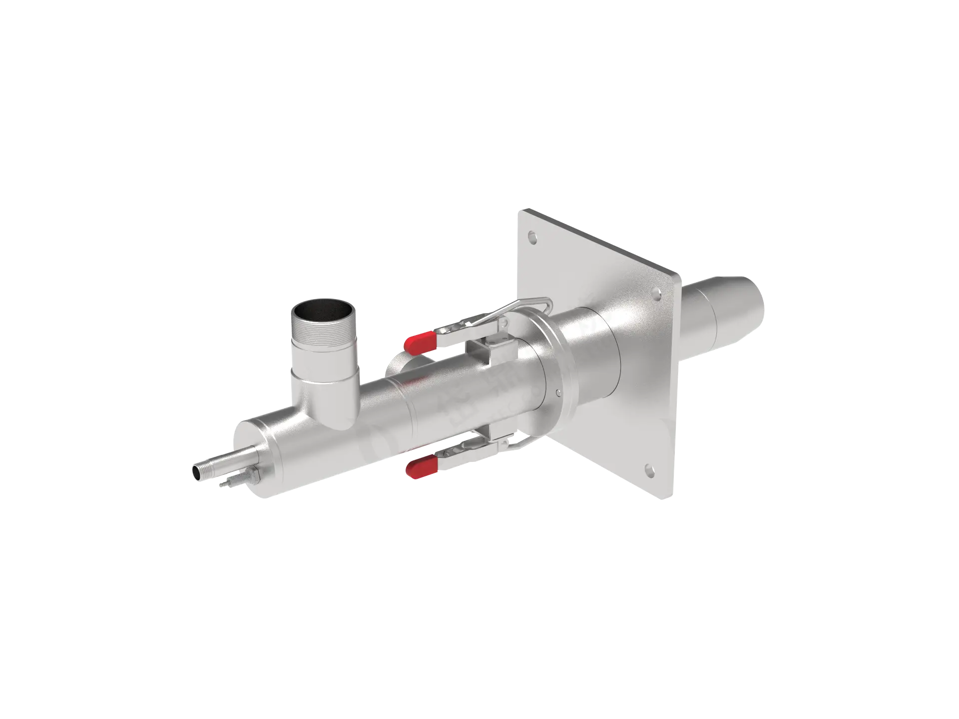
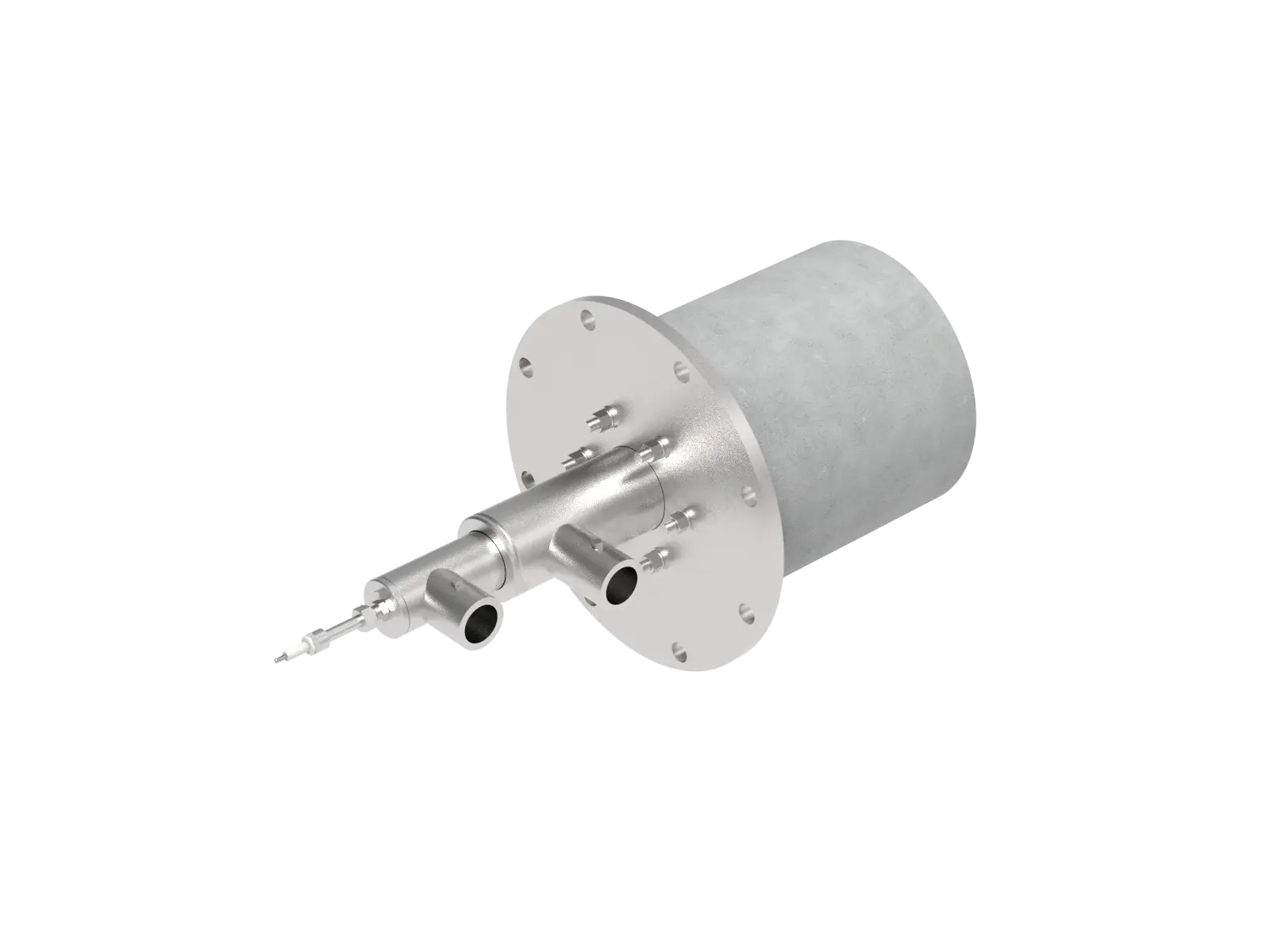
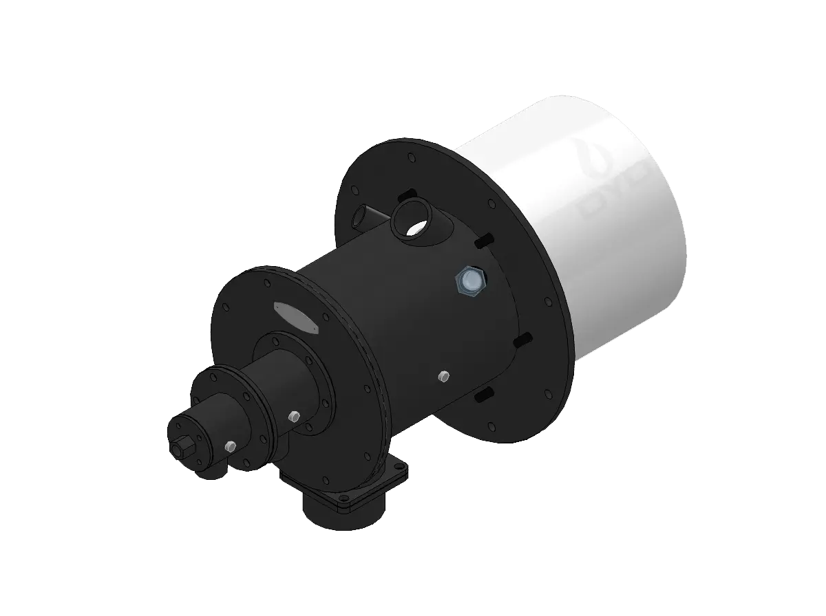
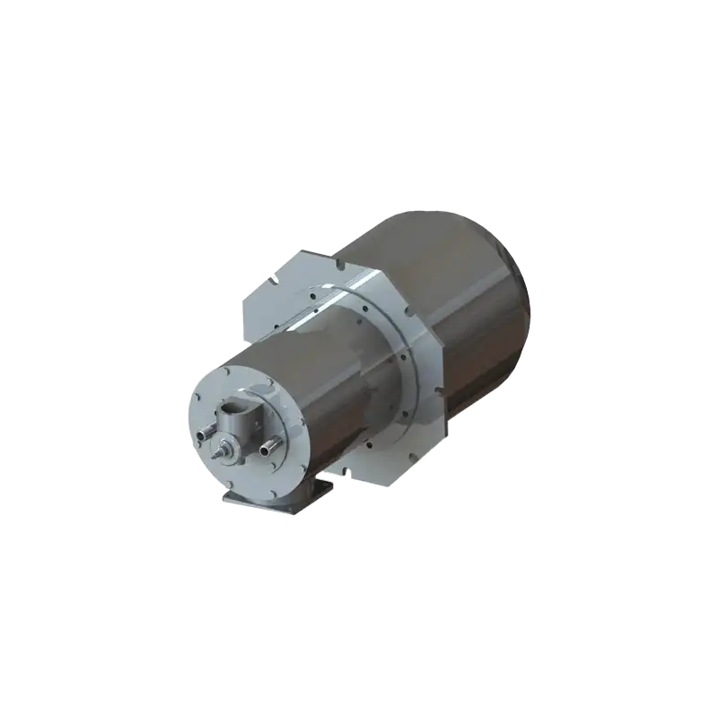
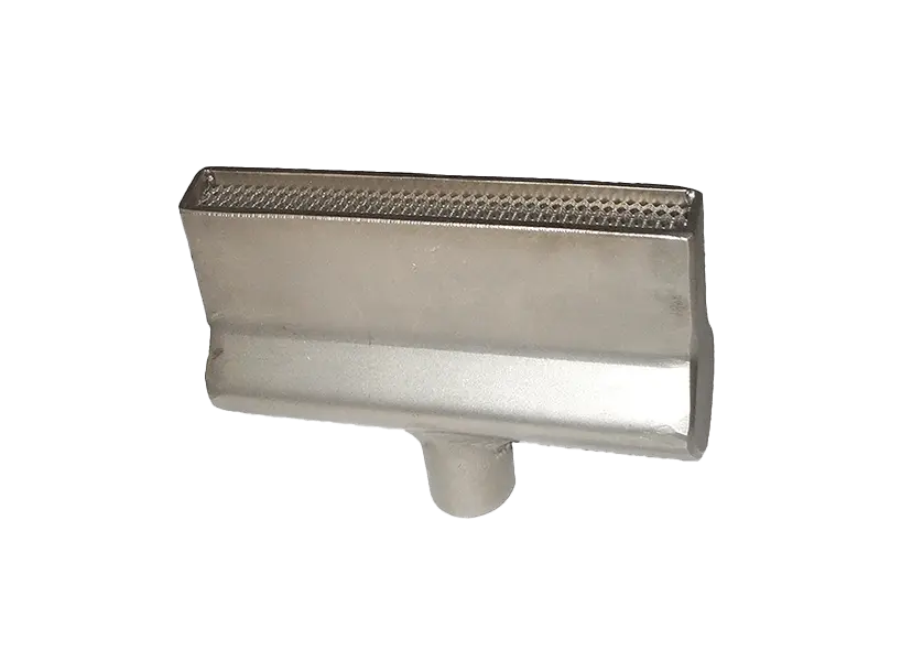
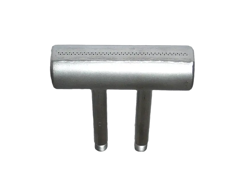
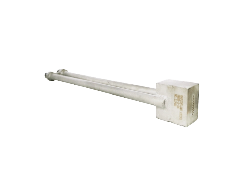
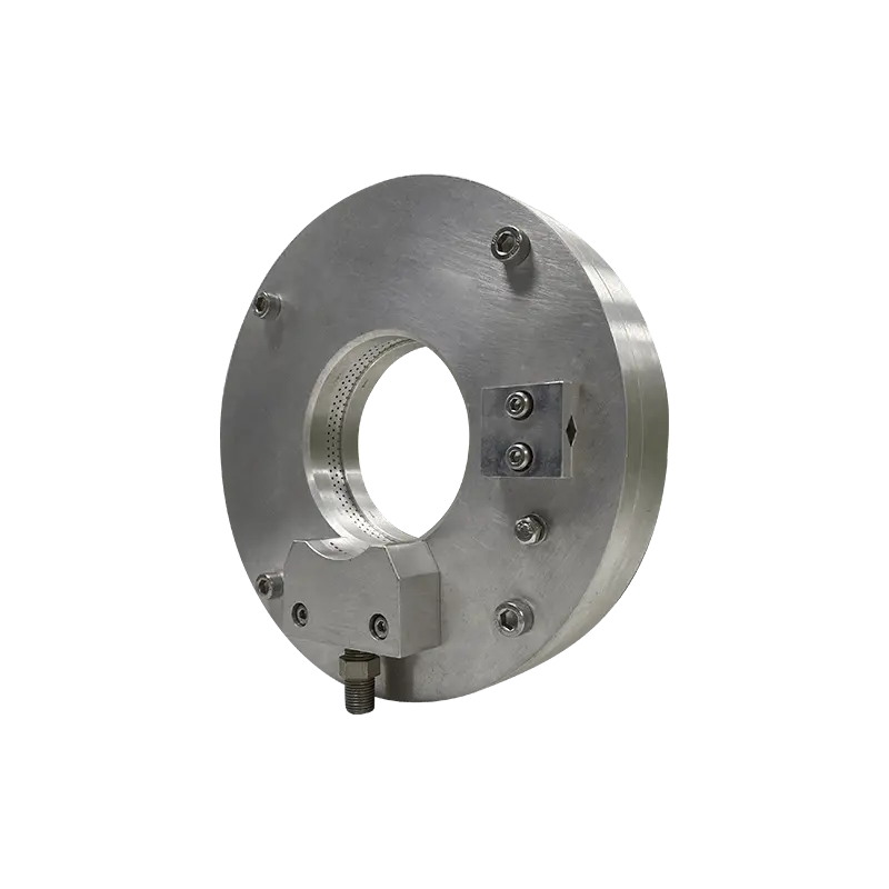
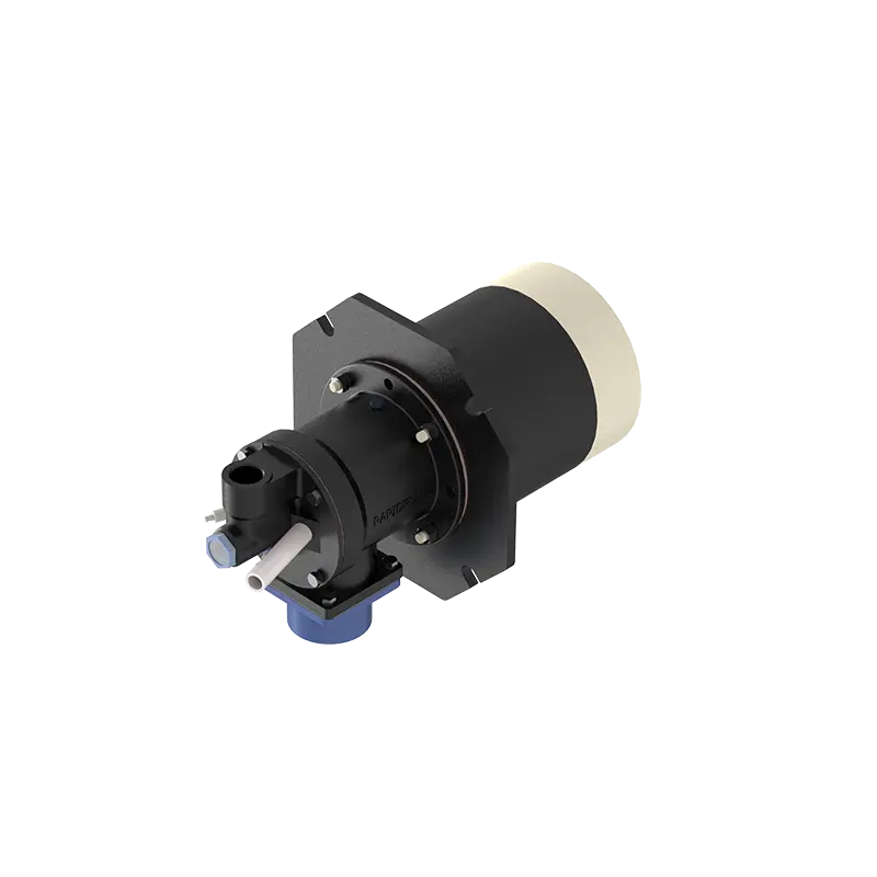
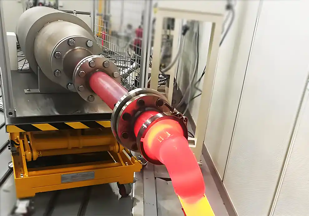
Burners are a core component of many gas-fired forging furnaces. Their primary function is to provide the controlled thermal energy required to heat metal billets, bars, slabs, or other workpieces to the temperature needed for forging.
However, a forging furnace does not simply need to become “hot enough.” The heating process must also achieve an appropriate temperature distribution, heating rate, residence time, and surface condition without creating excessive oxidation, scale formation, or localized overheating.
A typical thermal process can be represented as:
Cold Workpiece
↓
Preheating
↓
Heating
↓
Soaking / Temperature Equalization
↓
Forging
The burner system directly influences how heat is introduced into the furnace and how evenly that heat reaches the workpiece.
For this reason, burner selection for forging furnaces should consider:
Furnace heat load
Workpiece dimensions
Required heating temperature
Heating rate
Temperature uniformity
Flame length
Flame shape
Burner arrangement
Furnace pressure
Combustion air
Exhaust conditions
Burner turndown
Control requirements
A forging furnace is an industrial heating furnace used to heat metal to a suitable temperature before mechanical forming.
The furnace may be used for:
Billet heating
Bar heating
Slab heating
Preheating
Reheating
Die forging
Open-die forging
Other hot-forming processes
The required furnace temperature depends on the material and forging process.
The objective is to bring the workpiece into an appropriate temperature range while maintaining sufficient temperature uniformity for subsequent forming.
The burner converts fuel into controlled thermal energy.
The basic combustion process is:
Fuel + Combustion Air
↓
Ignition
↓
Stable Flame
↓
Hot Combustion Gases
↓
Heat Transfer to Workpiece
The burner determines not only how much heat is released, but also where and how that heat is released.
This is why burner capacity alone is not enough to evaluate a forging-furnace combustion system.
A forging furnace typically needs to heat metal rapidly enough to support production while maintaining an appropriate temperature distribution.
Poor burner selection can create:
Localized overheating
Cold zones
Uneven billet temperature
Excessive scale formation
Poor temperature control
Higher fuel consumption
Reduced production stability
A well-designed burner system should provide the required thermal input while creating a suitable temperature field throughout the furnace.
Burners are commonly arranged around the heating chamber or along different furnace zones.
The exact arrangement depends on:
Furnace dimensions
Workpiece size
Material loading
Heating rate
Required temperature
Production capacity
Furnace type
A multi-zone furnace may use separate burner groups for different sections.
For example:
Preheating Zone → Heating Zone → Soaking Zone
Each zone can have different thermal requirements.
Different sections of a forging furnace may perform different thermal functions.
The workpiece temperature is gradually increased.
The main heat input is provided.
The workpiece temperature is equalized before forging.
Using separate burner zones allows the furnace to control the thermal profile more precisely.
This is often more effective than using one large heat source for the entire furnace.
Burner arrangement determines where heat enters the furnace.
Poor arrangement can create:
Hot Areas + Cold Areas
This may result in uneven workpiece temperatures.
A suitable burner arrangement can improve:
Temperature uniformity
Heat transfer
Furnace response
Fuel utilization
Process stability
The number and location of burners should therefore be determined together with the furnace geometry.
Burner angle determines the direction in which the flame and combustion gases initially travel.
It can influence:
Flame trajectory
Gas circulation
Heat distribution
Flame interaction with the workpiece
Refractory temperature
Exhaust flow
The correct angle depends on the furnace structure.
The goal is generally to create an effective thermal field rather than simply point the flame directly at the workpiece.
This depends on the furnace design and combustion strategy.
Direct flame interaction may provide strong heat transfer, but uncontrolled flame impingement can create localized overheating.
Potential problems include:
Surface temperature peaks
Uneven heating
Excessive oxidation
Local scale formation
The flame should therefore be developed and positioned according to the workpiece dimensions and furnace geometry.
Flame length is particularly important in long forging furnaces.
If the flame is too short, heat release may be concentrated close to the burner.
If the flame is too long, it may:
Reach furnace walls
Impinge on workpieces
Interact with neighboring flames
Create excessive heat in downstream areas
The appropriate flame length depends on:
Furnace dimensions
Burner capacity
Burner spacing
Fuel type
Combustion-air conditions
Flame shape determines how thermal energy is distributed around the burner.
Possible flame characteristics include:
Long flame
Short flame
Broad flame
Narrow flame
High-momentum flame
Distributed heat-release pattern
For forging furnaces, the appropriate flame should provide sufficient heat transfer without creating unnecessary localized temperature peaks.
Furnace geometry strongly affects burner performance.
Important parameters include:
Furnace length
Furnace width
Furnace height
Burner elevation
Workpiece position
Burner spacing
Exhaust location
A burner configuration suitable for a long continuous forging furnace may not be appropriate for a compact batch furnace.
Burner selection should therefore be based on the actual furnace geometry.
Workpiece dimensions directly influence heat-transfer requirements.
Important factors include:
Billet diameter
Bar diameter
Slab thickness
Workpiece length
Material mass
Initial temperature
Large workpieces require more energy to reach the required forging temperature and may require more time for the center to reach the target temperature.
This means burner selection should consider not only furnace air temperature but also workpiece heating requirements.
The surface of a workpiece can heat much faster than its center.
If the furnace temperature is too high or heating is too aggressive, the surface may reach a high temperature while the core remains significantly cooler.
This can create undesirable thermal gradients.
A suitable burner system should therefore help establish an appropriate heating profile rather than simply maximize the furnace temperature.
Forging production often requires relatively rapid heating.
A higher production rate can increase the required thermal input.
However:
Higher Burner Capacity ≠ Automatically Faster Heating
Actual heating performance also depends on:
Heat-transfer efficiency
Furnace geometry
Workpiece arrangement
Burner location
Flame characteristics
Furnace insulation
Exhaust losses
The combustion system should therefore be designed around the complete thermal process.
Production rate is one of the key variables in burner sizing.
Higher throughput generally means more metal must be heated per unit of time.
Therefore:
Higher Throughput → Higher Required Heat Input
But the required burner capacity should also include:
Furnace heat losses
Exhaust losses
Door-opening losses
Startup requirements
Other process-related losses
A cold billet requires substantially more thermal energy than a preheated billet.
The burner system should therefore consider:
Initial workpiece temperature
Charging frequency
Material mass
Target temperature
Required heating time
A furnace operating with preheated material may have very different thermal requirements from one receiving cold material continuously.
Furnace pressure affects the movement of gases through the furnace.
Excessive negative pressure can draw unwanted air into the furnace through:
Doors
Seals
Charging openings
Other leakage points
Air infiltration can increase:
Oxygen availability
Exhaust losses
Fuel consumption
Temperature fluctuations
Maintaining appropriate furnace pressure is therefore an important part of combustion control.
Combustion air is necessary for stable combustion, but excessive air can reduce thermal efficiency.
The additional air must be heated before leaving through the exhaust system.
Excessive air can therefore increase:
Exhaust gas volume
Exhaust heat loss
Fuel consumption
Oxygen availability
However, insufficient air can lead to incomplete combustion and unstable flames.
The objective is an appropriate air-to-fuel ratio rather than simply minimizing air.
The exhaust system determines how combustion gases leave the furnace.
If exhaust flow is too high, useful thermal energy can be removed too quickly.
If exhaust flow is too low, combustion gases may not circulate through the furnace properly.
The burner and exhaust system should therefore be considered together.
Forging furnaces do not always operate at maximum thermal load.
Heat demand can change during:
Startup
Heating
Production
Reduced production
Holding
Shutdown
A burner with suitable turndown capability can reduce heat output while maintaining stable combustion.
This is particularly important for maintaining temperature near the target setpoint.
An oversized burner can provide sufficient maximum heat input but may be difficult to control at low load.
Potential problems include:
Temperature overshoot
Excessive burner cycling
Local overheating
Poor low-load stability
Increased fuel consumption
The burner should therefore be selected according to the entire operating range.
An undersized burner may not provide sufficient heat for the required production rate.
Potential consequences include:
Slow heating
Reduced throughput
Difficulty reaching target temperature
Longer heating cycles
Poor temperature recovery after charging
Burner capacity should therefore be based on the actual thermal load.
Scale formation is influenced by several factors, including:
Material temperature
Heating time
Furnace atmosphere
Oxygen availability
Combustion conditions
The burner itself does not independently determine scale formation.
However, appropriate combustion control can help manage the furnace thermal and atmospheric conditions.
For applications where oxidation and scale are particularly important, the combustion system should be designed together with the required furnace atmosphere and operating strategy.
A typical control loop can be represented as:
Temperature Measurement
↓
Controller
↓
Fuel / Air Adjustment
↓
Burner Output
↓
Furnace Temperature
Depending on the furnace, control may include:
Fuel modulation
Combustion-air control
Burner staging
Zone control
Temperature feedback
Flame detection
Safety interlocks
Multi-zone furnaces can use separate temperature-control loops for different heating zones.
Flame detection confirms that combustion has been successfully established and maintained.
A typical burner safety sequence may include:
Pre-purge
Ignition
Flame detection
Main fuel release
Stable combustion
Continuous monitoring
If flame failure occurs, the safety system should respond according to the designed protection logic.
Improving fuel efficiency requires more than selecting a high-efficiency burner.
A system-level approach should consider:
Avoid unnecessary oversizing.
Distribute heat according to furnace geometry.
Avoid heating unnecessary combustion air.
Reduce unwanted air infiltration.
Prevent excessive heat from leaving through the exhaust.
Reduce heat loss through furnace walls and openings.
Maintain stable operation at lower thermal loads.
Maximum capacity does not guarantee suitable operating performance.
Large billets and smaller billets can have very different heating requirements.
Flame development must match furnace dimensions.
Poor burner distribution can create hot and cold zones.
Air infiltration can disturb combustion and increase heat loss.
Too much air can increase exhaust losses.
The burner must remain stable when the furnace approaches the target temperature.
Burner, fuel, air, exhaust, refractory, and controls should be designed as one system.
A practical selection process can follow these steps.
Determine:
Material
Forging temperature
Production rate
Heating cycle
Required heating time
Determine:
Dimensions
Weight
Initial temperature
Material characteristics
Charging arrangement
Consider:
Workpiece heating
Furnace heat loss
Exhaust loss
Opening losses
Startup requirements
Determine:
Furnace dimensions
Burner locations
Workpiece position
Burner spacing
Exhaust location
Evaluate:
Burner capacity
Turndown ratio
Flame length
Flame shape
Flame momentum
Fuel requirements
Determine:
Burner quantity
Burner position
Burner angle
Heating zones
Burner elevation
Coordinate:
Fuel supply
Combustion air
Furnace pressure
Exhaust flow
Coordinate:
Temperature sensors
Fuel modulation
Air control
Burner staging
Flame detection
Safety interlocks
DYDTEC Combustion develops industrial burners and combustion-system solutions for industrial heating applications, including processes where controlled heat input and temperature distribution are important.
The company has developed 100+ burner models covering 200+ application scenarios. This allows burner configurations to be evaluated according to different furnace geometries, thermal loads, fuels, and operating requirements.
For forging furnaces, burner-system design can be considered around:
Burner capacity
Flame length
Flame shape
Flame momentum
Burner arrangement
Burner angle
Furnace geometry
Workpiece dimensions
Combustion air
Furnace pressure
Exhaust conditions
Temperature distribution
Turndown requirements
Control strategy
DYDTEC Combustion was established in 2012 and has R&D and manufacturing bases in Shanghai and Yangzhou.
The company has also developed 50+ patents and software copyrights, supporting its ongoing development of industrial combustion products and systems.
Burner selection can influence the design of the entire furnace.
It may affect:
Burner openings
Burner spacing
Furnace geometry
Refractory structure
Fuel piping
Combustion-air piping
Exhaust arrangement
Temperature zones
Control architecture
If the burner is selected only after the furnace has been designed, the OEM may have fewer options for optimizing the combustion system.
Early coordination allows:
Furnace Geometry + Burner + Fuel + Air + Exhaust + Control
to be considered as an integrated thermal system.
This is particularly important for high-throughput forging furnaces and furnaces requiring controlled temperature profiles.
Before selecting burners, an OEM should ideally provide:
Furnace type
Furnace length
Furnace width
Furnace height
Refractory structure
Burner installation locations
Exhaust location
Material
Dimensions
Weight
Initial temperature
Required forging temperature
Charging arrangement
Production rate
Heating cycle
Required heating time
Operating schedule
Fuel type
Fuel pressure
Fuel availability
Combustion-air pressure
Combustion-air temperature
Exhaust conditions
Desired furnace pressure
This information provides the foundation for determining burner capacity, flame characteristics, burner arrangement, and control strategy.
A burner provides controlled thermal energy to heat metal workpieces to the temperature required for forging.
The workpiece needs to reach an appropriate temperature throughout its relevant volume. Excessive temperature differences can affect the subsequent forging process.
Burners may be installed along the side walls, above or below the workpiece, or in different zones depending on furnace geometry.
Burner angle affects flame trajectory, gas circulation, heat distribution, and the interaction between the flame and furnace structure.
Flame length determines where the primary heat-release region develops and should be matched to the furnace dimensions and burner arrangement.
Yes. Workpiece mass and dimensions directly influence the required heat input and heating characteristics.
The furnace may experience poor low-load control, temperature overshoot, local overheating, and increased fuel consumption.
The furnace may not achieve the required heating rate or production capacity.
It allows stable operation across different thermal loads, especially when the furnace approaches the target temperature.
Yes. Excessive combustion air can increase exhaust volume and thermal losses.
Yes. Excessive negative pressure can draw unwanted air into the furnace and alter combustion and heat-transfer conditions.
Yes. Natural gas burners can be used when the burner and complete combustion system are designed for the required fuel and furnace conditions.
Ideally, yes. Early burner selection allows the furnace geometry, burner arrangement, fuel system, combustion air, exhaust, and control system to be designed together.
Burners in forging furnaces are more than simple heat sources.
They determine how thermal energy is released, distributed, and transferred to the metal workpiece.
A successful forging-furnace combustion system needs to coordinate:
Burner Capacity
Flame Characteristics
Burner Arrangement
Furnace Geometry
Workpiece Dimensions
Combustion Air
Furnace Pressure
Exhaust
Temperature Control
The objective is not simply to produce a high furnace temperature. It is to heat the workpiece at the required rate, to the required temperature, with an appropriate temperature distribution and stable process control.
For forging-furnace OEMs, burner selection should therefore be considered during the early stage of furnace design.
The right forging-furnace burner is not simply the burner with sufficient capacity. It is the combustion system that matches the furnace geometry, workpiece load, heating cycle, flame characteristics, airflow, and control requirements to deliver the required heat efficiently and consistently.