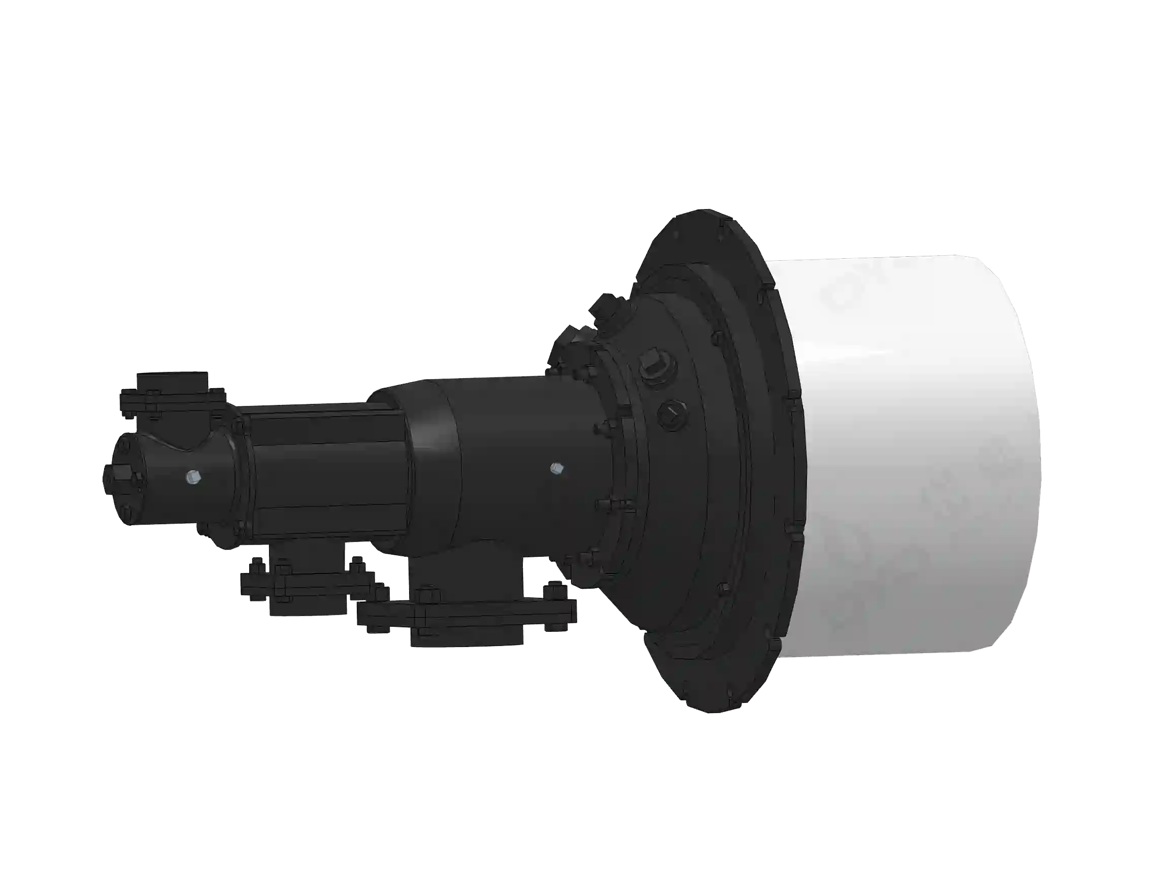
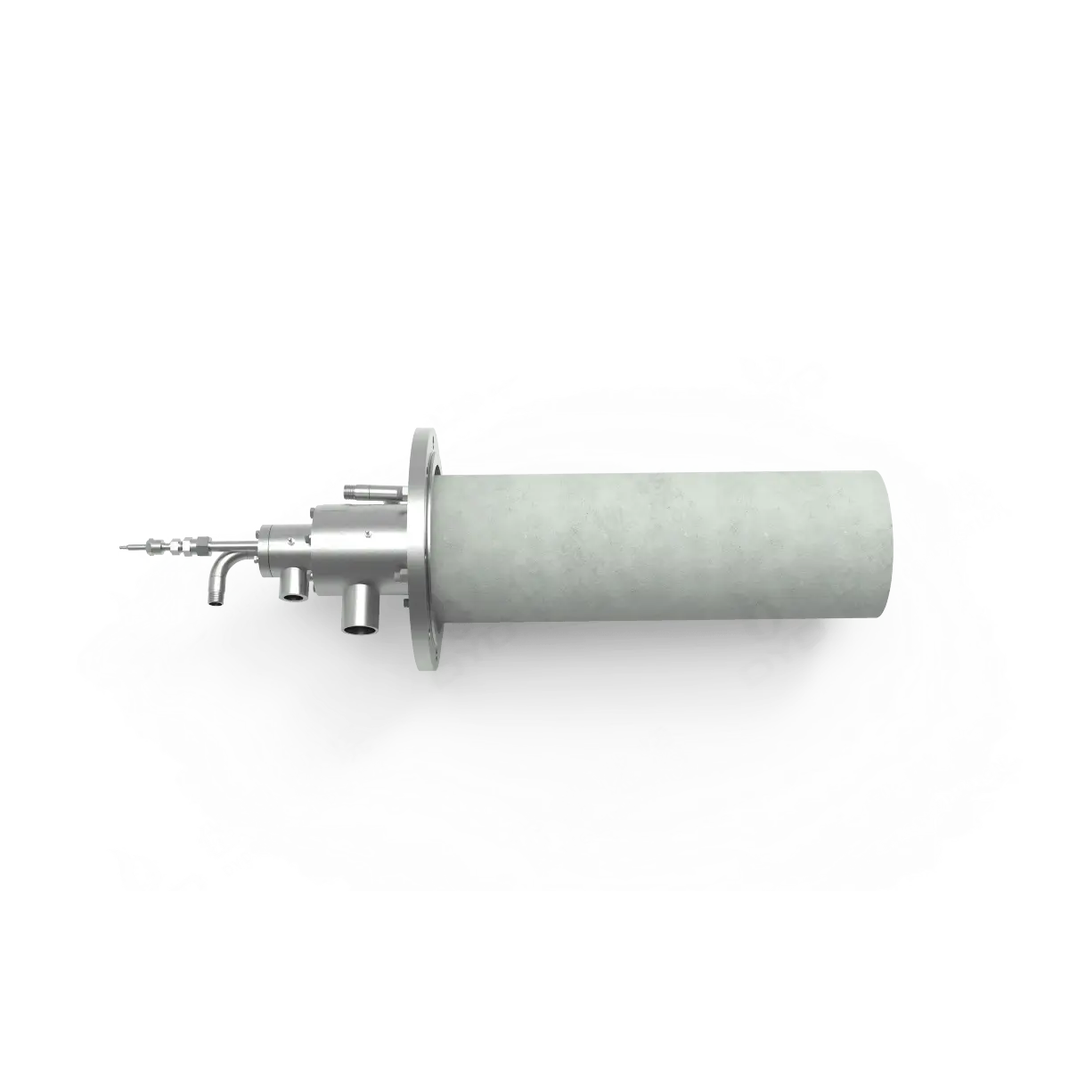
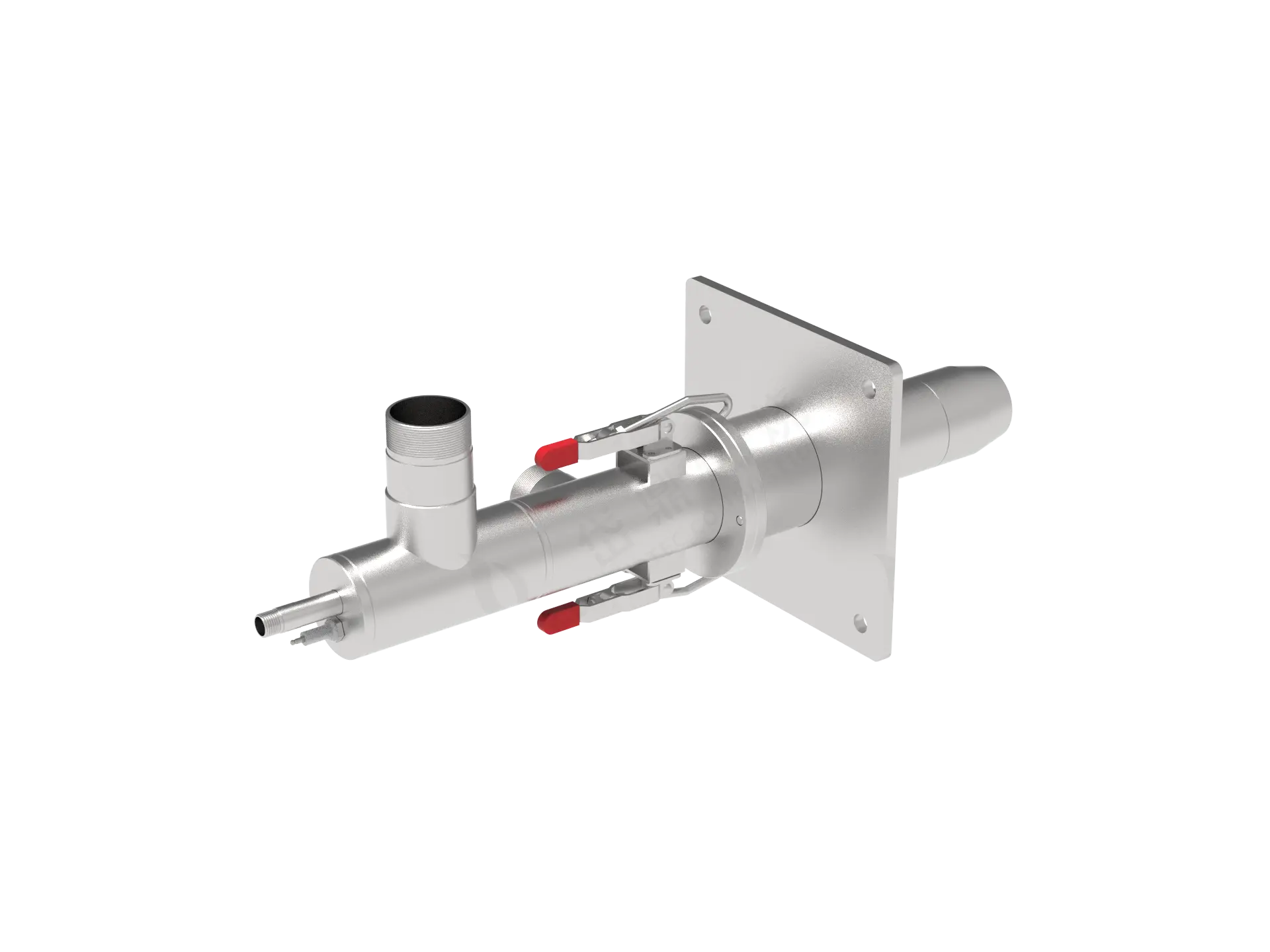
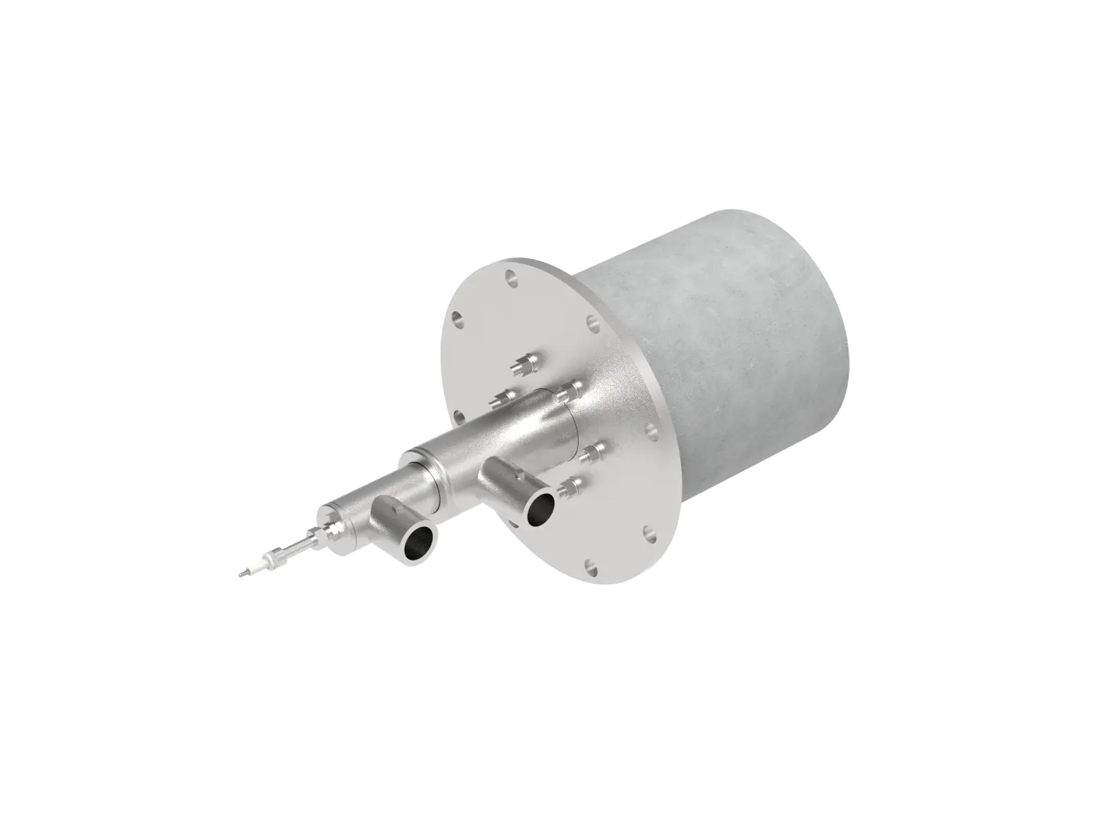
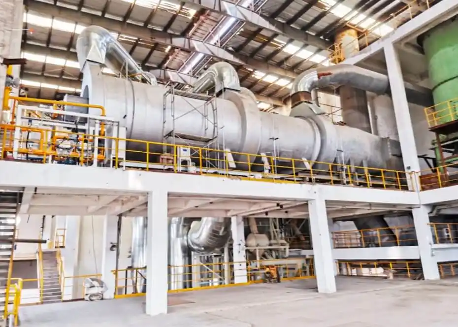
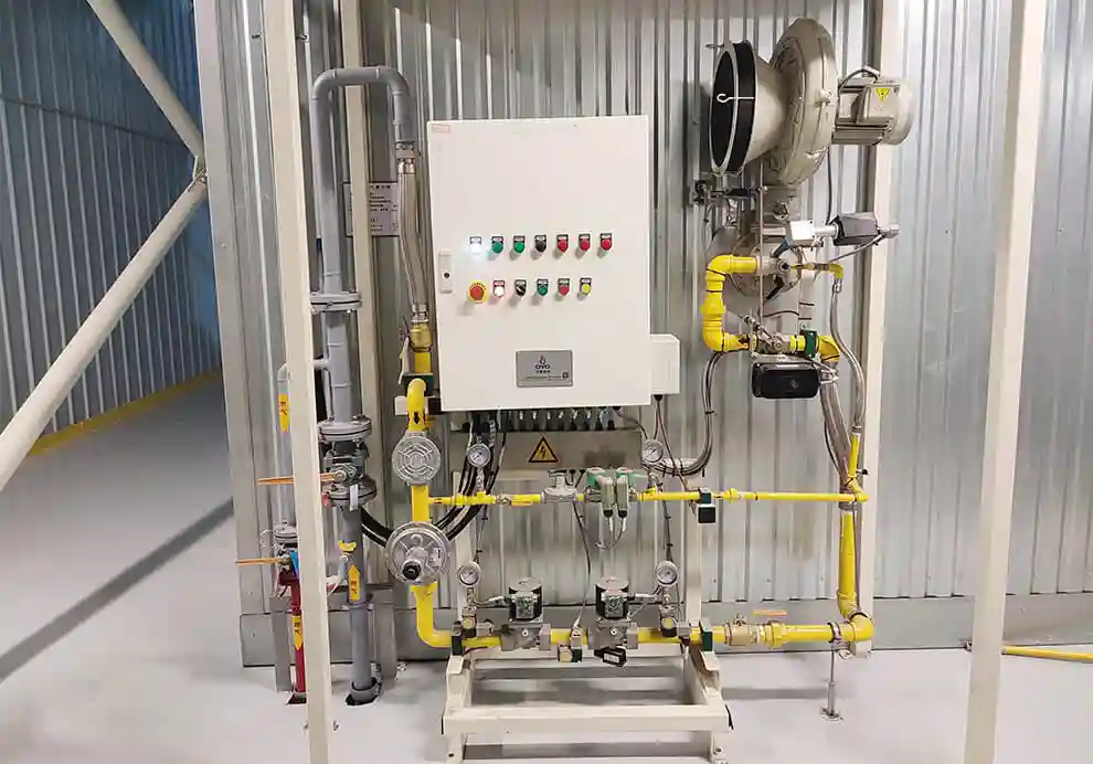
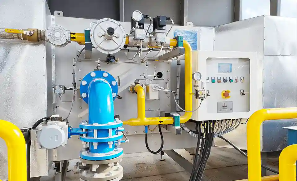
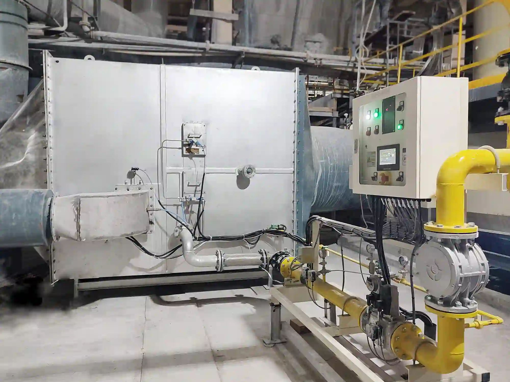
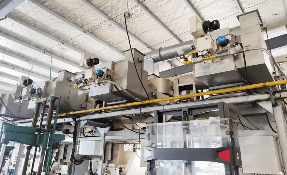
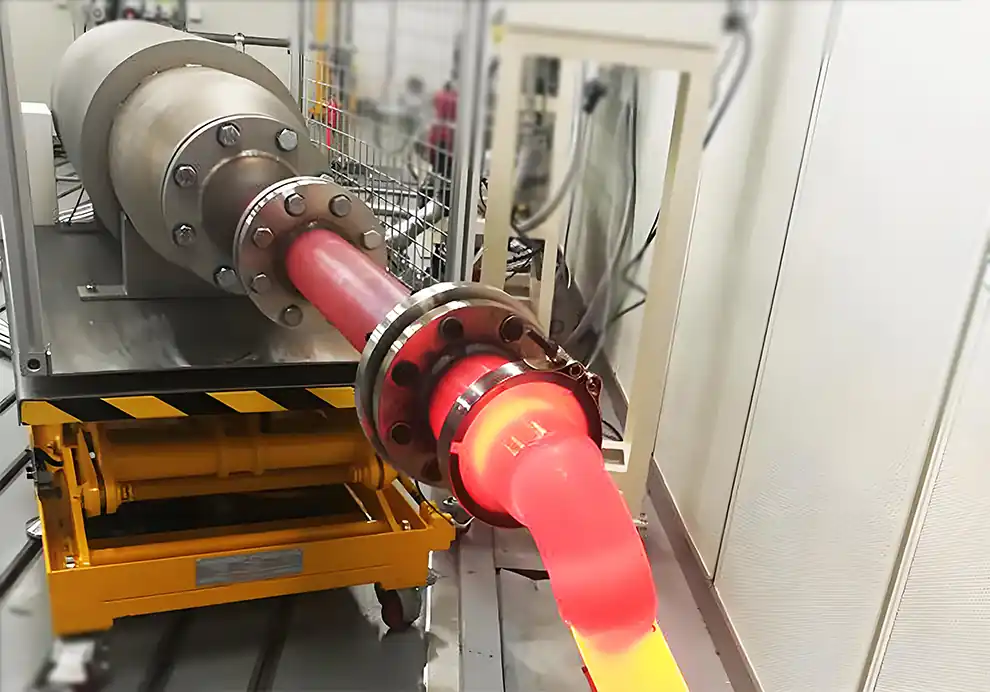
Burners are an important part of many gas-fired heat treatment furnaces. Their role is not simply to generate heat, but to provide stable, controllable, and uniform thermal energy throughout the heat treatment cycle.
Unlike a simple heating chamber, a heat treatment furnace must often follow a defined temperature-time profile. The workpiece may need to be heated gradually, held at a specific temperature, and then cooled according to a controlled process.
A simplified process can be represented as:
Loading → Heating → Soaking → Controlled Cooling → Unloading
The burner system directly affects the heating stage and, depending on the furnace design, can also influence the atmosphere and gas circulation throughout the furnace.
For this reason, burner selection should consider:
Furnace heat load
Furnace geometry
Heating rate
Temperature uniformity
Flame characteristics
Combustion air
Furnace atmosphere
Furnace pressure
Burner turndown
Temperature control
Exhaust conditions
The objective is to heat the workpiece to the required temperature uniformly and controllably, rather than simply reaching a high furnace temperature.
A heat treatment furnace is industrial equipment used to heat materials or components according to a controlled thermal cycle.
Depending on the process, heat treatment may include:
Annealing
Normalizing
Hardening
Tempering
Stress relieving
Solution treatment
Preheating
Other controlled thermal processes
Different processes require different temperature profiles.
For example, one process may require gradual heating followed by a long soaking period, while another may require rapid heating followed by controlled cooling.
The combustion system must therefore be matched to the specific thermal process.
The primary function of the burner is to convert fuel into controlled thermal energy.
The basic process is:
Fuel + Combustion Air
↓
Ignition
↓
Stable Flame
↓
Hot Combustion Gases
↓
Heat Transfer
↓
Workpiece
The burner determines how thermal energy is introduced into the furnace.
Important burner characteristics include:
Heat-release rate
Flame length
Flame shape
Flame momentum
Air-to-fuel ratio
Turndown capability
A well-designed burner system helps create a stable thermal environment around the workpiece.
Temperature uniformity is one of the most important requirements in many heat treatment processes.
The furnace temperature and the actual workpiece temperature are not necessarily identical.
Differences can occur because of:
Furnace geometry
Workpiece arrangement
Burner position
Air circulation
Furnace insulation
Heat transfer
Loading density
If one part of the workpiece reaches the target temperature while another remains significantly cooler, the final material properties may differ.
Uneven heating can contribute to:
Inconsistent hardness
Distortion
Residual stress
Uneven microstructure
Dimensional variation
Product rejection
Therefore, burner design must consider the entire furnace thermal field.
Burners can be installed in different configurations depending on furnace geometry.
Common arrangements include burners positioned:
Along side walls
Along both sides
Above the workpiece
Below the workpiece
At multiple elevations
In several independently controlled zones
The arrangement is determined by:
Furnace dimensions
Workpiece location
Required temperature uniformity
Heat load
Required heating rate
Internal circulation
The goal is to distribute thermal energy evenly rather than concentrate heat in one area.
Burner arrangement determines where heat is introduced into the furnace.
If burners are poorly positioned, the furnace may develop:
Hot Zones + Cold Zones
For example, a burner located too close to one section of the workpiece may create excessive local heating while another section receives insufficient heat.
A well-designed arrangement can distribute thermal energy across the furnace volume.
This is particularly important for large workpieces and furnaces with complex internal geometry.
Burner angle determines the initial direction of the flame and combustion gases.
It can influence:
Gas circulation
Heat distribution
Flame trajectory
Local heat intensity
Interaction with furnace walls
Workpiece heating
The correct angle depends on the furnace geometry.
A burner should not simply be pointed toward the workpiece. The flame and hot gases need to create an appropriate overall thermal field.
Direct flame contact should be evaluated carefully.
In some heating applications, direct flame exposure may be acceptable or intentionally used.
However, in many heat treatment processes, excessive direct flame impingement can produce localized overheating or unwanted surface effects.
Potential problems include:
Local temperature peaks
Uneven heating
Surface oxidation
Scaling
Thermal stress
The appropriate flame configuration therefore depends on the material, heat treatment process, furnace atmosphere, and burner design.
Flame length needs to match the furnace dimensions and burner arrangement.
If the flame is too long, it may:
Reach furnace walls
Impinge on the workpiece
Interact with neighboring flames
Create localized hot zones
If the flame is too short, heat release may become concentrated near the burner.
The appropriate flame length depends on:
Furnace width
Furnace height
Burner spacing
Burner capacity
Fuel type
Airflow
Flame shape determines how thermal energy is distributed around the burner.
Depending on the application, a burner may produce:
Long flames
Short flames
Broad flames
Narrow flames
High-momentum flames
More distributed heat-release patterns
For heat treatment, the objective is usually to create a suitable thermal field rather than maximize flame temperature at one point.
Furnace geometry has a direct influence on burner performance.
Important dimensions include:
Furnace length
Furnace width
Furnace height
Workpiece position
Burner location
Exhaust location
A burner that works well in a long, narrow furnace may not be appropriate for a wide chamber.
The burner should therefore be selected together with the furnace geometry.
The workpiece load determines how much useful heat the furnace must transfer.
Important variables include:
Workpiece mass
Material type
Initial temperature
Workpiece dimensions
Loading density
Production rate
A lightly loaded furnace and a heavily loaded furnace can have very different thermal requirements.
Burner capacity should therefore be based on realistic operating conditions.
Workpieces can block or redirect the movement of hot gases.
A dense load may restrict circulation and create temperature differences.
For this reason, burner arrangement should consider:
Workpiece spacing
Workpiece orientation
Loading height
Airflow paths
Available circulation space
The combustion system and loading pattern should work together to achieve uniform heating.
Different heat treatment processes require different heating rates.
A higher heating rate requires a higher effective heat-transfer rate.
However, increasing burner capacity is not always enough.
The furnace must also transfer heat effectively to the workpiece.
Therefore:
Burner Capacity + Gas Circulation + Furnace Geometry + Heat Transfer
all contribute to the actual heating rate.
An oversized burner may have enough capacity to heat the furnace quickly, but it can be difficult to control at lower output.
Potential problems include:
Temperature overshoot
Excessive cycling
Poor low-load stability
Local overheating
Higher fuel consumption
Burner selection should therefore consider both maximum and minimum operating conditions.
An undersized burner may not provide sufficient thermal input.
Possible consequences include:
Slow heating
Failure to reach the required temperature
Extended heating cycles
Reduced production capacity
Difficulty recovering temperature after loading
The burner should be selected according to the actual heat load and required production cycle.
Heat treatment furnaces operate at different thermal loads during the cycle.
For example:
Heating
→ High heat demand
Approaching Setpoint
→ Reduced heat demand
Soaking
→ Lower heat demand
A burner with an appropriate turndown ratio can reduce its output while maintaining stable combustion.
This can improve:
Temperature stability
Low-load operation
Fuel utilization
Control accuracy
A typical control relationship is:
Temperature Sensor
↓
Temperature Controller
↓
Fuel/Air Adjustment
↓
Burner Output
↓
Furnace Temperature
Depending on the system, control may include:
Modulating fuel valves
Combustion-air control
Burner staging
Zone control
Temperature feedback
Flame detection
Safety interlocks
Multi-zone furnaces may use independent control loops for different sections.
Large heat treatment furnaces often require multiple temperature zones.
Each zone can have its own burner or group of burners.
This allows the furnace to control:
Heating rate
Temperature distribution
Compensation for heat losses
Different thermal requirements along the furnace
A simplified system might look like:
Zone 1 → Zone 2 → Zone 3 → Zone 4
with each zone independently adjusted according to its temperature requirement.
Combustion air influences both combustion quality and furnace thermal conditions.
The air-to-fuel ratio affects:
Flame stability
Flame temperature
Exhaust volume
Oxygen availability
Heat loss
Too much air can increase exhaust losses.
Too little air can result in incomplete combustion and unstable flames.
The burner therefore needs an appropriate combustion-air supply throughout its operating range.
Excess combustion air must also be heated before it leaves the furnace.
This increases the amount of energy carried away by exhaust gases.
Excessive air can therefore increase:
Exhaust gas volume
Exhaust heat loss
Fuel consumption
However, reducing air excessively can compromise combustion.
The objective is to maintain an appropriate air-to-fuel ratio for stable and efficient operation.
Furnace pressure affects gas movement and air infiltration.
Excessive negative pressure can draw cold air into the furnace through:
Doors
Seals
Openings
Other leakage points
This can cause:
Temperature fluctuations
Increased oxygen availability
Additional heat loss
Changes in combustion behavior
Appropriate furnace pressure is therefore part of the overall thermal-system design.
The exhaust system controls the removal of combustion gases.
Excessive exhaust flow can remove useful heat too quickly.
Insufficient exhaust can result in:
Poor gas movement
Unstable furnace conditions
Inadequate removal of combustion products
The burner, combustion-air system, and exhaust system should therefore be designed together.
Some heat treatment processes require a controlled furnace atmosphere.
The combustion process can influence the atmosphere through:
Oxygen availability
Excess air
Combustion products
Furnace pressure
Gas circulation
Depending on the material and process, atmosphere control may be important for limiting:
Oxidation
Scaling
Surface reactions
Burner selection should therefore consider the required furnace atmosphere.
Yes, but the burner configuration may need to change according to the process.
Different processes can require different combinations of:
Temperature
Heating rate
Soaking time
Atmosphere
Temperature uniformity
For example, a burner system optimized for a rapid preheating application may not be ideal for a process requiring extremely uniform long-duration soaking.
The combustion system should be matched to the process rather than treated as a universal component.
A system-level approach is usually the most effective.
Avoid unnecessary oversizing.
Distribute thermal energy according to furnace geometry and workpiece loading.
Match flame length, shape, and momentum to the furnace.
Avoid excessive excess air.
Reduce unwanted cold-air infiltration.
Avoid removing excessive useful heat.
Maintain stable combustion during soaking and low-load operation.
Allow different furnace sections to respond independently to their thermal requirements.
A high-capacity burner may perform poorly at low output.
Flame development must fit the actual chamber.
Heat distribution depends on the location and arrangement of the load.
Long flames can create local overheating or flame impingement.
Flame direction influences gas circulation and temperature distribution.
Air infiltration can disturb thermal conditions.
Soaking conditions may require much less heat than initial heating.
Exhaust conditions directly influence furnace pressure and heat loss.
The actual workpiece arrangement can significantly affect circulation.
A practical selection process can follow these steps.
Determine:
Process type
Target temperature
Heating rate
Soaking temperature
Soaking time
Required cooling conditions
Determine:
Material
Mass
Dimensions
Initial temperature
Loading arrangement
Production rate
Consider:
Workpiece heating
Furnace heat loss
Exhaust losses
Door-opening losses
Startup requirements
Determine:
Furnace dimensions
Burner locations
Workpiece location
Exhaust locations
Internal circulation paths
Evaluate:
Burner capacity
Turndown
Flame length
Flame shape
Momentum
Fuel requirements
Determine:
Burner quantity
Position
Spacing
Angle
Elevation
Heating zones
Coordinate:
Fuel flow
Combustion air
Furnace pressure
Exhaust flow
Coordinate:
Temperature sensors
Fuel modulation
Air control
Burner staging
Flame detection
Safety interlocks
DYDTEC Combustion develops industrial burners and combustion-system solutions for industrial heating applications where temperature control, heat distribution, and combustion stability are important.
The company has developed 100+ burner models covering 200+ application scenarios, allowing burner configurations to be evaluated according to different furnace geometries, thermal loads, fuels, and process requirements.
For heat treatment furnaces, burner-system design can be considered around:
Burner capacity
Flame length
Flame shape
Flame momentum
Burner position
Burner angle
Furnace geometry
Workpiece loading
Combustion air
Furnace pressure
Exhaust conditions
Temperature uniformity
Turndown ratio
Multi-zone control
DYDTEC Combustion was established in 2012 and has R&D and manufacturing bases in Shanghai and Yangzhou.
The company serves 12,600+ customers, providing experience across different industrial heating applications and equipment configurations.
Burner selection can influence the design of the entire furnace.
It can affect:
Burner openings
Burner spacing
Furnace geometry
Refractory design
Air piping
Fuel piping
Exhaust arrangement
Temperature zones
Control architecture
If the burner is selected only after the furnace has been designed, opportunities to optimize the thermal system may be limited.
Early coordination allows:
Furnace Geometry + Burner + Fuel + Air + Exhaust + Control
to be considered as one integrated system.
This is particularly important when the furnace requires tight temperature uniformity or a specific heating curve.
Before selecting a burner, the OEM should ideally provide:
Furnace type
Furnace length
Furnace width
Furnace height
Refractory structure
Burner installation locations
Exhaust locations
Material
Dimensions
Weight
Initial temperature
Loading arrangement
Production rate
Target temperature
Heating rate
Soaking temperature
Soaking time
Atmosphere requirements
Temperature-uniformity requirements
Fuel type
Fuel pressure
Fuel availability
Combustion-air pressure
Combustion-air temperature
Exhaust conditions
Desired furnace pressure
This information provides the foundation for determining burner capacity, burner type, quantity, arrangement, and control strategy.
Burners provide controlled thermal energy for heating the workpiece according to the required heat treatment cycle.
Uneven workpiece temperatures can result in inconsistent material properties, dimensional variation, residual stress, or other quality problems.
Depending on furnace geometry, burners may be installed along the side walls, above or below the workpiece, or at multiple elevations and zones.
Yes. Burner angle affects flame trajectory, gas circulation, and heat distribution.
Yes. Flame length should be compatible with furnace dimensions, burner spacing, and workpiece position.
This depends on the specific process, but uncontrolled flame impingement can create local overheating and unwanted surface effects.
It allows the burner to operate stably at lower heat loads during temperature stabilization and soaking.
Oversized burners can cause temperature overshoot, poor low-load control, excessive cycling, and local overheating.
Undersized burners may not provide enough thermal input to achieve the required heating rate or production capacity.
No. Workpiece load, heating rate, process temperature, heat loss, exhaust conditions, and furnace geometry must also be considered.
Excessive air increases exhaust volume and can increase heat loss and oxygen availability.
Yes. Uncontrolled negative pressure can draw cold air into the furnace and disturb temperature and atmosphere conditions.
Yes. Natural gas burners can be used when the burner and complete combustion system are designed for the required furnace conditions.
Burner requirements should ideally be considered during the early furnace-design stage so that burner locations, flame characteristics, airflow, exhaust, and control zones can be coordinated.
Burners in heat treatment furnaces are not simply heat sources.
They are part of an integrated thermal system that determines how effectively and uniformly heat reaches the workpiece.
The key factors include:
Burner Capacity
Flame Characteristics
Burner Arrangement
Furnace Geometry
Workpiece Loading
Combustion Air
Furnace Pressure
Exhaust
Temperature Control
For heat treatment applications, the objective is not simply to reach the required furnace temperature. The real objective is to achieve the required workpiece temperature, heating rate, soaking conditions, temperature uniformity, and process stability.
For OEM furnace manufacturers, burner selection should therefore be considered during the early stage of furnace design.
Ultimately:
The right heat treatment furnace burner is not simply the burner with enough capacity to heat the chamber. It is the combustion system that delivers heat uniformly and controllably according to the furnace geometry, workpiece load, thermal cycle, and process requirements.