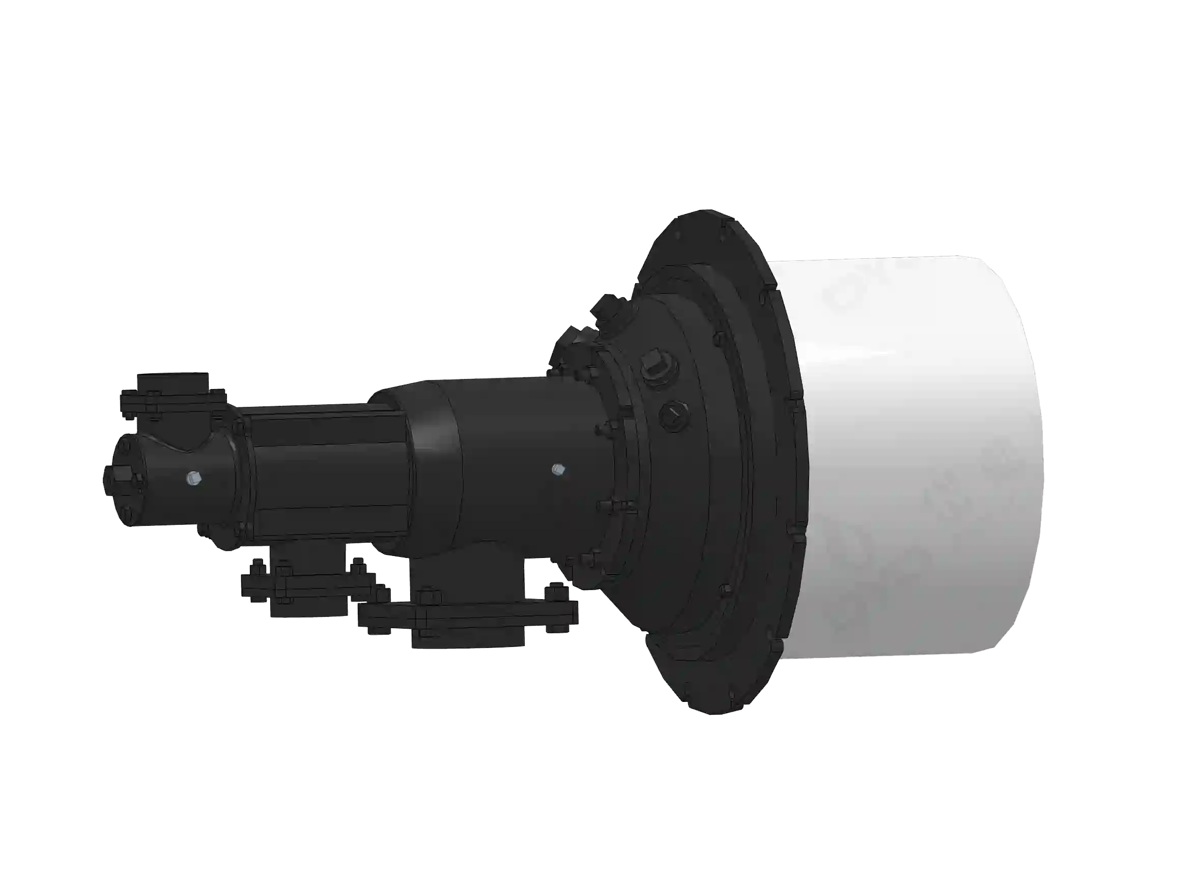
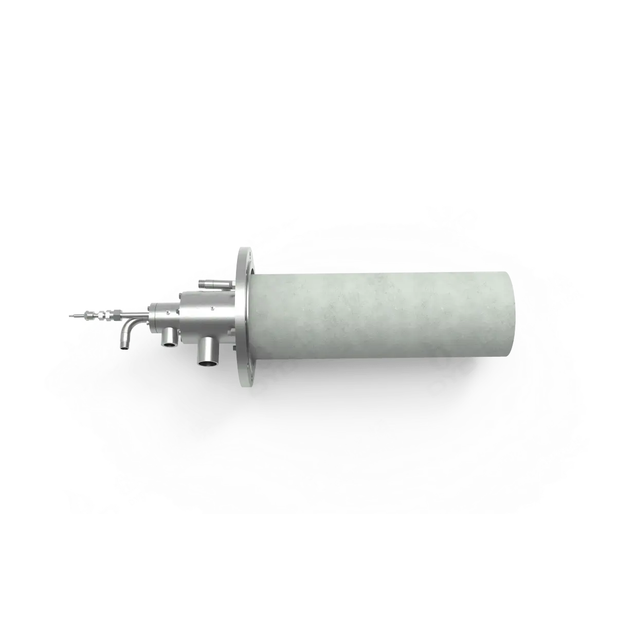
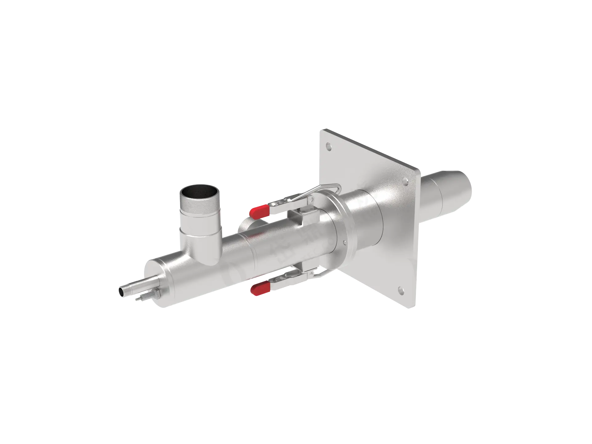
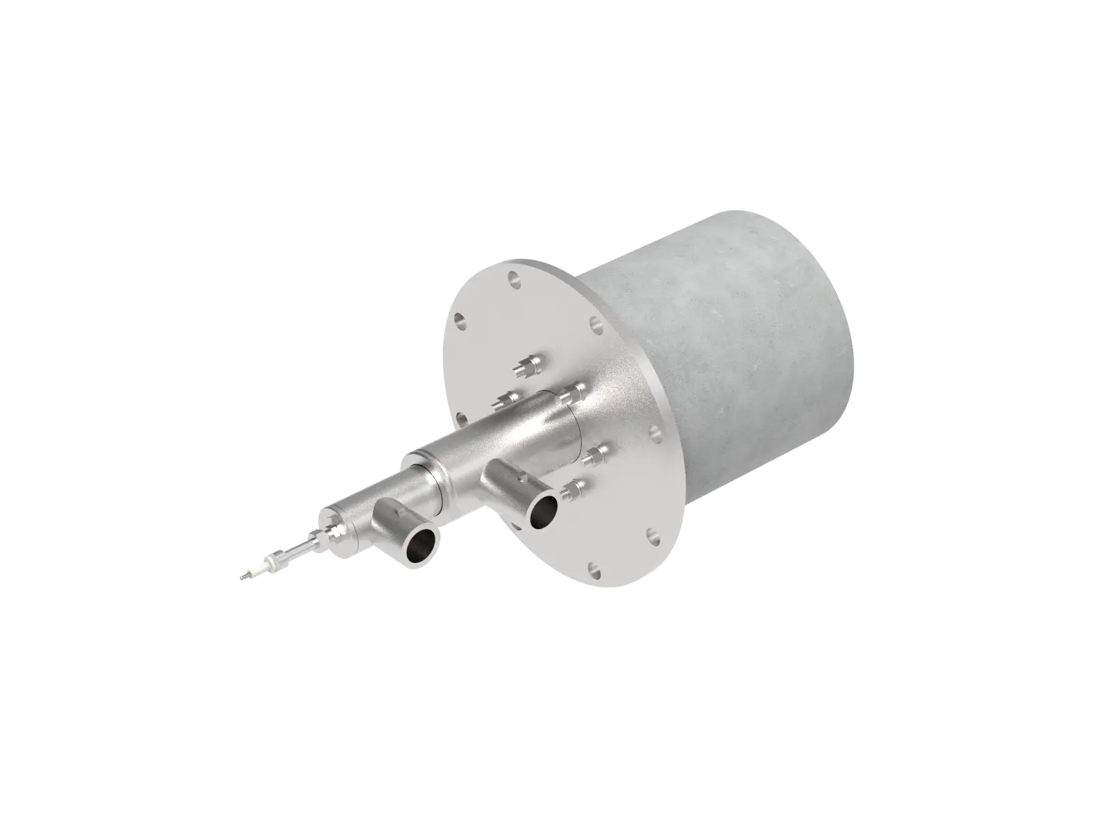
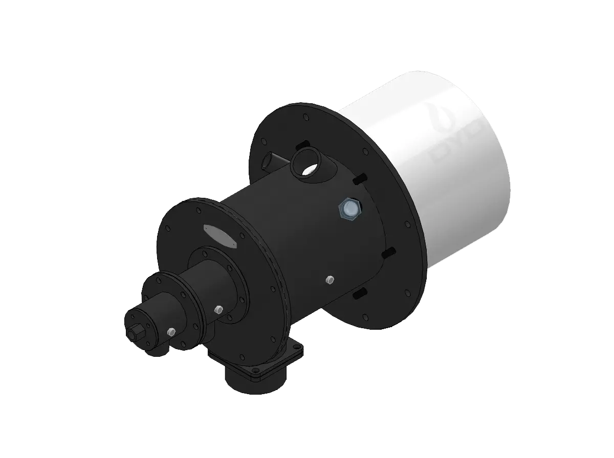
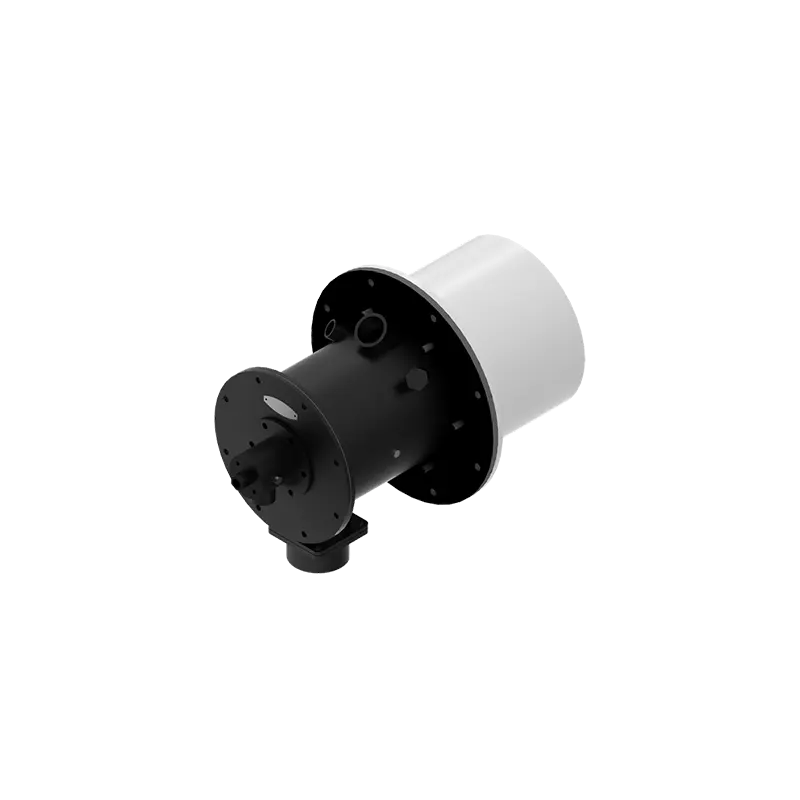
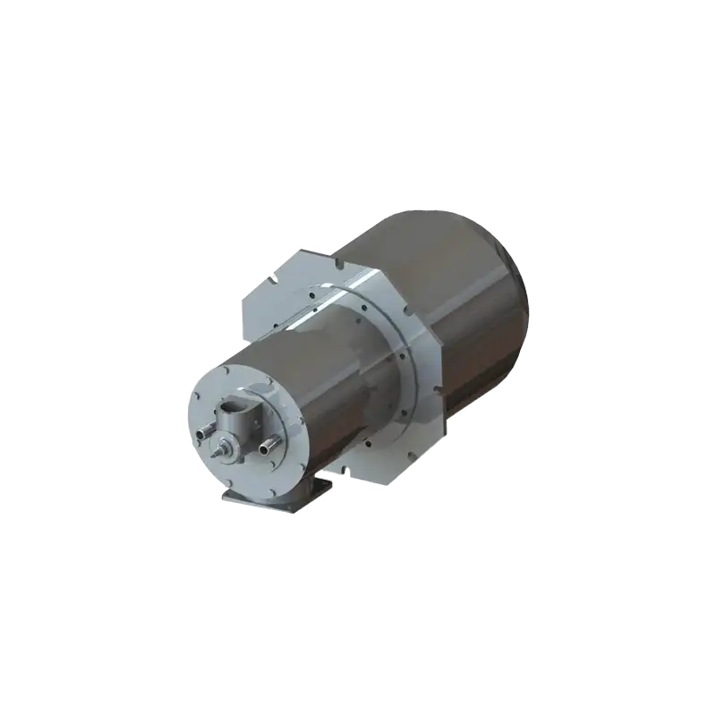
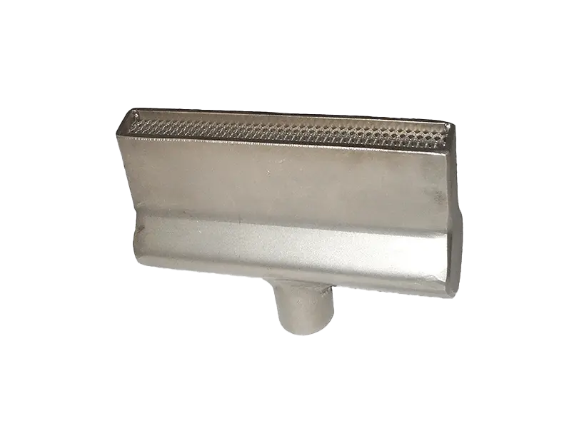
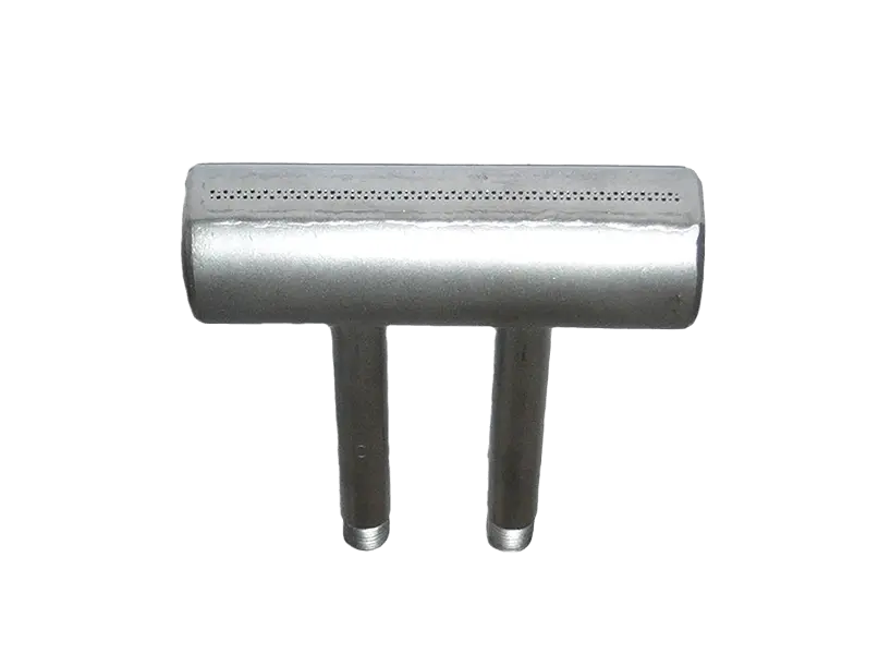
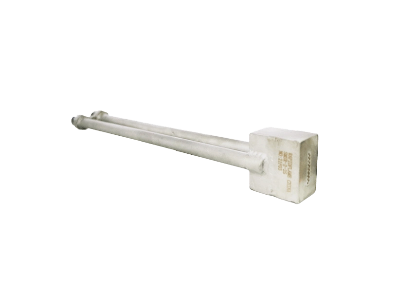
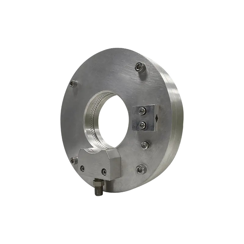
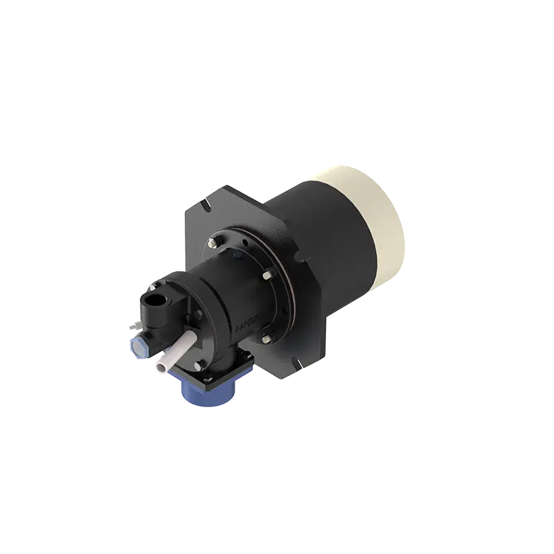
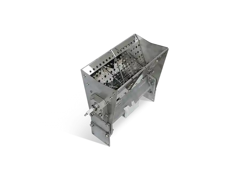
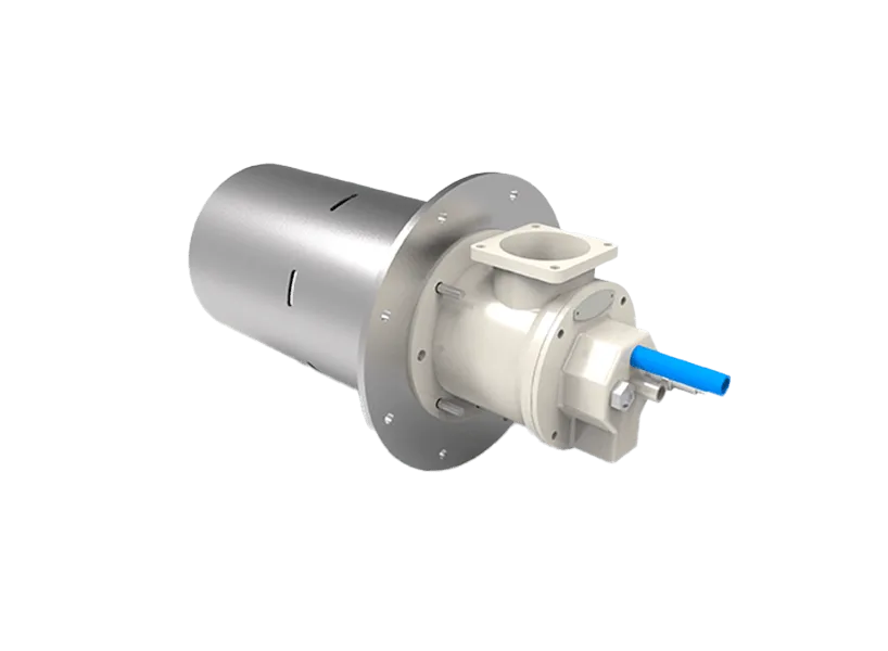
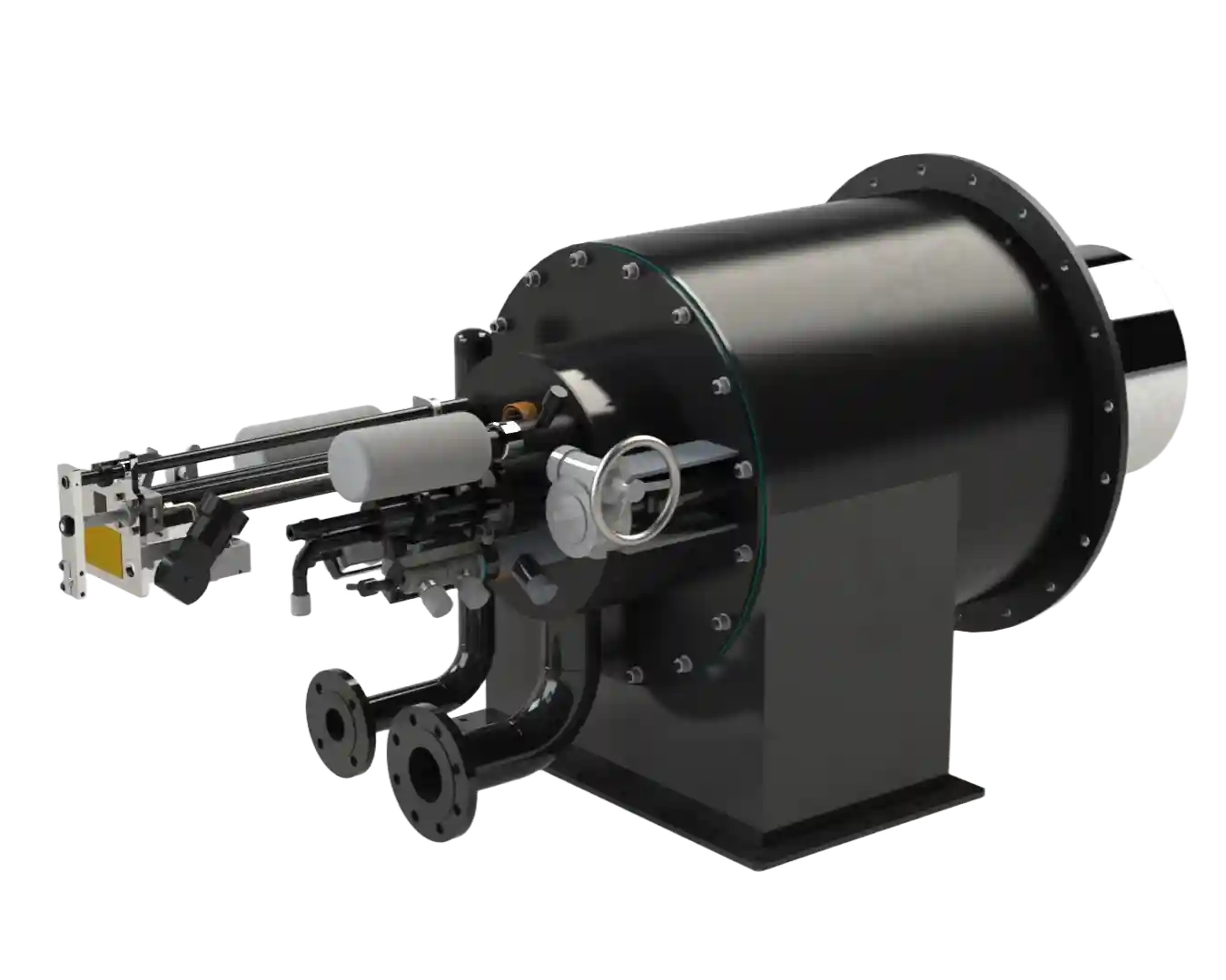
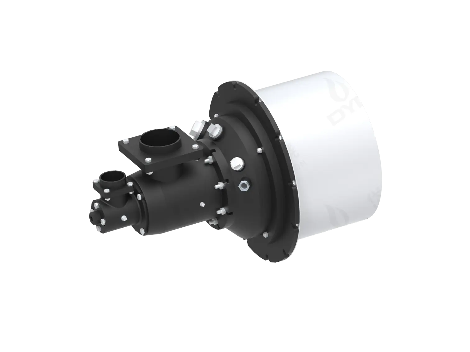
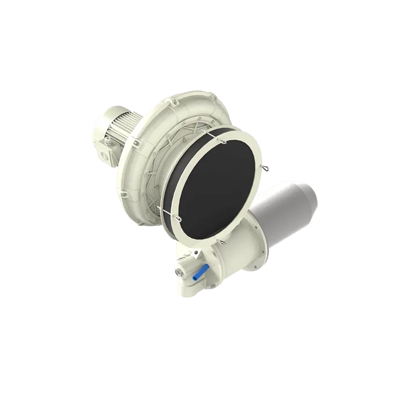
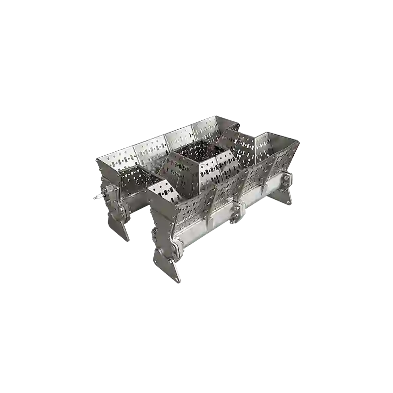
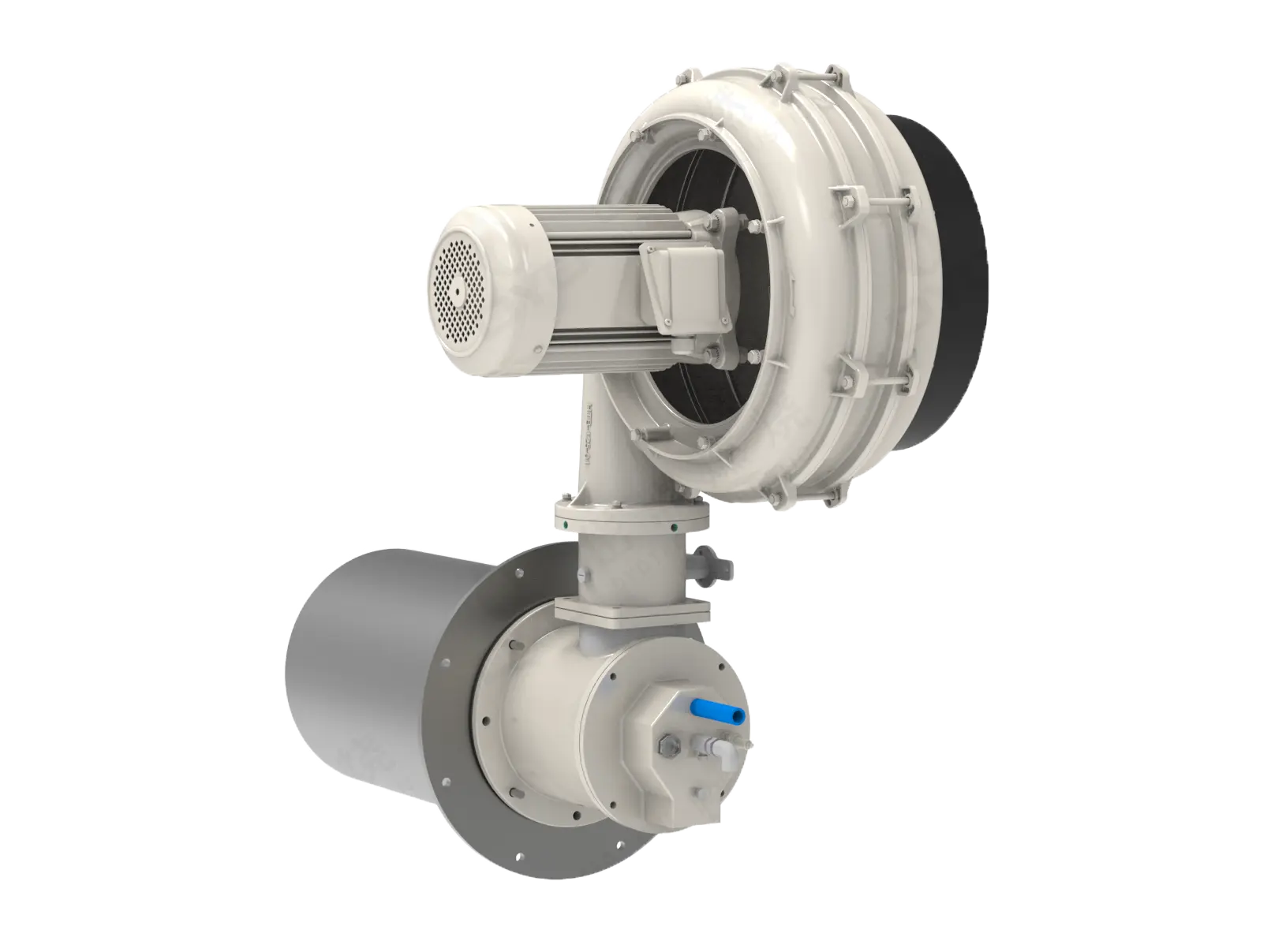
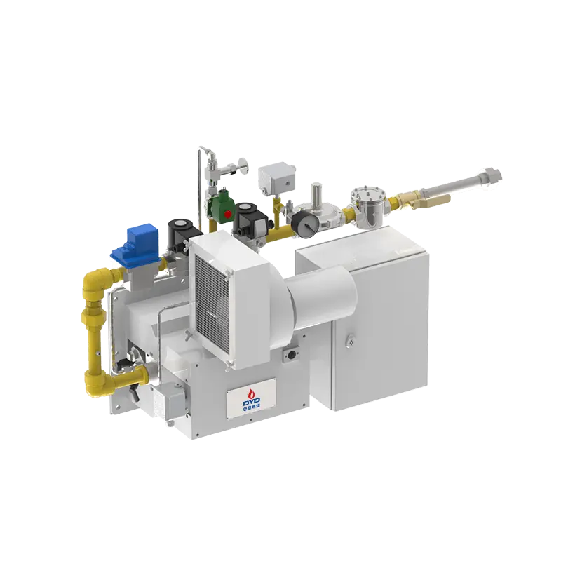
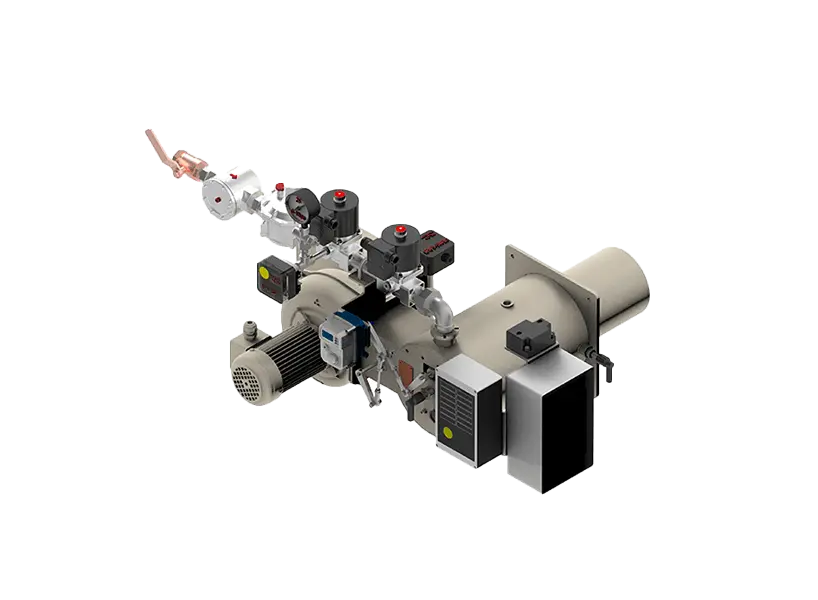
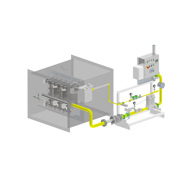
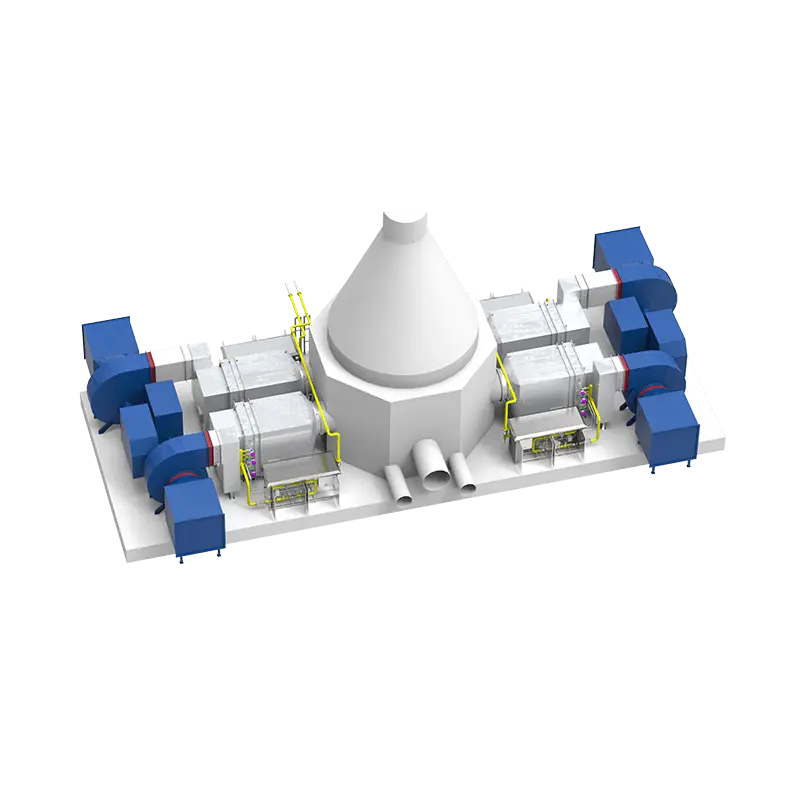
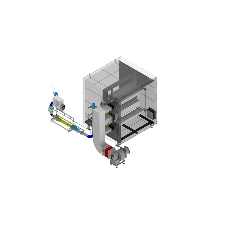
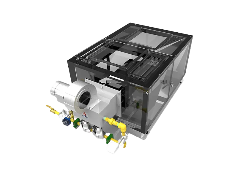
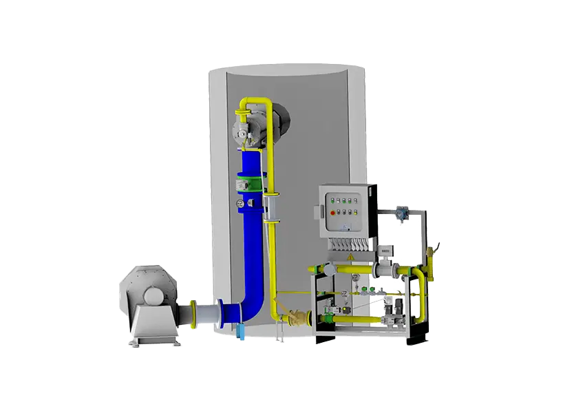
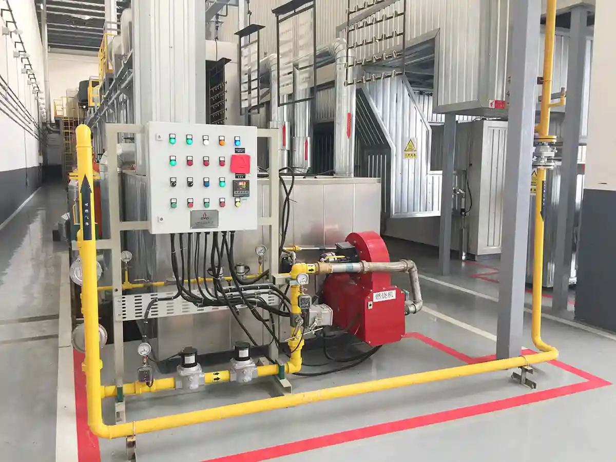
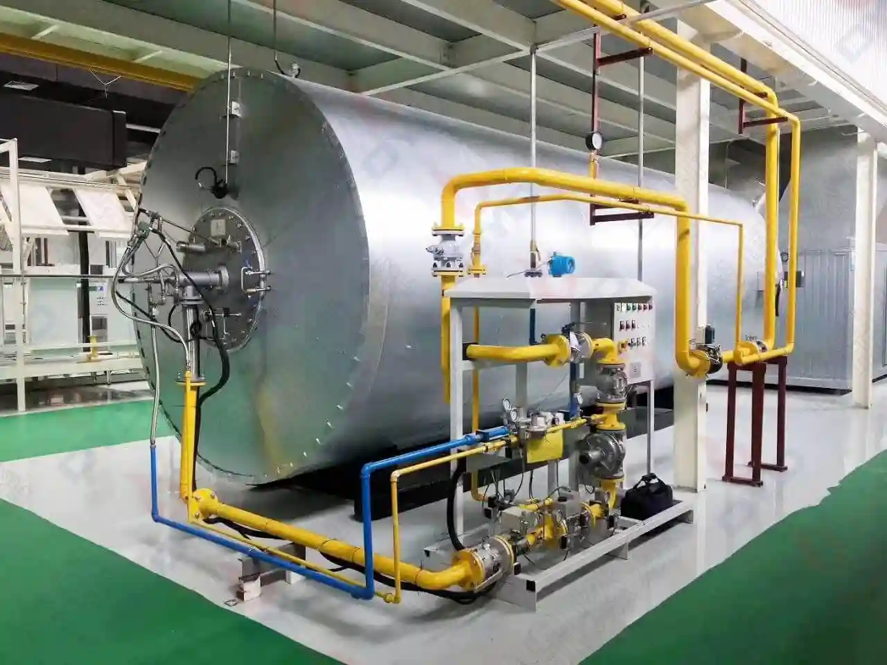
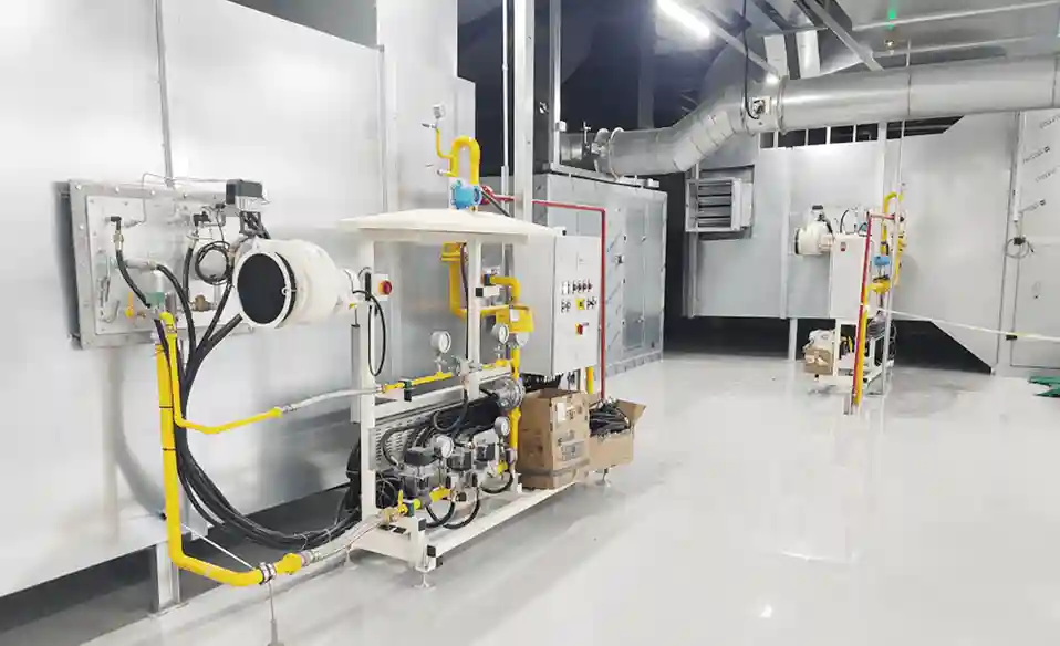
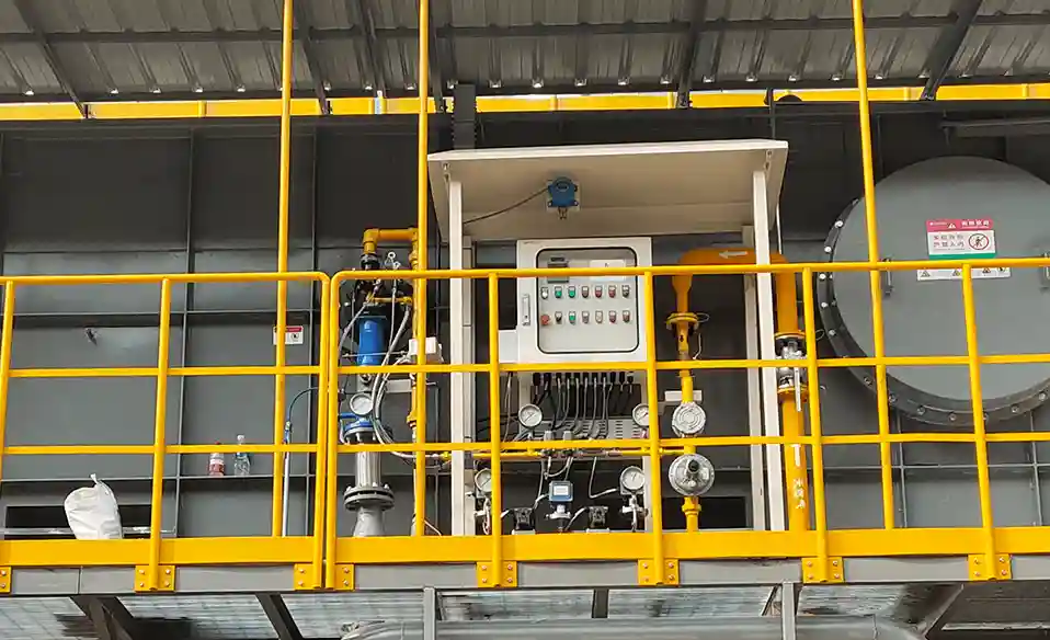
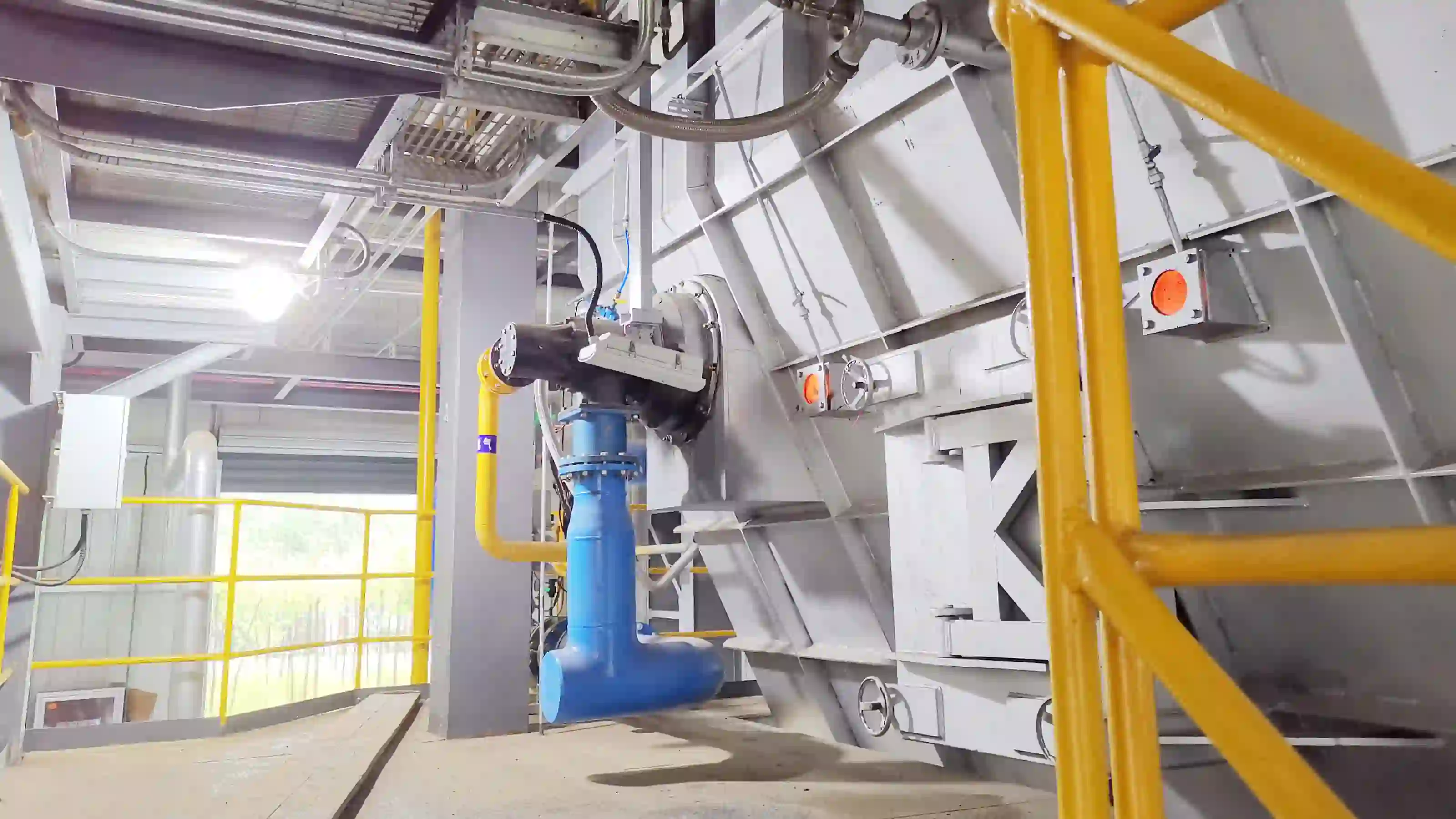
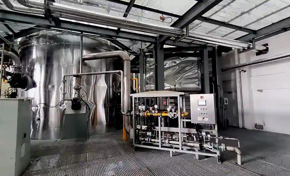
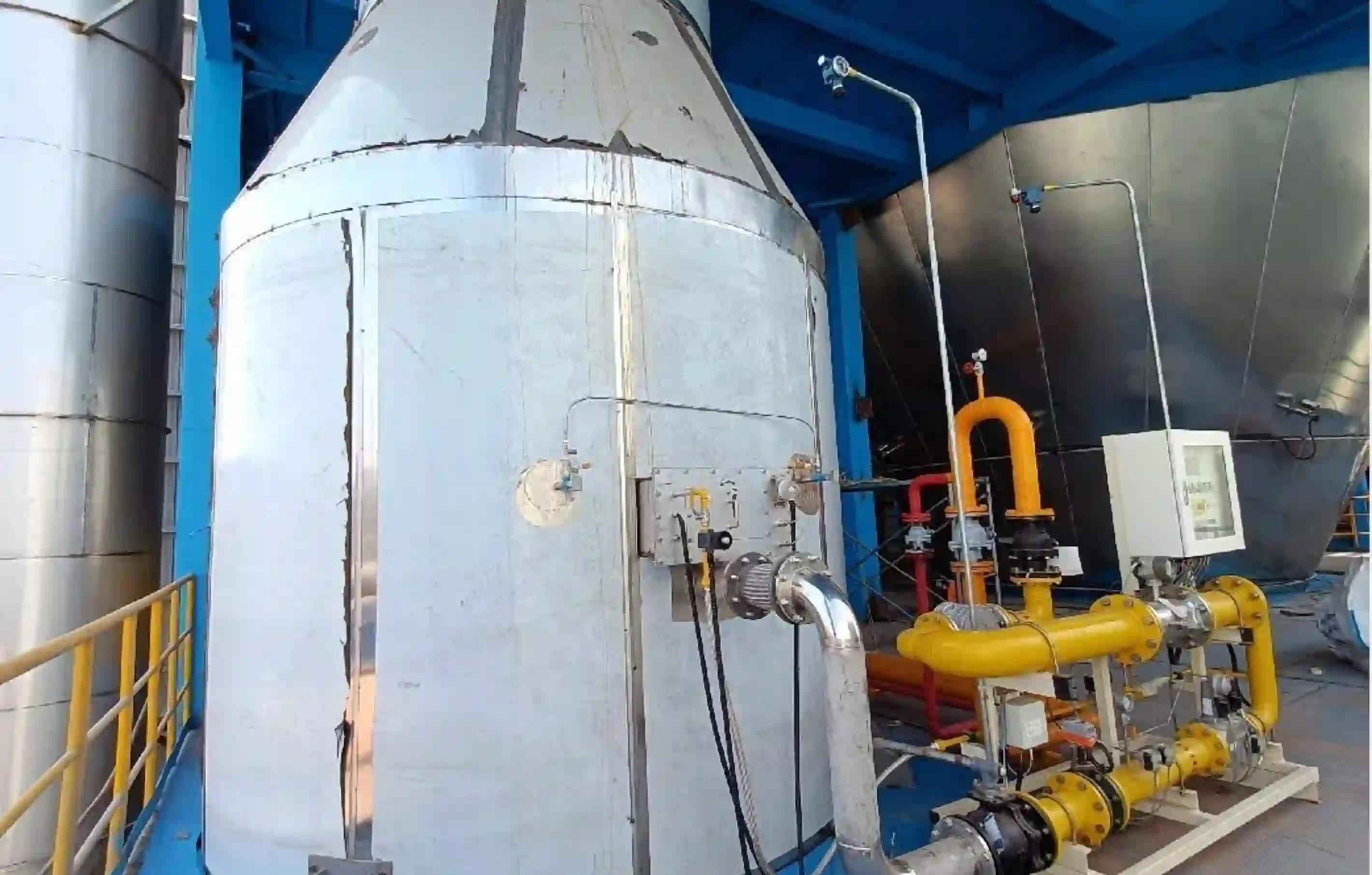
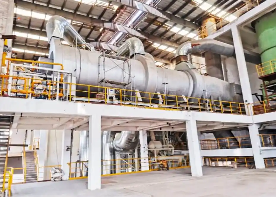
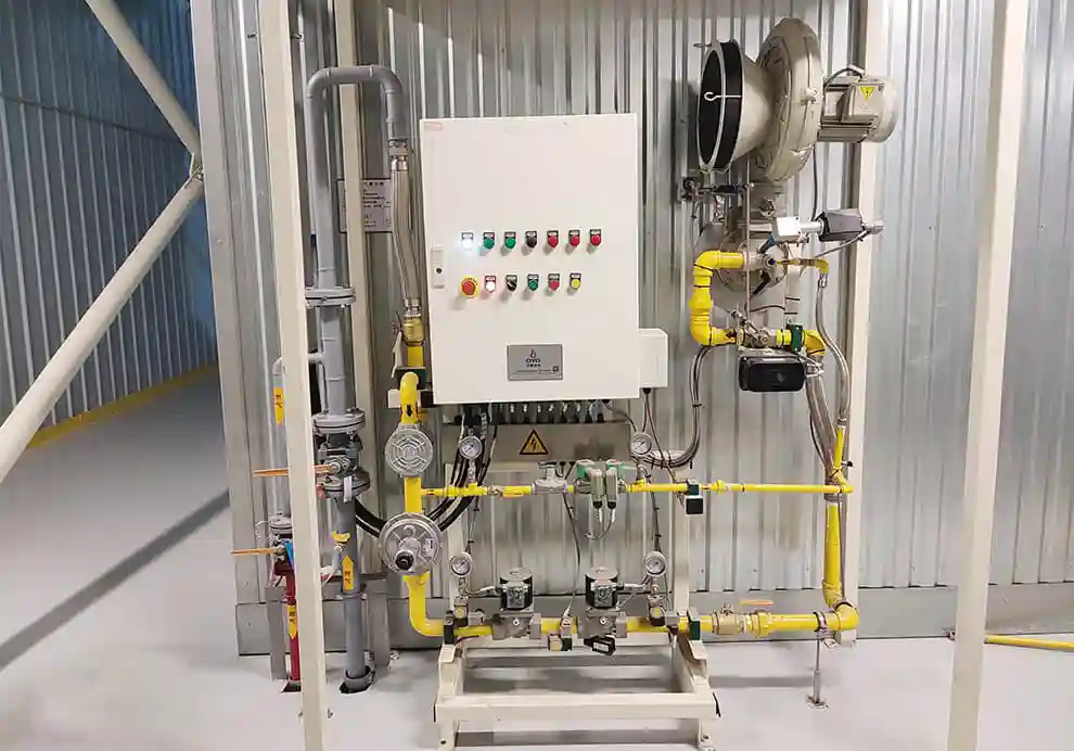
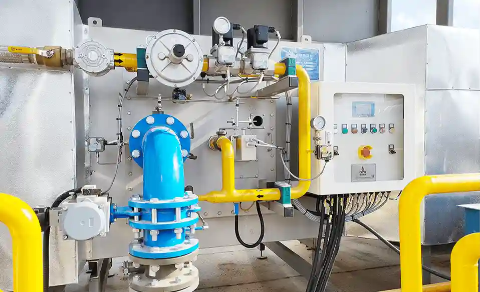
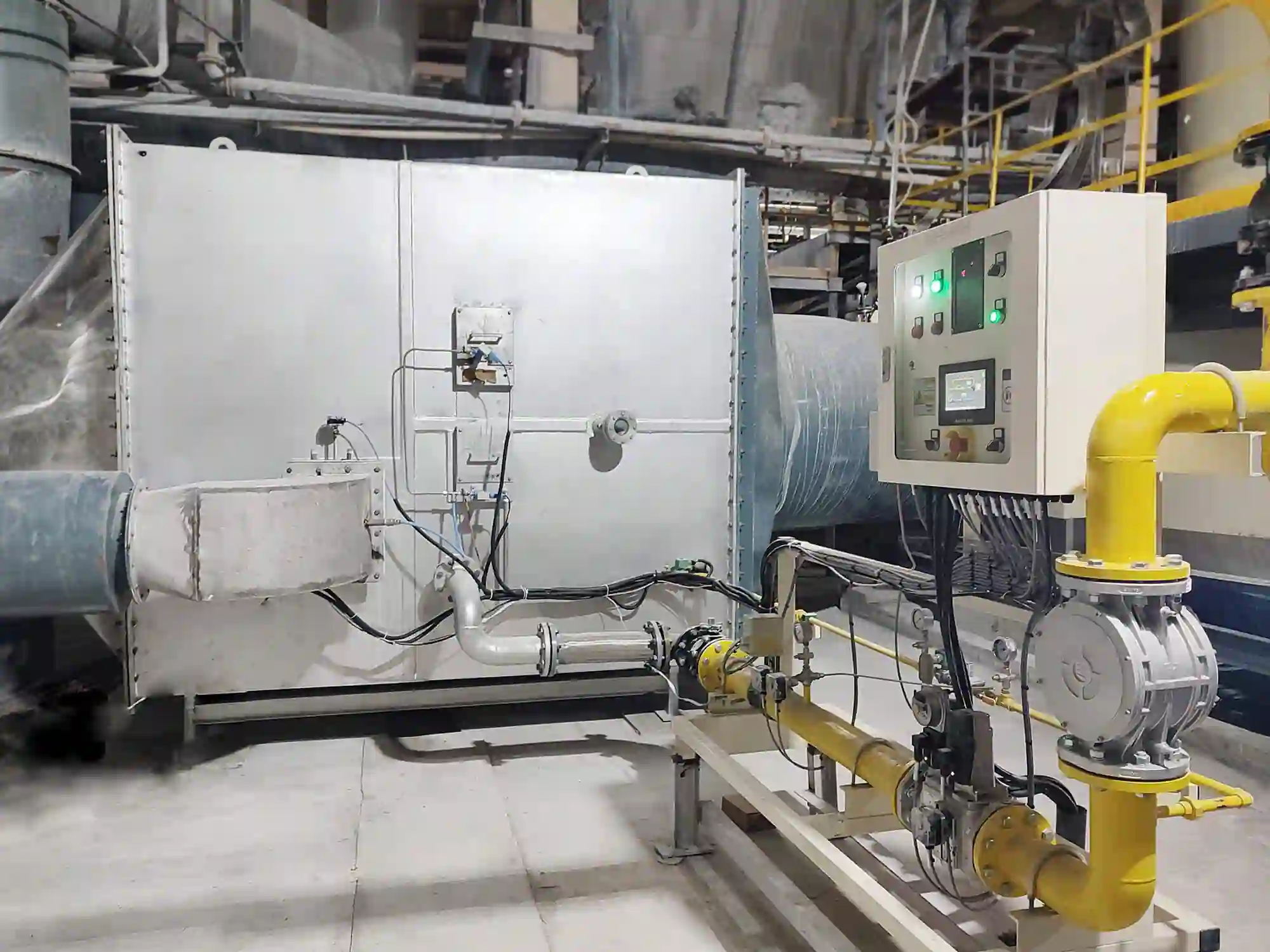
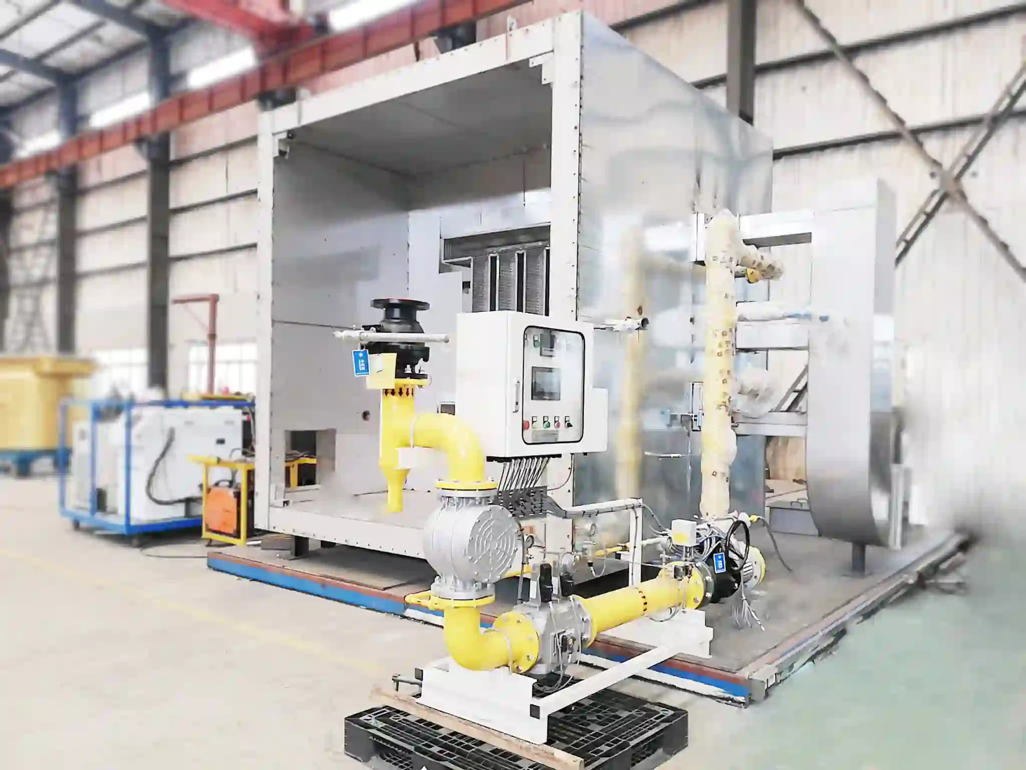
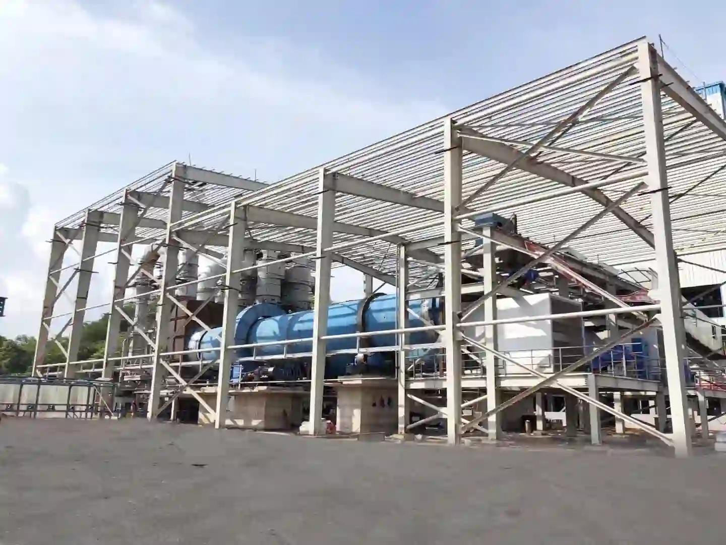
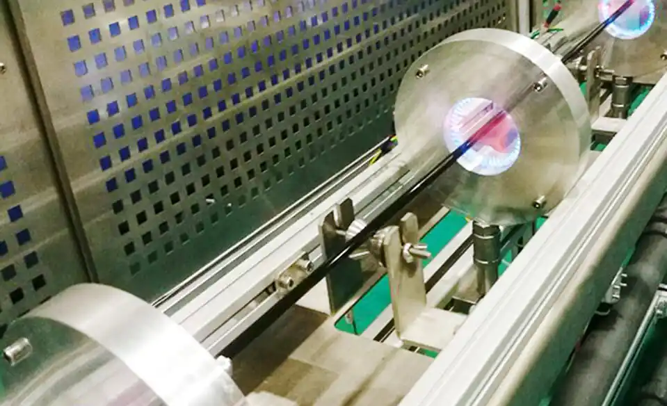
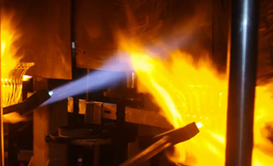
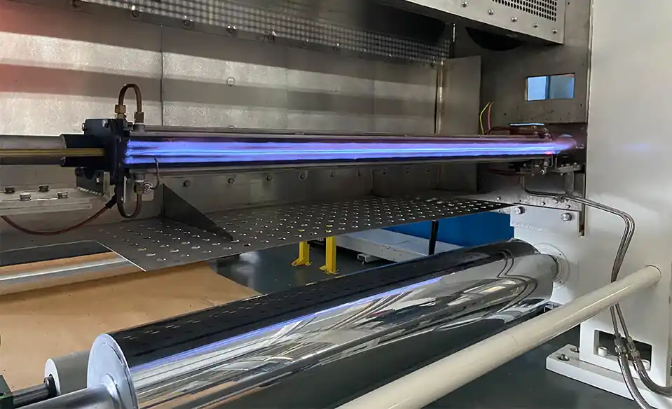
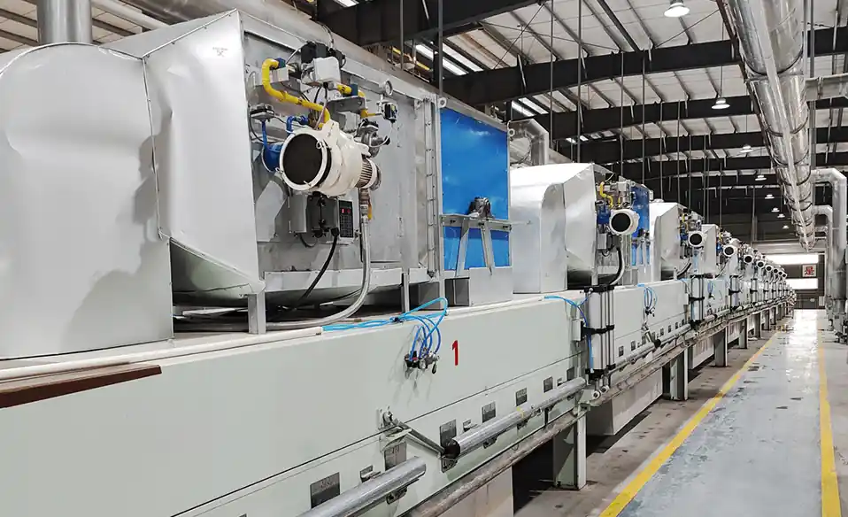
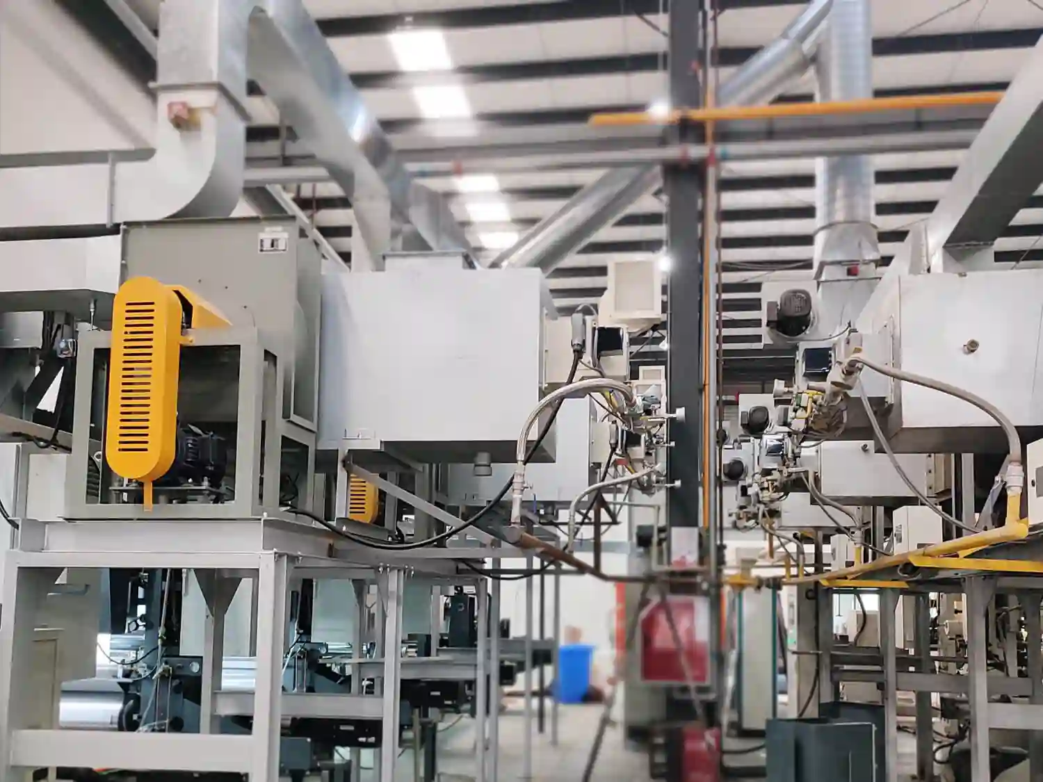
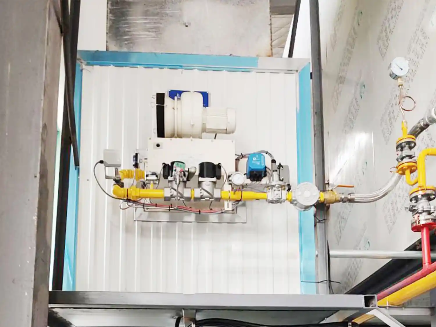
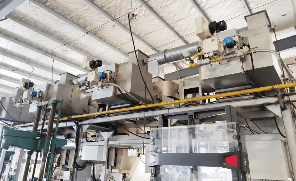
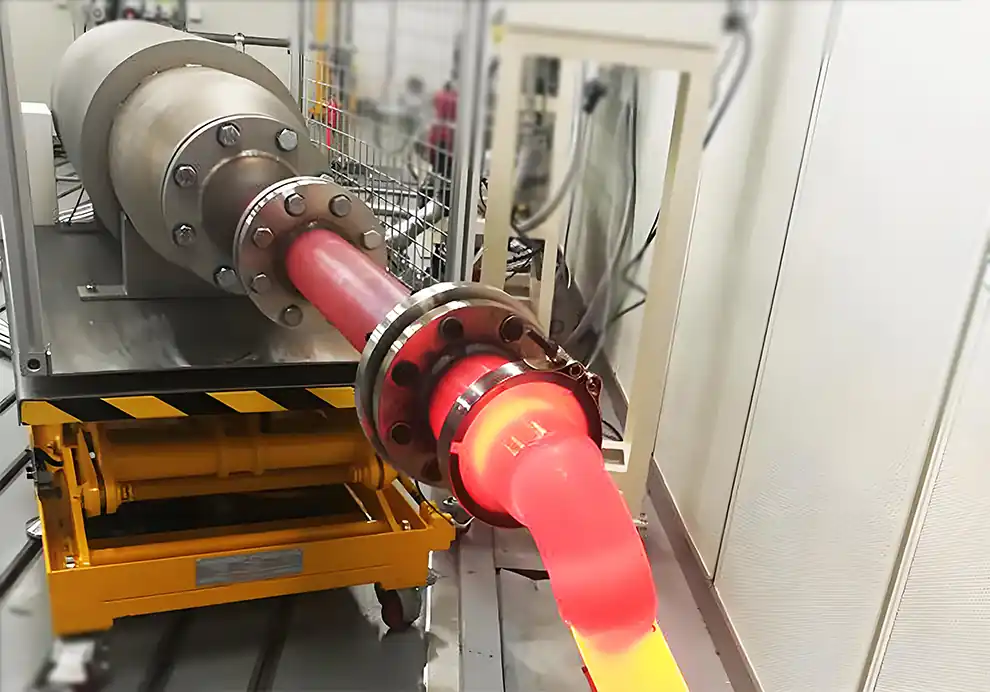
Burners are the core heat-generating components of gas-fired hot air generators. Their primary function is to convert fuel into controlled thermal energy and transfer that energy to an air stream, producing hot air for industrial heating, drying, curing, preheating, and other thermal processes.
A typical hot air generation process can be represented as:
Fuel + Combustion Air
↓
Burner
↓
Combustion
↓
Heat Transfer
↓
Hot Air
↓
Industrial Process
Unlike a conventional furnace, where the flame and combustion gases may directly heat a workpiece, a hot air generator is primarily designed to produce a controlled stream of hot air.
This makes the relationship between the burner and the air-handling system particularly important.
The burner needs to be selected according to:
Required hot-air temperature
Airflow
Thermal capacity
Air inlet temperature
Fuel type
Heating method
Temperature uniformity
Burner turndown
Combustion-air conditions
Hot-air generator geometry
Exhaust conditions
Control requirements
A hot air generator is industrial equipment designed to heat air to a specified temperature and deliver that hot air to a downstream process.
It can be used for:
Industrial drying
Material heating
Coating curing
Agricultural drying
Food processing
Chemical drying
Powder drying
Textile processing
Building-material production
Battery-material processing
Industrial ovens
A typical system consists of several major components:
Burner
Fuel supply
Combustion-air system
Heating chamber
Air circulation or process-air system
Exhaust system
Temperature-control system
Safety and flame-monitoring system
The burner provides the thermal energy, while the rest of the system determines how that energy is transferred and delivered.
The burner converts chemical energy in the fuel into thermal energy.
The process can be simplified as:
Fuel
Combustion Air
↓
Ignition
↓
Stable Flame
↓
Heat Release
↓
Hot Air
The burner therefore determines the amount and characteristics of the heat entering the hot-air generator.
A suitable burner should provide:
Stable combustion
Appropriate heat output
Reliable ignition
Stable low-load operation
Suitable flame characteristics
Accurate heat-output control
The burner should also be compatible with the hot-air generator's airflow and chamber geometry.
There are two common approaches.
In a direct-fired system, combustion gases mix with the process air.
The basic process is:
Burner → Combustion → Hot Gas → Process Air → Downstream Equipment
This configuration can provide high thermal efficiency because the heat generated by combustion is transferred directly to the air stream.
It is commonly considered when the downstream process can accept the resulting combustion gases.
Important considerations include:
Combustion-gas composition
Oxygen concentration
Moisture content
Product sensitivity
Required hot-air temperature
In an indirect-fired system, combustion gases do not directly enter the process-air stream.
Instead:
Burner → Heat Exchanger → Process Air → Hot-Air Outlet
The burner heats a heat exchanger, and the process air is heated separately.
This configuration can be useful when the process requires cleaner hot air or when combustion products must be isolated from the material.
However, heat-exchanger performance becomes an important part of the overall system.
Airflow is fundamental to hot-air generation.
The burner provides thermal energy, but the air system determines how that energy is transported.
The relationship can be simplified as:
Burner Heat Input + Airflow → Hot-Air Output
For a given burner capacity, changing the airflow changes the resulting hot-air temperature.
Generally:
Higher Airflow → Lower Temperature Rise
Lower Airflow → Higher Temperature Rise
Therefore, burner capacity cannot be considered independently from airflow.
The temperature rise of the air depends primarily on:
Burner heat input
Airflow
Air inlet temperature
Heat-transfer efficiency
Heat losses
A simplified relationship is:
Heat Input ≈ Air Mass Flow × Specific Heat × Temperature Rise
This means a burner that is suitable for one hot-air generator may not be suitable for another system with a substantially different airflow.
Burner selection should therefore begin with the required airflow and temperature rise, not just the desired burner capacity.
The hot-air generator should ideally deliver air with a stable and sufficiently uniform temperature.
Temperature fluctuations can affect downstream processes such as:
Drying
Curing
Baking
Preheating
Material treatment
If the hot-air temperature varies significantly, the downstream equipment may experience inconsistent process conditions.
Temperature uniformity depends on more than burner performance.
It can also be affected by:
Mixing chamber geometry
Airflow distribution
Burner position
Flame characteristics
Heat-exchanger design
Fan operation
Burner position determines how combustion heat enters the heating chamber.
Depending on the design, the burner may be installed:
Axially
Laterally
At the end of a combustion chamber
Along a heating chamber
In a dedicated burner chamber
The arrangement should provide sufficient space for combustion and appropriate mixing between hot combustion gases and process air.
Poor burner placement can result in:
Local overheating
Uneven air temperature
Excessive wall temperatures
Poor mixing
Increased thermal stress
Burner angle influences the direction of the flame and combustion gases.
It can affect:
Flame trajectory
Gas circulation
Mixing
Heat distribution
Local temperature
Heat-exchanger loading
The appropriate angle depends on the combustion chamber and air-flow configuration.
The objective is to establish a suitable thermal and mixing pattern rather than simply direct the flame toward the air outlet.
Flame length determines where the main combustion and heat-release region develops.
If the flame is too short, heat may become concentrated near the burner.
If the flame is too long, it may:
Reach chamber walls
Impinge on heat-exchanger surfaces
Create local hot spots
Interfere with downstream airflow
The appropriate flame length depends on:
Burner capacity
Combustion-chamber dimensions
Burner position
Fuel type
Combustion-air conditions
Flame shape influences how thermal energy is distributed.
Depending on the hot-air generator, the burner may require:
Long flame
Short flame
Broad flame
Narrow flame
High-momentum flame
Distributed heat-release pattern
The appropriate flame characteristics should be matched to the heating chamber and airflow.
A burner designed for a furnace is not automatically suitable for a hot-air generator.
The heating chamber geometry has a direct influence on burner performance.
Important parameters include:
Chamber diameter
Chamber length
Chamber cross-sectional area
Burner position
Air inlet location
Hot-air outlet location
Exhaust location
Heat-exchanger position
The burner should be selected according to the actual geometry.
A compact hot-air generator may require a very different burner configuration from a large industrial thermal-air furnace.
Airflow is one of the most important variables.
Consider two systems:
System A
High airflow + moderate temperature rise
System B
Low airflow + high temperature rise
Even if both systems require the same general thermal function, their burner requirements can be substantially different.
Therefore, the OEM should define:
Airflow
Air inlet temperature
Desired outlet temperature
Operating range
before selecting the burner.
An oversized burner may be capable of reaching the target temperature rapidly, but it may become difficult to control at lower heat demand.
Potential problems include:
Temperature overshoot
Excessive burner cycling
Unstable low-load operation
Local overheating
Higher fuel consumption
This is particularly important when the hot-air generator operates over a wide range of process conditions.
An undersized burner may not provide sufficient heat input to achieve the required outlet-air temperature.
Potential consequences include:
Insufficient hot-air temperature
Slow temperature recovery
Reduced production capacity
Longer drying or heating cycles
Inability to maintain the target temperature at maximum airflow
Burner sizing should therefore consider both normal and maximum operating conditions.
Hot-air generators frequently operate at different thermal loads.
For example:
Startup
→ High heat demand
Temperature Approach
→ Reduced heat demand
Stable Operation
→ Modulating heat demand
Reduced Production
→ Lower heat demand
A burner with suitable turndown capability can reduce heat output while maintaining stable combustion.
This helps improve:
Temperature control
Fuel utilization
Operating stability
Response to changing process loads
Combustion air affects the burner's flame characteristics and combustion performance.
The air-to-fuel ratio influences:
Flame stability
Flame temperature
Combustion efficiency
Exhaust volume
Oxygen concentration
Too much combustion air can increase heat losses.
Too little combustion air can result in incomplete combustion and unstable flame behavior.
The combustion-air system therefore needs to be matched to the burner throughout its operating range.
Excess combustion air can influence the thermal output of the system.
When additional air is introduced into combustion, that air must also be heated.
As a result, excessive combustion air can:
Reduce effective temperature rise
Increase exhaust volume
Increase heat loss
Increase fuel demand
The appropriate air-to-fuel ratio depends on the burner design and process requirements.
The exhaust system removes combustion products and, depending on the process, moisture or other process gases.
Excessive exhaust can remove useful thermal energy.
Insufficient exhaust can cause:
Pressure instability
Poor moisture removal
Inadequate removal of combustion products
Unstable operating conditions
The exhaust system should therefore be designed together with the burner and airflow system.
Pressure influences gas movement throughout the system.
Excessive negative pressure may draw unwanted ambient air into the hot-air generator through:
Seals
Doors
Openings
Duct connections
This cold air can reduce outlet temperature and increase energy consumption.
Pressure control should therefore be considered together with:
Burner operation
Fan capacity
Airflow
Exhaust flow
A typical temperature-control loop can be represented as:
Temperature Sensor
↓
Controller
↓
Fuel / Burner Output
↓
Hot-Air Temperature
↓
Temperature Feedback
The system may also control:
Combustion air
Fuel flow
Burner staging
Fan speed
Exhaust flow
Process-air flow
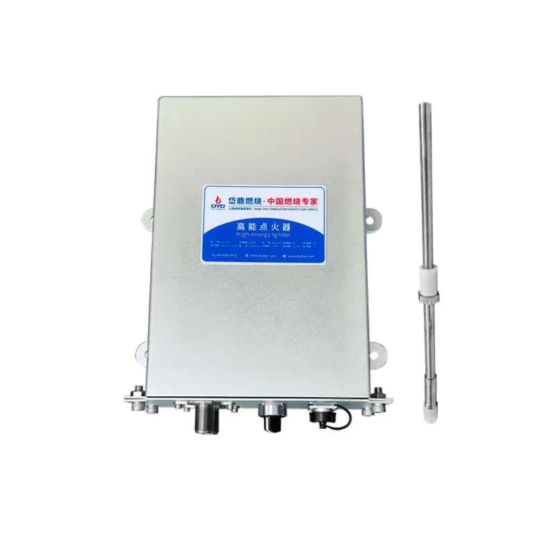
Safety systems generally include functions such as:
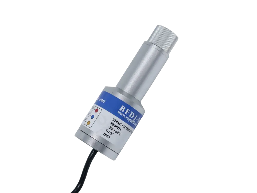
Flame detection
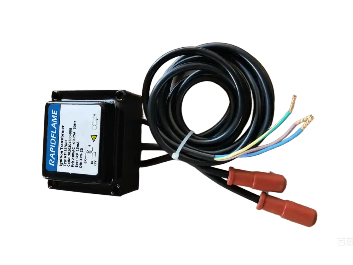
Ignition control
Fuel shutoff
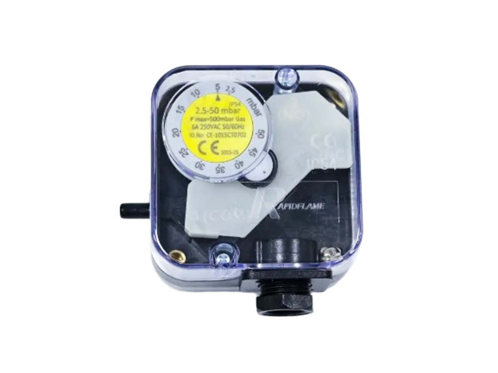
Airflow monitoring
Safety interlocks
Large hot-air generators may use multiple burners when the required thermal capacity or heat distribution cannot be achieved effectively with a single burner.
Multiple burners can provide:
Distributed heat input
Flexible capacity
Multi-zone control
Better load matching
Redundancy in some system configurations
However, multiple burners also require careful coordination of:
Fuel supply
Combustion air
Ignition
Flame detection
Temperature control
System-level optimization is usually more effective than focusing only on burner efficiency.
Select the burner according to the required temperature rise and air volume.
Avoid unnecessary excess air while maintaining stable combustion.
Ensure combustion heat is appropriately transferred to the process-air stream.
Avoid excessive loss of useful thermal energy.
Reduce unwanted cold-air infiltration.
Maintain stable operation under changing heat loads.
Exhaust heat may be recovered for combustion-air or process-air preheating.
Reduce heat losses from the heating chamber and duct system.
Burner capacity alone does not determine the resulting hot-air temperature.
Airflow is directly related to temperature rise and overall heat-transfer performance.
The same burner can produce different outlet conditions depending on the inlet-air temperature.
Poor mixing can create temperature stratification.
The flame must fit the combustion chamber.
Flame direction can affect heat distribution and chamber temperatures.
Too much combustion air can increase heat losses.
The exhaust system directly affects pressure and thermal efficiency.
A burner must remain stable when heat demand decreases.
The burner, air system, chamber, fan, exhaust, and controls should be designed as an integrated hot-air generation system.
A practical selection process can follow these steps.
Determine:
Airflow
Inlet-air temperature
Required outlet-air temperature
Temperature tolerance
Operating range
Consider:
Air heating
Material heating
Moisture evaporation
Equipment heat losses
Exhaust losses
Determine:
Fuel type
Fuel pressure
Fuel availability
Required combustion-air conditions
Determine:
Chamber dimensions
Burner location
Air inlet
Hot-air outlet
Exhaust location
Heat-exchanger configuration if applicable
Determine whether the application requires:
Direct-fired heating
Indirect-fired heating
Evaluate:
Thermal capacity
Turndown ratio
Flame length
Flame shape
Flame momentum
Operating range
Coordinate:
Process-air flow
Combustion air
Mixing
Fans
Ducts
Coordinate:
Exhaust flow
Pressure
Air infiltration
Heat recovery
Coordinate:
Temperature sensors
Fuel modulation
Air control
Fan control
Flame detection
Safety interlocks
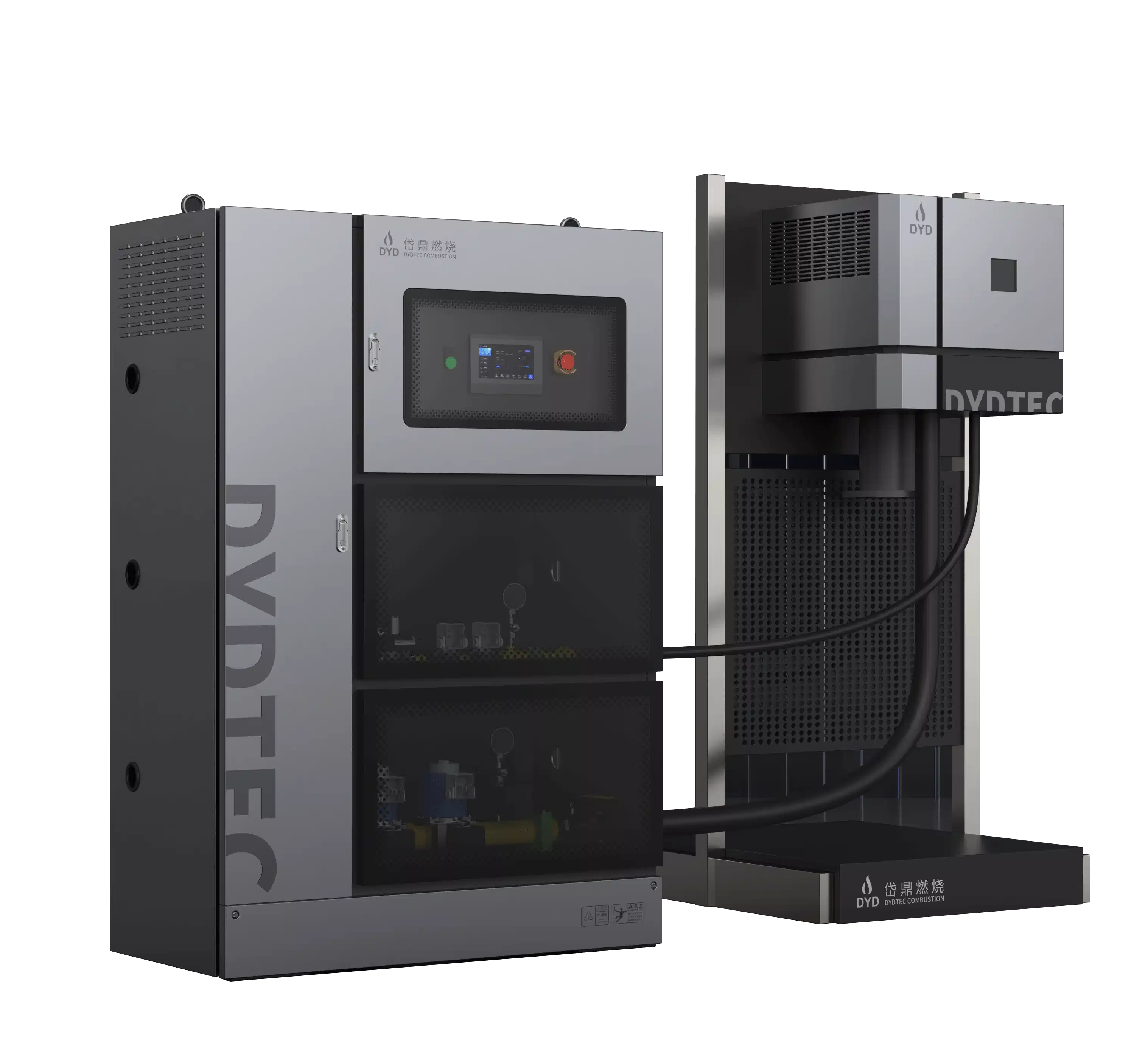
DYDTEC Combustion develops industrial burners, linear burners, thermal air furnaces, and combustion-system integration solutions for industrial heating applications.
For hot air generation, the combustion system can be configured according to:
Required airflow
Temperature rise
Thermal load
Fuel type
Heating method
Chamber geometry
Flame characteristics
Temperature uniformity
Turndown requirements
Control requirements
DYDTEC Combustion has developed 100+ burner models covering 200+ application scenarios, providing different burner configurations for industrial heating and hot-air applications.
The company was established in 2012 and has R&D and manufacturing bases in Shanghai and Yangzhou.
For OEMs, this allows the burner and thermal-air system to be considered together rather than treating the burner as an isolated component.
The burner can affect the design of the complete hot-air generator.
It may influence:
Combustion chamber dimensions
Burner opening
Airflow arrangement
Fan selection
Mixing chamber design
Heat-exchanger configuration
Exhaust arrangement
Temperature-control strategy
If the burner is selected only after the equipment has already been designed, the available options for optimizing the thermal system may be limited.
Early coordination allows:
Burner + Combustion Chamber + Airflow + Heat Transfer + Exhaust + Control
to be developed as one integrated system.
This is particularly important when an OEM needs a customized hot-air generator for a specific drying or heating process.
Before selecting a burner, an OEM should ideally provide:
Required airflow
Inlet-air temperature
Outlet-air temperature
Temperature tolerance
Operating range
Total heat load
Material heating requirements
Moisture evaporation requirements
Heat losses
Startup requirements
Heating-chamber dimensions
Burner installation location
Air inlet
Hot-air outlet
Exhaust location
Heat-exchanger configuration
Fuel type
Fuel pressure
Fuel availability
Process-air flow
Combustion-air pressure
Fan capacity
Duct configuration
Exhaust requirements
This information provides the basis for determining burner capacity, flame characteristics, heating configuration, airflow, and control strategy.
A burner converts fuel into thermal energy and transfers that energy to an air stream to produce hot air for industrial processes.
The burner generates the heat, while the hot air generator integrates the burner with a heating chamber, air system, controls, and other components to produce a controlled hot-air stream.
Yes. In direct-fired systems, combustion gases mix with the process air and transfer heat directly.
It uses a heat exchanger to transfer heat from combustion gases to process air without directly mixing the two streams.
For a given thermal input, increasing airflow generally reduces the temperature rise, while decreasing airflow generally increases the temperature rise.
It allows the burner to adjust thermal output as airflow and process heat demand change while maintaining stable combustion.
Burner angle affects flame trajectory, combustion-gas circulation, mixing, and heat distribution inside the heating chamber.
The flame needs to fit the combustion-chamber dimensions. An excessively short or long flame can create uneven heat distribution or local overheating.
Yes. Excessive combustion air increases the amount of gas that must be heated and exhausted, which can increase thermal losses.
Yes. Excessive exhaust can remove useful thermal energy, while insufficient exhaust can cause pressure and process problems.
Yes. Natural gas burners can be used when the burner and complete combustion system are designed for the required airflow, temperature, fuel pressure, and process conditions.
Ideally, burner selection should be considered during the early design stage so that the burner, combustion chamber, airflow, exhaust, and control system can be properly coordinated.
Burners are the heat source at the heart of a hot air generator, but the burner's performance cannot be evaluated independently from the air system.
The overall thermal performance depends on:
Burner Capacity
Airflow
Temperature Rise
Flame Characteristics
Heating Chamber Geometry
Mixing
Exhaust
Pressure Control
Temperature Control
The objective is not simply to generate a high-temperature flame. It is to convert fuel into a stable, controllable, and uniform hot-air stream that meets the requirements of the downstream industrial process.
For OEM manufacturers, burner selection should therefore begin with the required airflow, temperature rise, thermal load, fuel, and equipment geometry.
The right hot-air-generator burner is not simply the burner with sufficient heat capacity. It is the combustion system that matches the required airflow, temperature rise, chamber geometry, flame characteristics, fuel, exhaust, and control strategy to produce stable and uniform hot air for the process.