Output Maximization: Sustains or boosts steam turbine output during gas turbine partial-load operations or high ambient temperature conditions.
Operational Flexibility: Allows combined cycle power plants (CCPP) to maintain high steam parameters at part load to fulfill industrial cogeneration or peak-shaving demands.
Oxygen Utilization: Utilizes the residual oxygen (~15–17% (O_{2})) present in the gas turbine exhaust for combustion, eliminating the need for an external combustion air supply.

(HRSG Duct Burner)
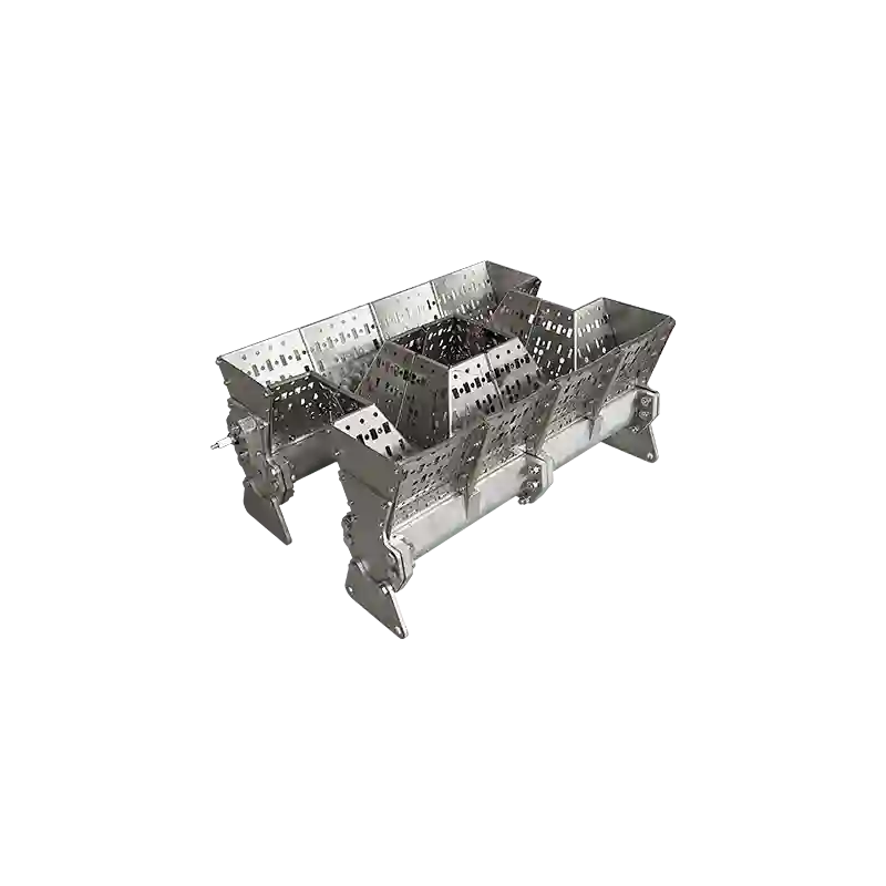
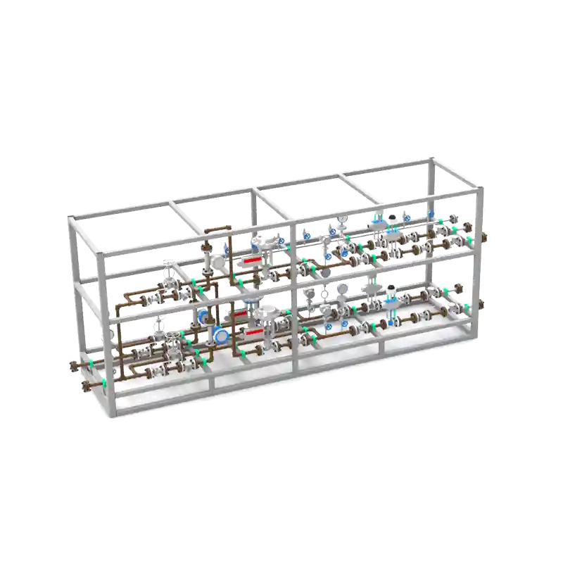
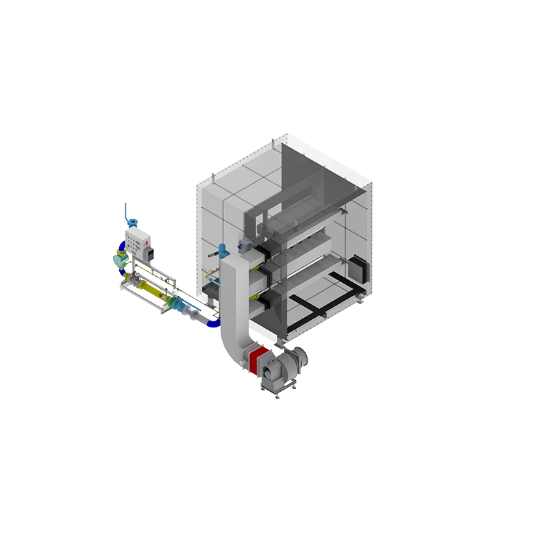
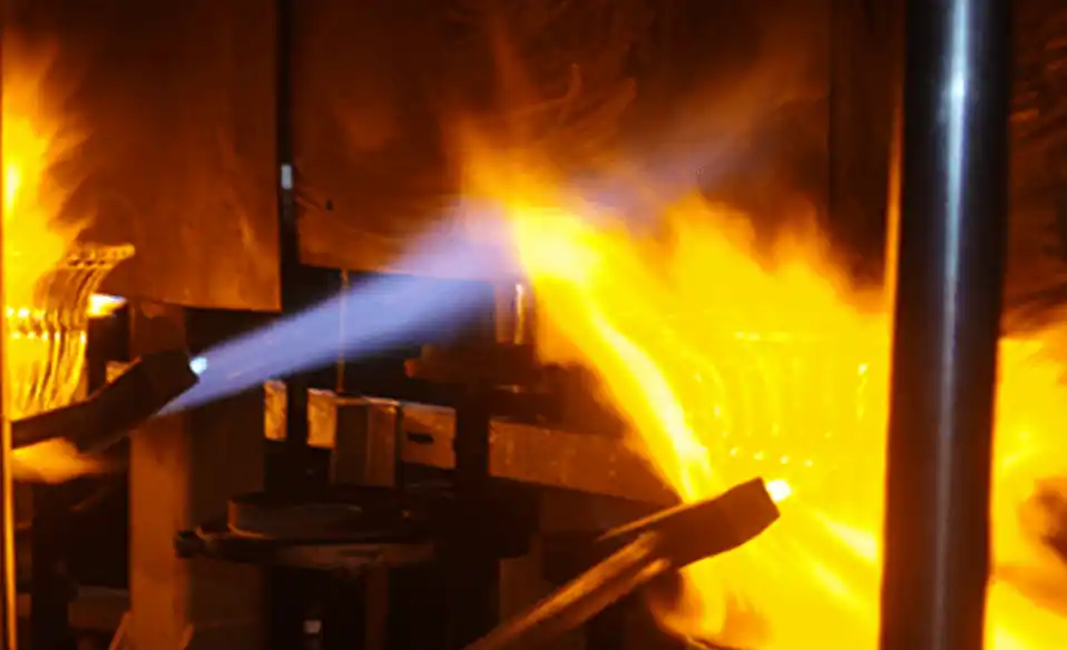
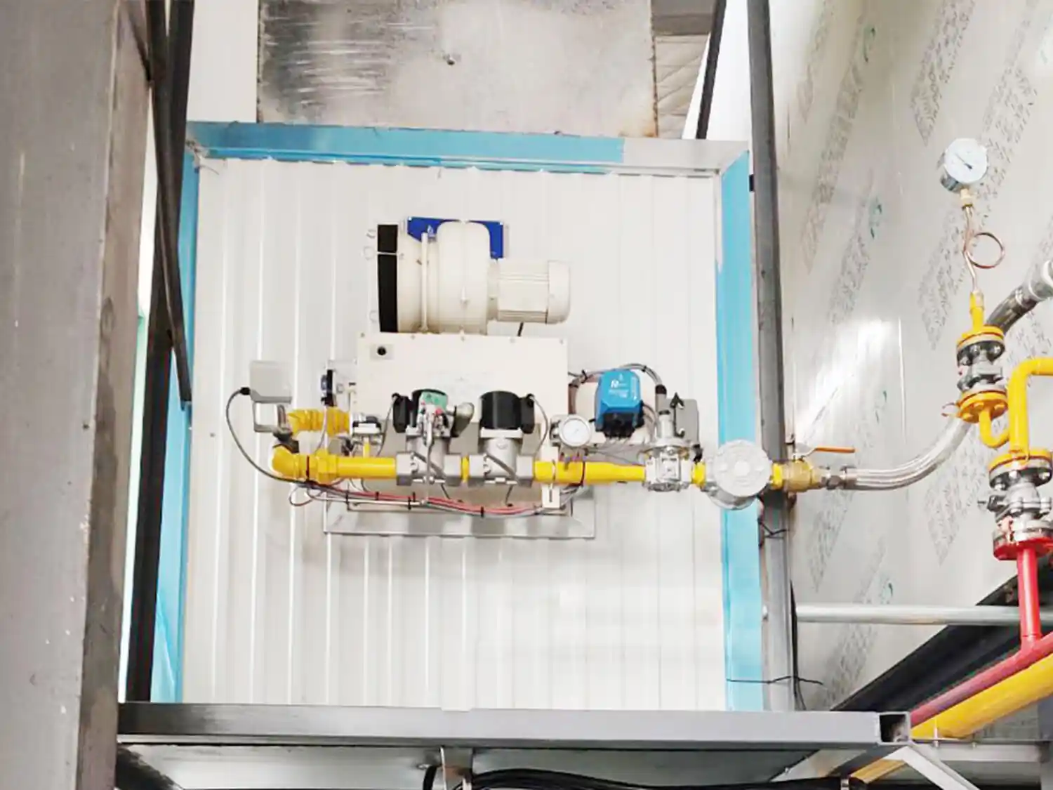
Design & Construction: Consists of multiple parallel fuel headers and lances extending across the HRSG inlet duct. It utilizes V-shaped or serrated vane flame stabilizers to generate a low-velocity recirculation zone within the high-velocity exhaust stream. Ignition and flame detection systems are distributed across the duct width.
Working Principle: Gas turbine exhaust flows past the stabilizer at velocities of 15–25 m/s, forming downstream vortices. Natural gas is injected perpendicularly into these zones, igniting via the high-temperature exhaust gas to produce a short flame ((< 1text{ m})) that avoids direct impingement on tube bundles.
Performance Metrics:
Advantages: Compact footprint, low pressure drop (100–200 Pa), low capital expenditure (CAPEX), and simplified maintenance.
Limitations: Flow profile uniformity depends strictly on stabilizer geometry. Thermal hot spots can occur in ducts wider than 4 meters. Temperature rise is limited (corrosion risks escalate above (200^{circ }text{C})).
Critical Design Parameters:
Orifice Sizing: Fuel orifice diameter and spacing must match the local exhaust oxygen content (15–17%) to prevent localized reducing atmospheres.
Materials: High-temperature stainless steel alloys (e.g., 253MA, 309S), occasionally enhanced with ceramic coatings.
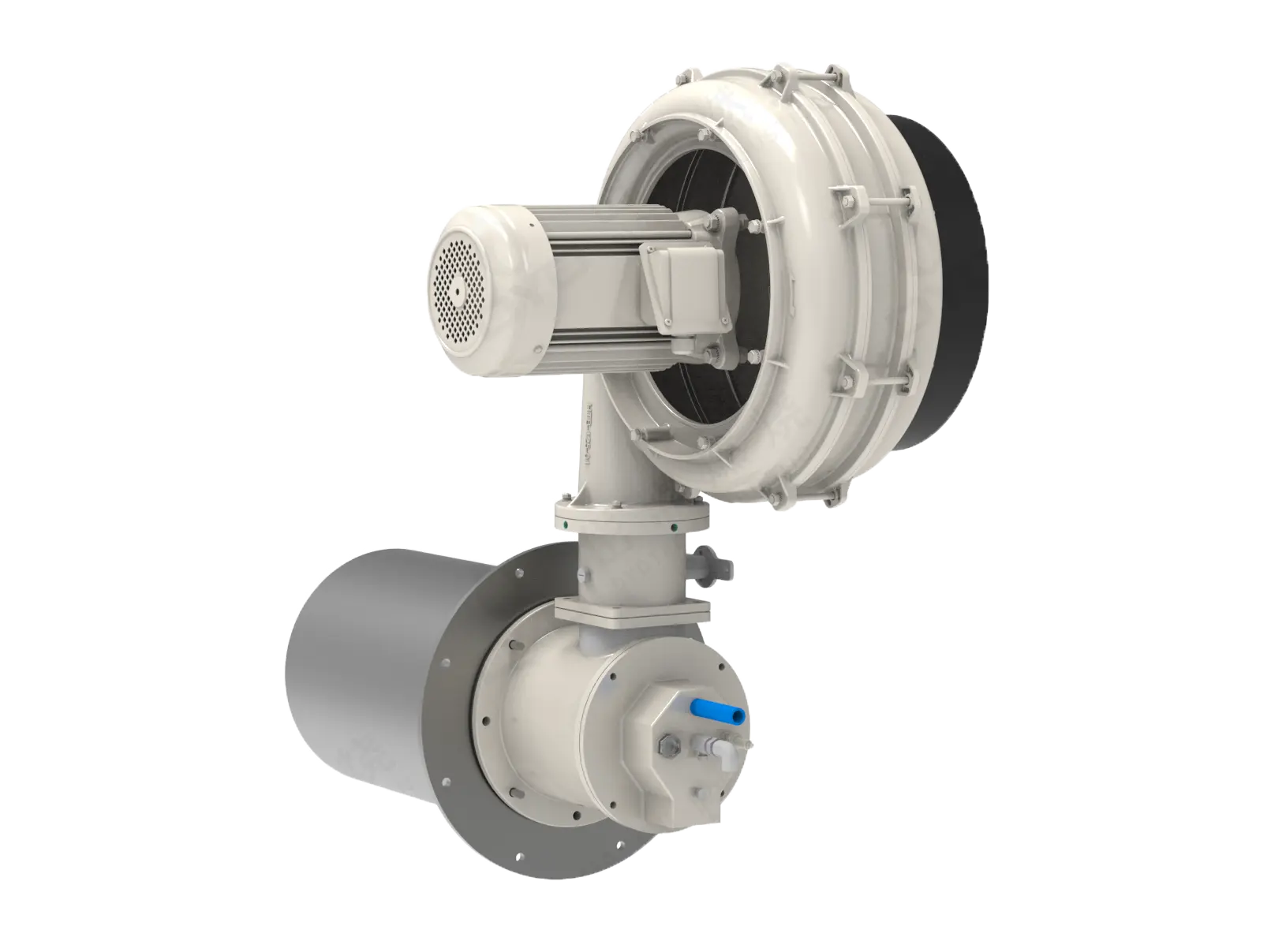
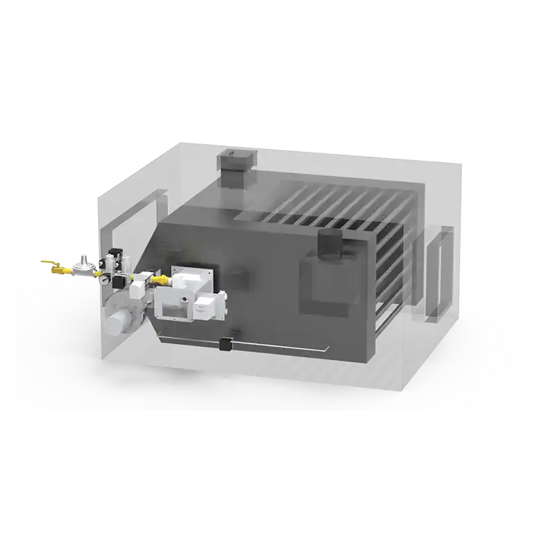
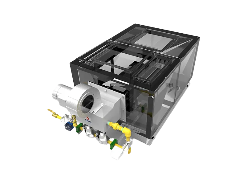
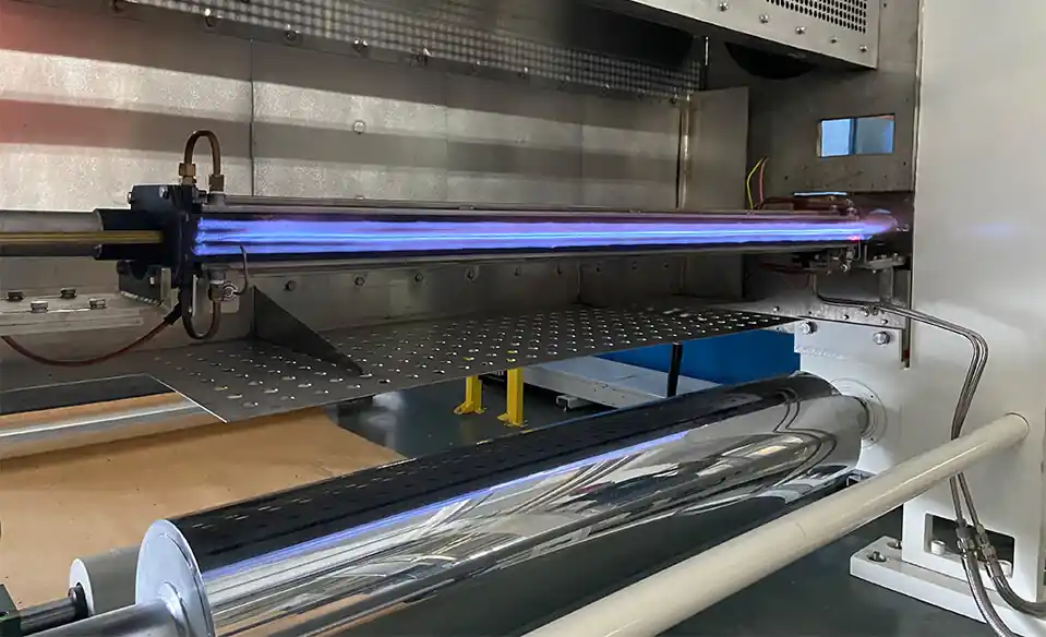
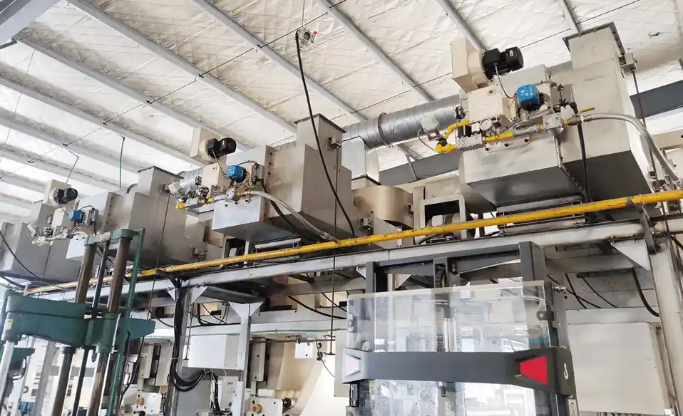
Design & Construction: Features a grid array (e.g., 5×8 configuration) covering the duct cross-section. Each individual burner element integrates a dedicated fuel nozzle and a swirl stabilizer or bluff body. Elements are zoned for independent fuel profiling. Internal duct walls require refractory linings to mitigate high radiant heat flux.
Working Principle: Each individual nozzle establishes an independent micro-flame. The collective matrix distributes heat evenly across the cross-sectional area, preventing localized peak flame temperatures and maintaining uniform heat flux.
Performance Metrics:
Advantages: Superior temperature uniformity (thermal deviation coefficient (<0.1)), supports high temperature rises (300–400°C), and minimizes NOx emissions (20–30 ppm via staged combustion).
Limitations: High mechanical complexity, higher manufacturing costs, requires specialized wall cooling, and exhibits a higher pressure drop (300–400 Pa).
Critical Design Parameters:
Element Pitch: Nozzle spacing typically ranges between 400–800 mm based on flame envelope and entrainment calculations.
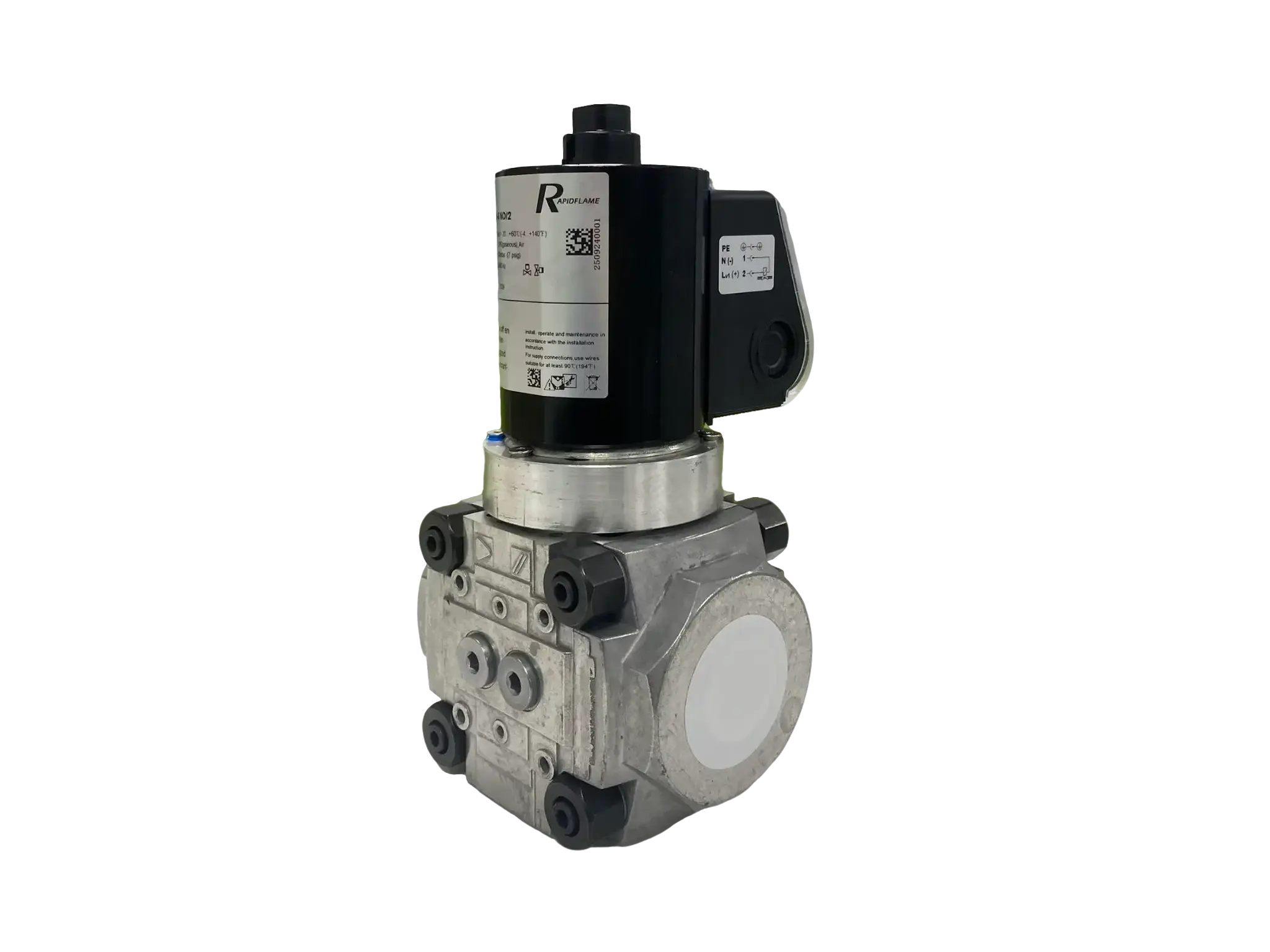
Combustion Control: Rapid-response fuel control valves per zone prevent localized carbon monoxide (CO) formation or excessive NOx peaks.
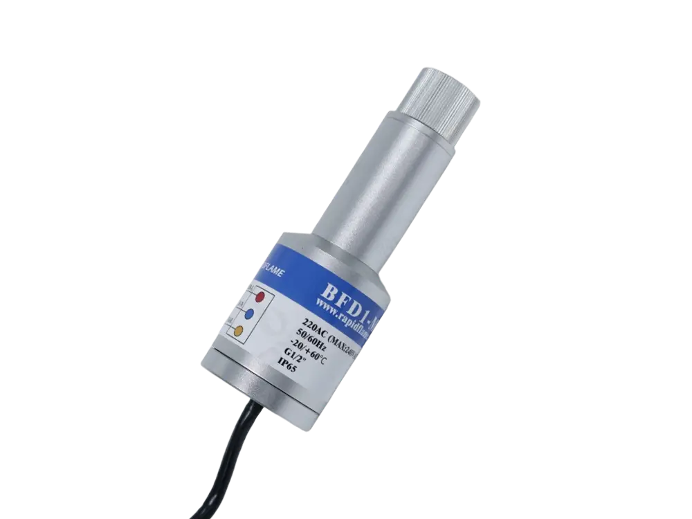
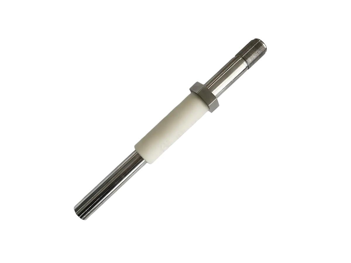
Flame Monitoring: Arrayed ultraviolet (UV) flame detectors or ionization rods.
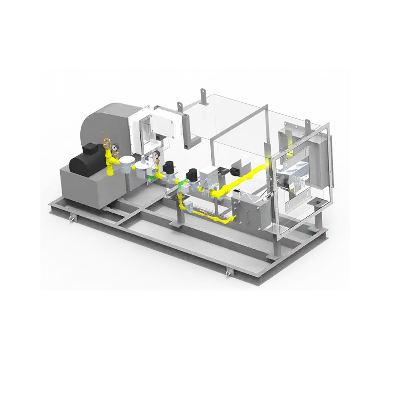
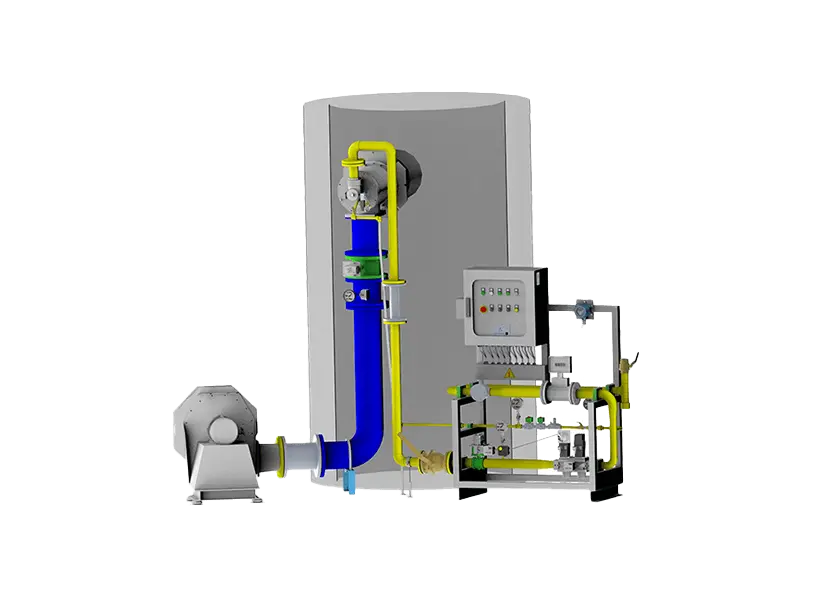
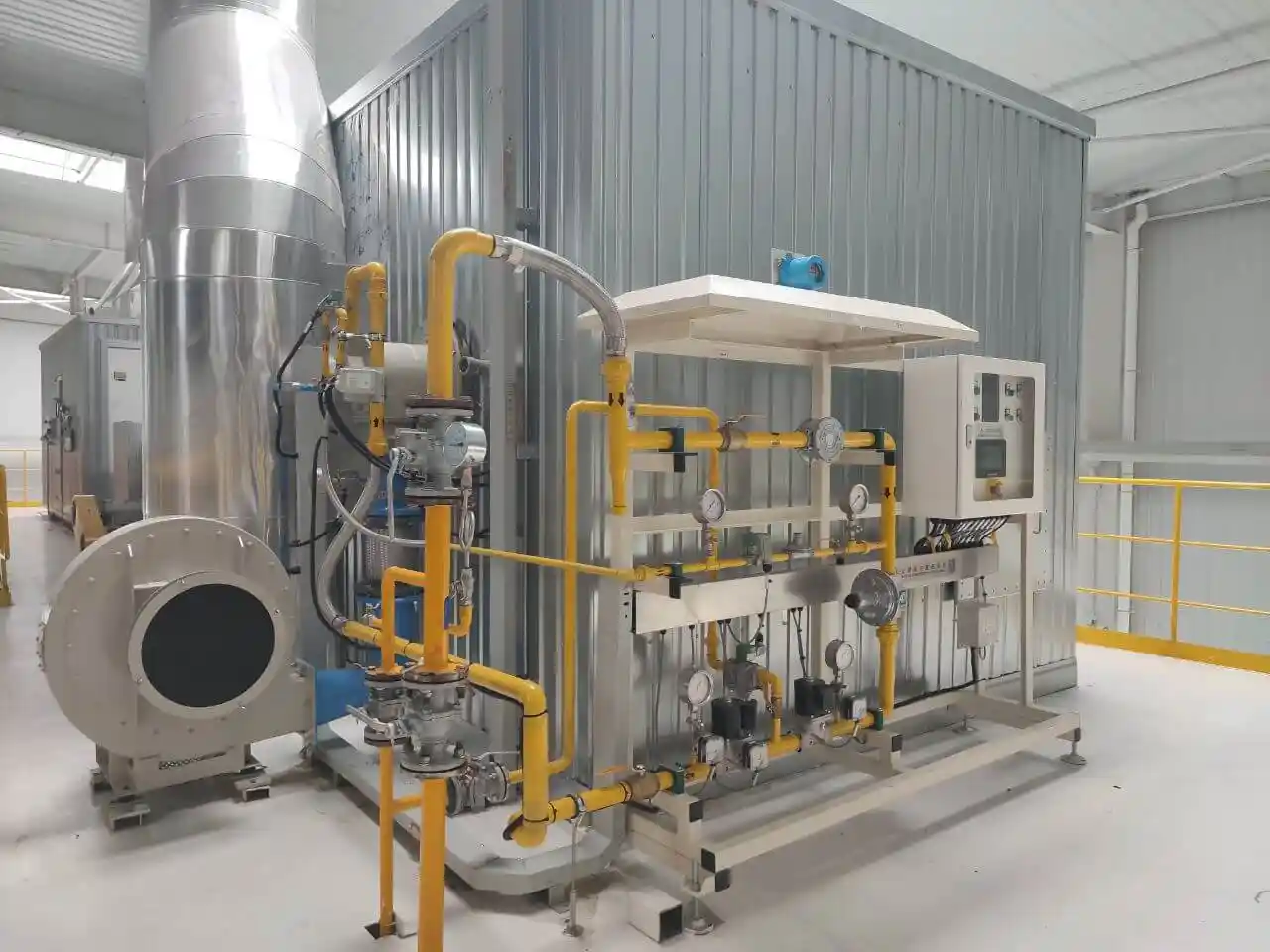
System Design: Integrates a secondary bypass duct parallel to the main HRSG casing housing an independent burner system. Hot combustion gases from the bypass blend with the primary exhaust stream upstream of the target tube banks.
Key Features: Increases mixed gas temperatures effectively during low-load gas turbine operations without disrupting main duct hydraulics. Requires additional footprint and high-temperature zero-leakage dampers.
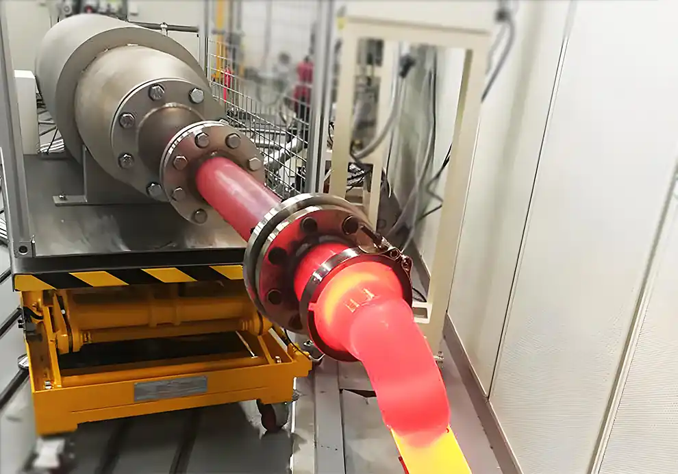
System Design: Burners are positioned within intermediate duct sections—typically downstream of the high-pressure (HP) superheater and upstream of the reheater or low-pressure (LP) evaporator surfaces.
Key Features: Adjusts reheat steam temperatures independently without over-attemperating the main steam line. Flue gas temperatures in this zone can exceed (850^{circ }text{C}), demanding Inconel 617 alloys or specialized internal insulation.
System Design: Modulates fuel delivery to ignite only a specific segment of a matrix burner array (e.g., the central 33% of the duct area) during low-load periods.
Key Features: Provides high turndown ratios with minimal gas-side pressure drop. Resulting thermal profiles are highly non-uniform, making this configuration suitable only for systems tolerant of thermal stratification, such as saturated steam generation.
| Burner Type | Typical Temperature Rise | Temperature Uniformity | Pressure Drop (Pa) | Relative CAPEX | Application Scale |
|---|---|---|---|---|---|
| Duct Burner (Pipe Type) | 50 – 150 °C | Moderate ((pm 20^{circ }text{C}) deviation) | 100 – 200 Pa | Low | Small to Large ((le 300text{ MW}) GT) |
| Multi-Nozzle Matrix | 150 – 400 °C | High ((<pm 5^circtext{C}) deviation) | 300 – 500 Pa | High | Utility Scale ((ge 200text{ MW}) GT) |
| Bypass Firing | Mixed (le 200^{circ }text{C}) | Moderate | Base + Damper Loss | Medium-High | Space-constrained retrofits |
| Zone-Based Firing | Localized High Rise | Low (Diffusion-dependent) | Very Low | Medium | Specialized process cycles |
(le 120^{circ }text{C}) Rise: Conventional pipe-type duct burners provide sufficient thermal performance.
150°C – 250°C Rise: Requires matrix burners or high-capacity duct burners equipped with low-NOx fuel lances.
(>250^{circ }text{C}) Rise: Multi-nozzle matrix burners are mandatory; internal duct casings must feature refractory lining.
Exhaust Velocity: Velocities below 12 m/s require flashback arrestors to prevent flame propagation upstream. Velocities exceeding 25 m/s require high-aerodynamic-drag flame stabilizers to prevent flame blow-off.
Oxygen Thresholds: Exhaust oxygen levels below 13% (common in steam/water-injected gas turbines) degrade flame stability and may necessitate supplemental combustion air integration.
HP superheater tube metal temperatures remain below metallurgical design limits (typically 650–700°C).
Circumferential thermal deviation between adjacent tubes is maintained below 15% to mitigate differential thermal expansion and creep damage.
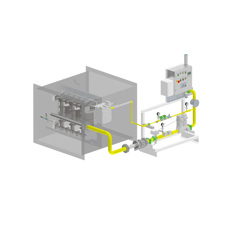
Intelligent Zone Control: Utilizes real-time infrared thermography or thermocouple grids to dynamically trim fuel distribution to individual matrix zones, optimizing the downstream temperature profile.
Hydrogen ((H_{2})) Co-firing & Monofuel Firing: Adapting burners to handle high-flame-velocity hydrogen combustion. Requires specialized burner materials to counter hydrogen embrittlement and updated flashback prevention systems.
Thermal Energy Storage (TES) Integration: Coupling supplemental duct firing with molten salt storage loops to enable energy time-shifting strategies ("power-to-heat-to-power").