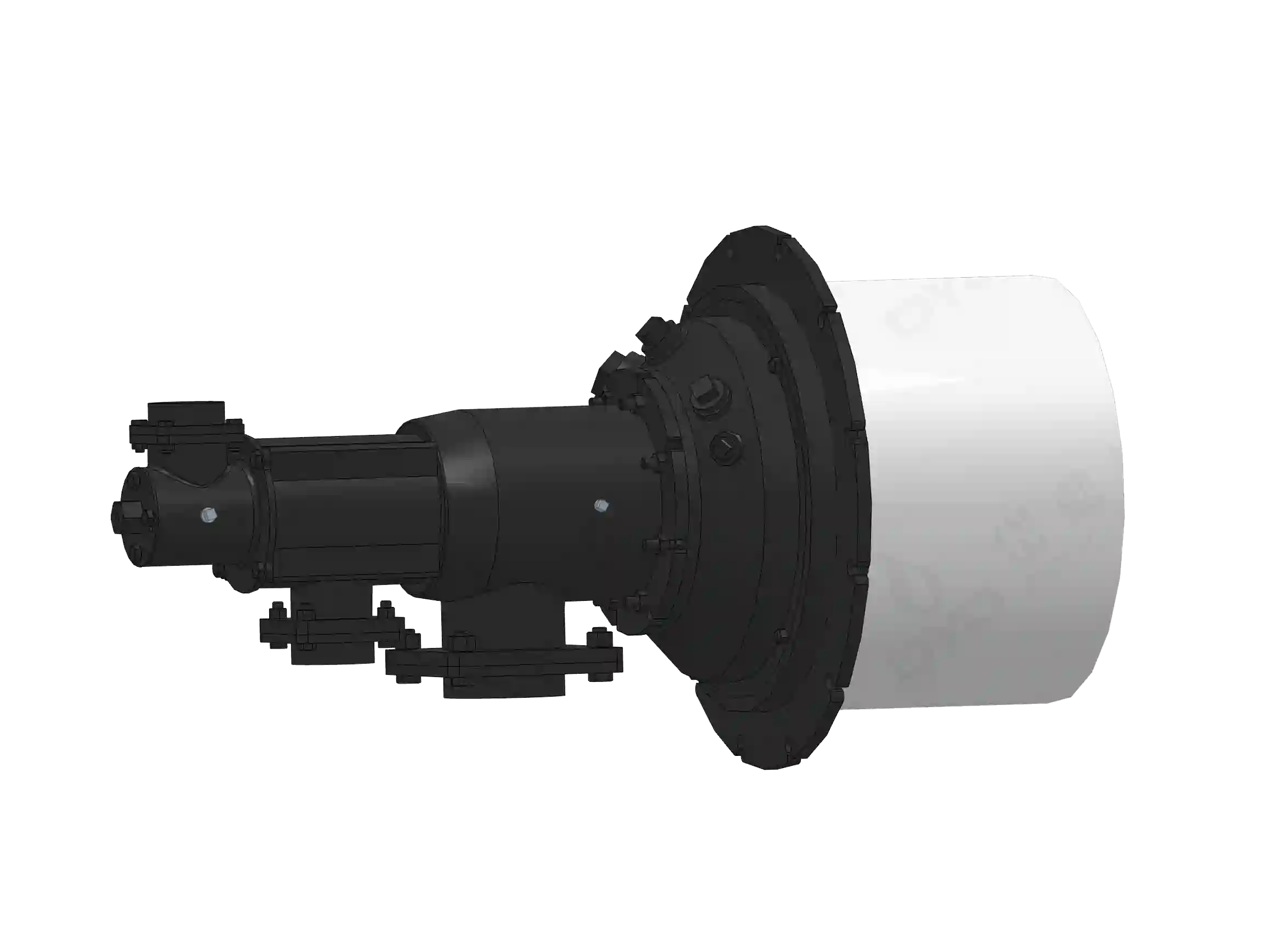
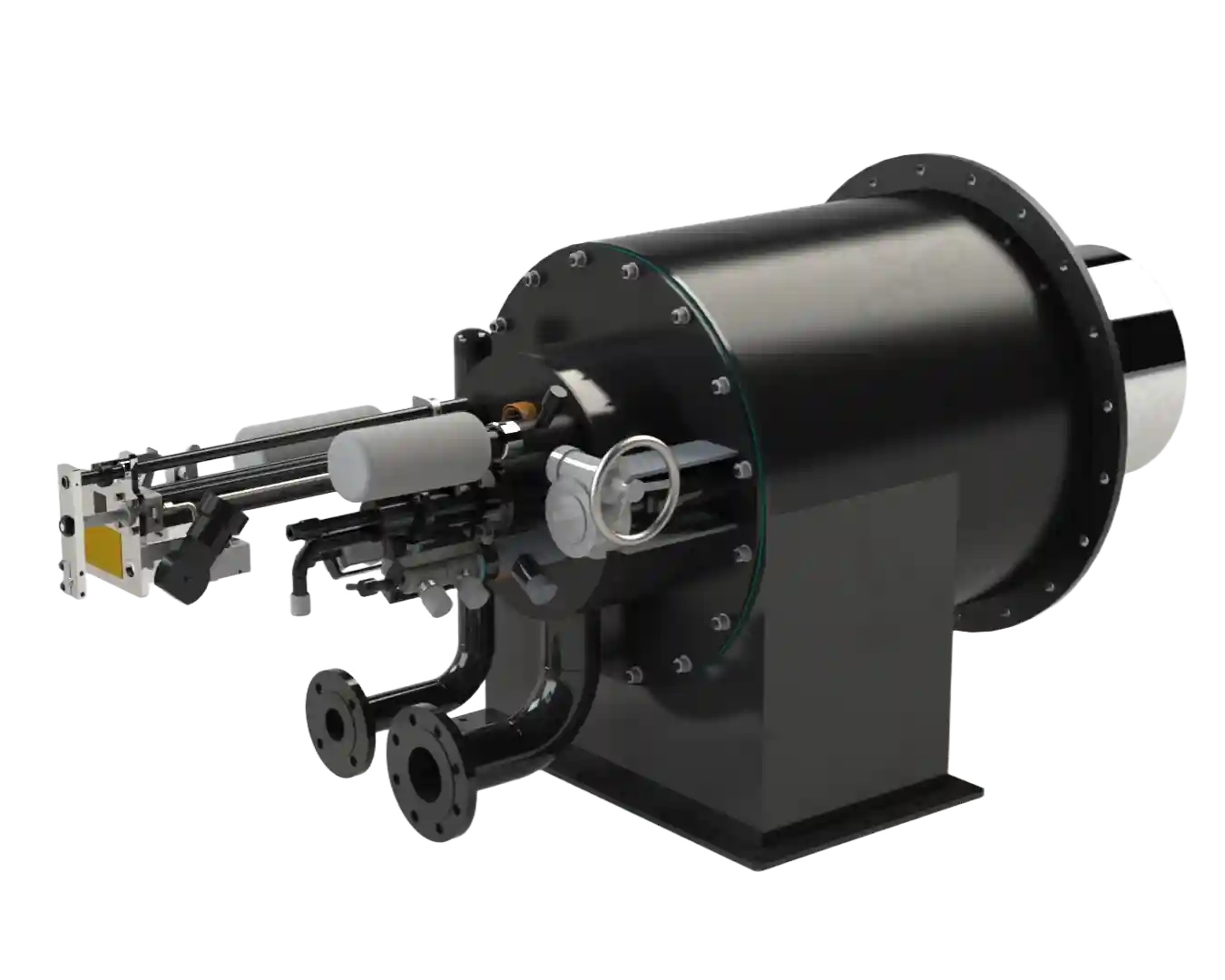
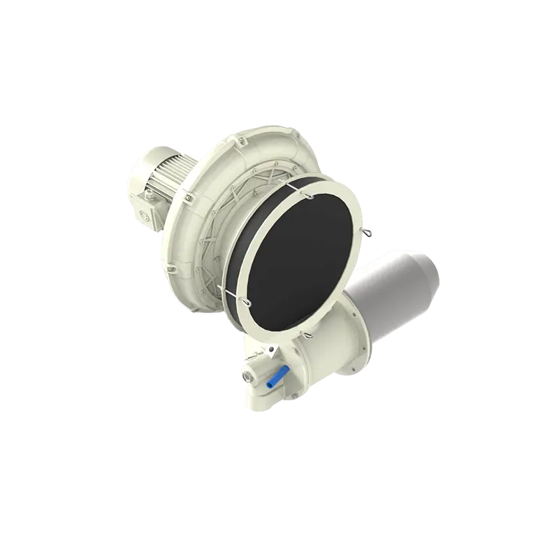
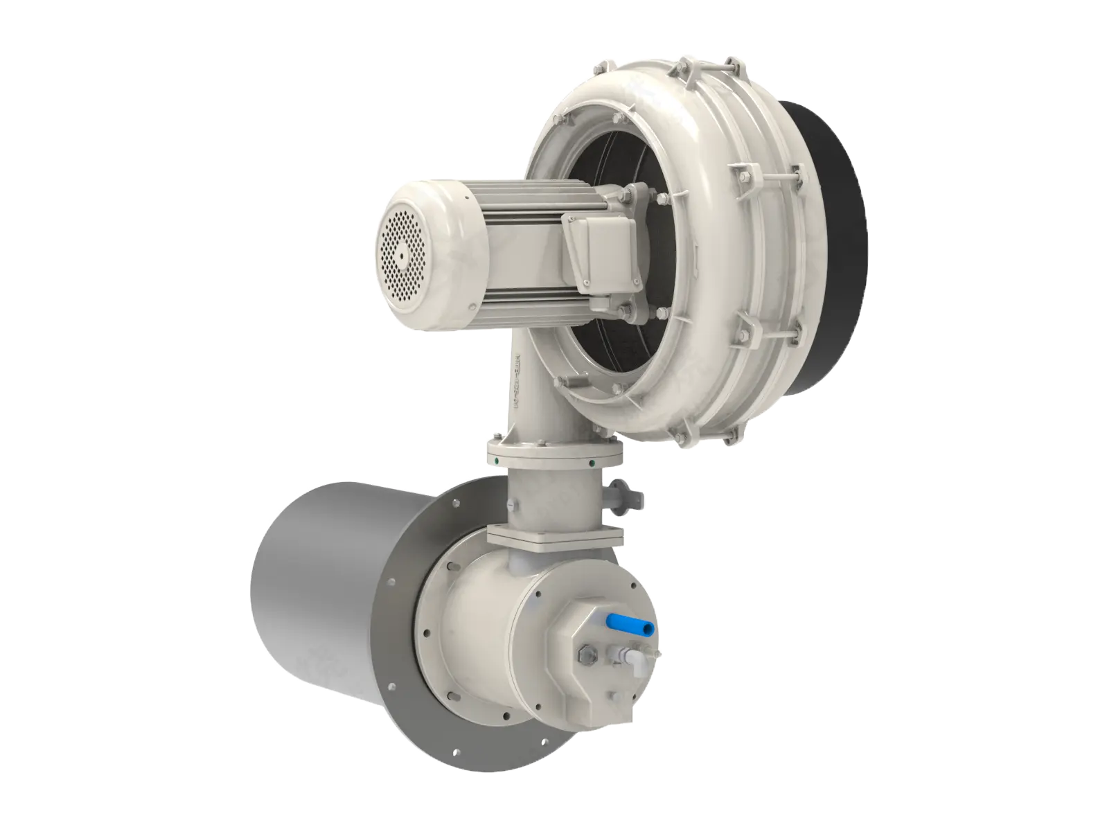
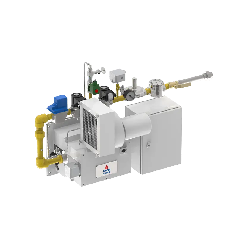
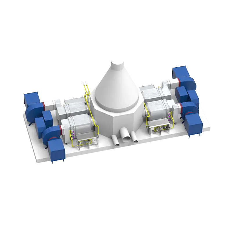
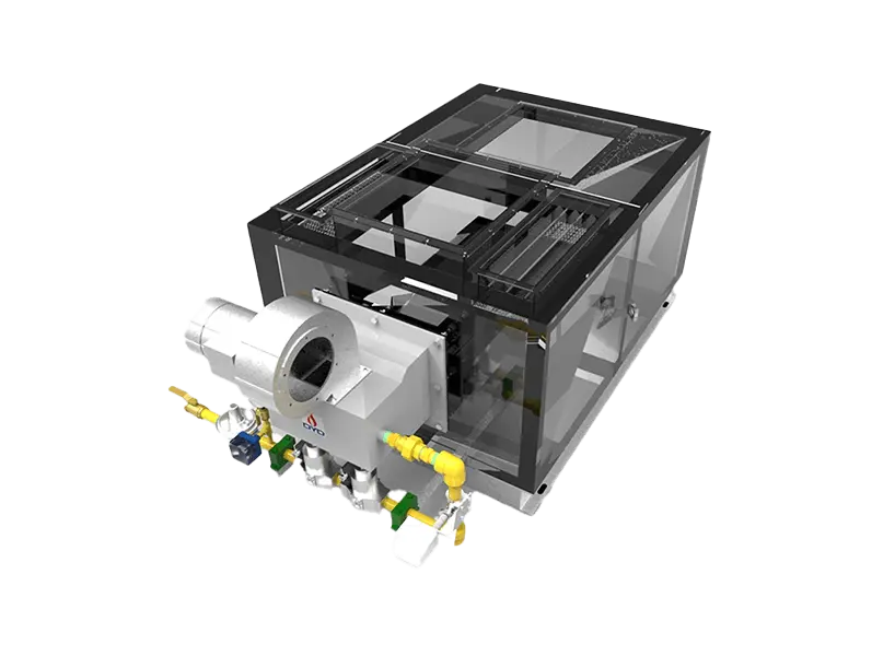
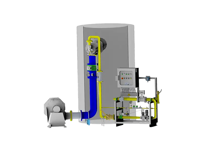
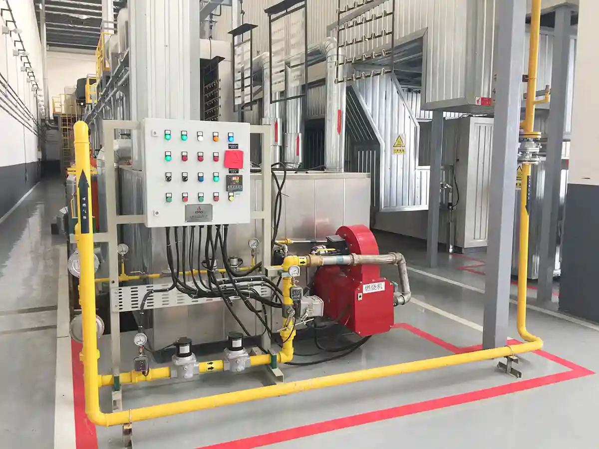
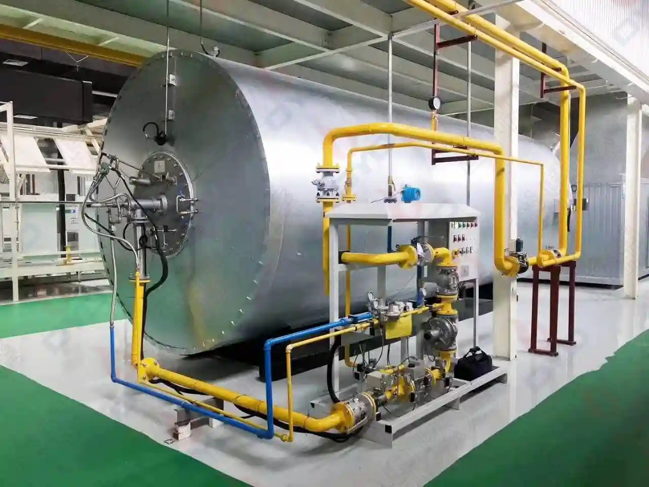
In industrial heating, boiler systems, and gas turbines, the burner is the core device for efficient energy conversion. Understanding its internal architecture and critical components — especially the fuel nozzle, flame stabilizer (V‑type and annular), igniter, flame detector, and damper actuator — is essential for system optimization, fault diagnosis, and safe operation.
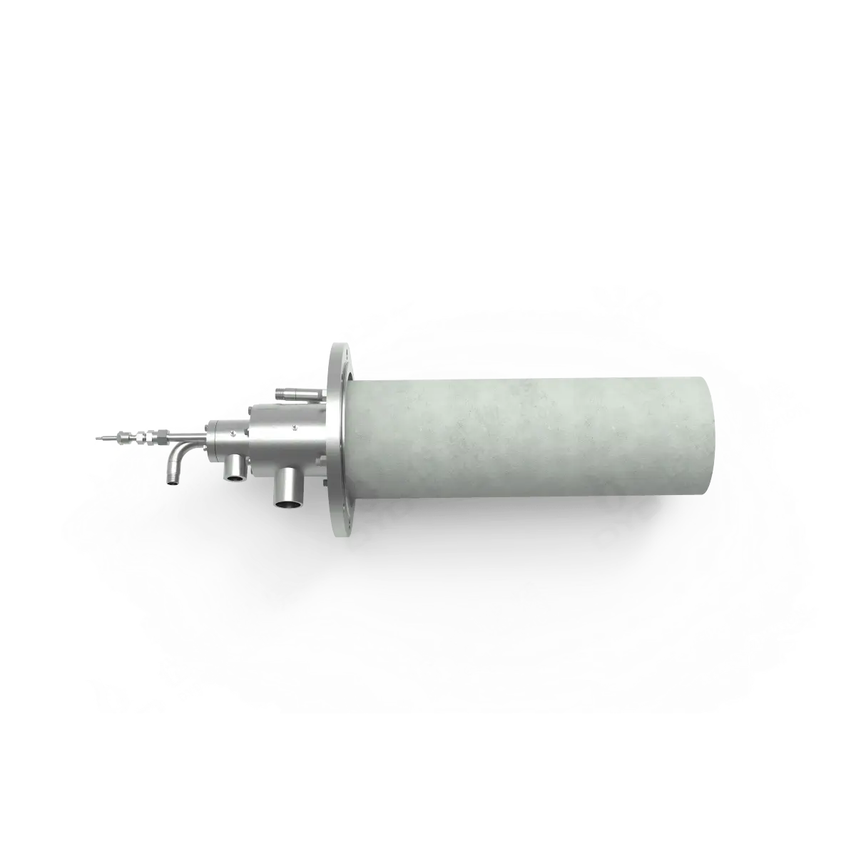
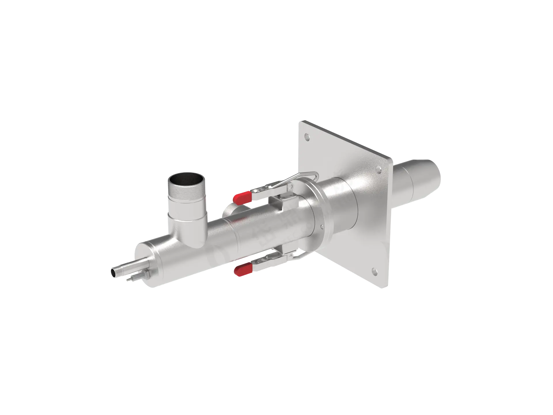
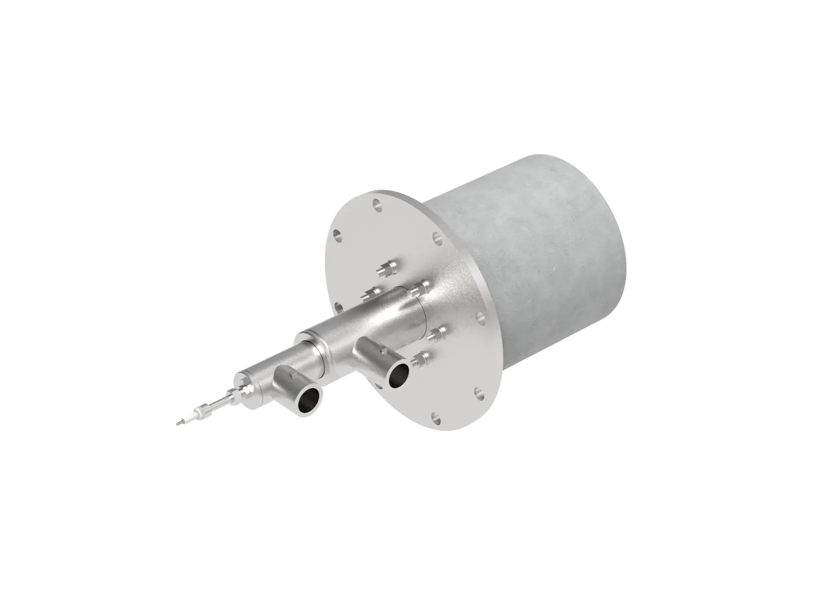
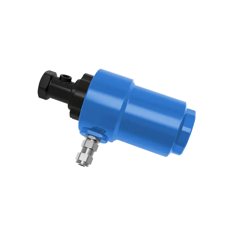
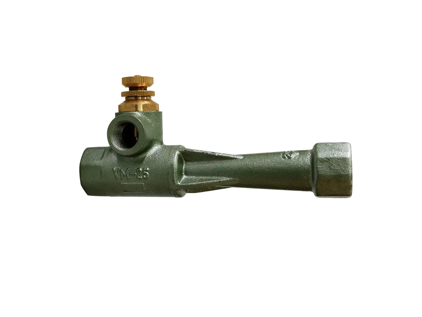
The fuel nozzle injects liquid or gaseous fuel into the combustion zone with a defined spray pattern. Its design directly impacts mixing uniformity and combustion efficiency.
Construction – Typically consists of an orifice body, swirl insert, sealing gasket, and strainer. Liquid fuel nozzles incorporate tangential slots or helical passages to induce fuel rotation for atomization.
Working principle – High‑pressure fuel passes through a small orifice, causing a sharp pressure drop that breaks the liquid into fine droplets (Sauter mean diameter typically 30–80 µm). Gas fuel nozzles use multiple ports or slits to ensure sufficient jet penetration and air entrainment.
Types:
Pressure‑swirl (mechanical) atomizer – Simple, pressure‑driven; suitable for small to medium boilers.
Medium‑assisted atomizer (steam/air) – Finer droplets; handles high‑viscosity fuels.
Twin‑fluid nozzle – High‑speed gas shears the liquid film; offers a wide turndown ratio.
Common failure modes – Orifice wear (flow coefficient drift), coking/plugging (heavy fuel oil), and seal leakage.
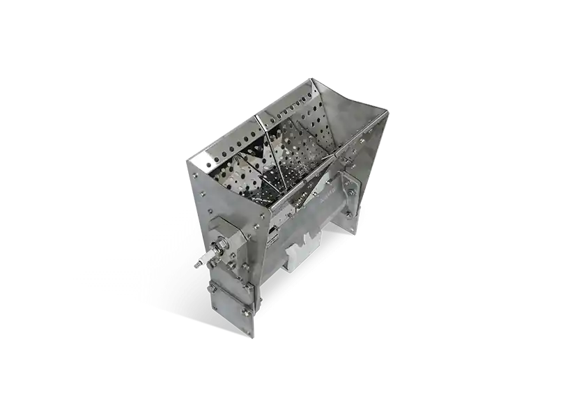
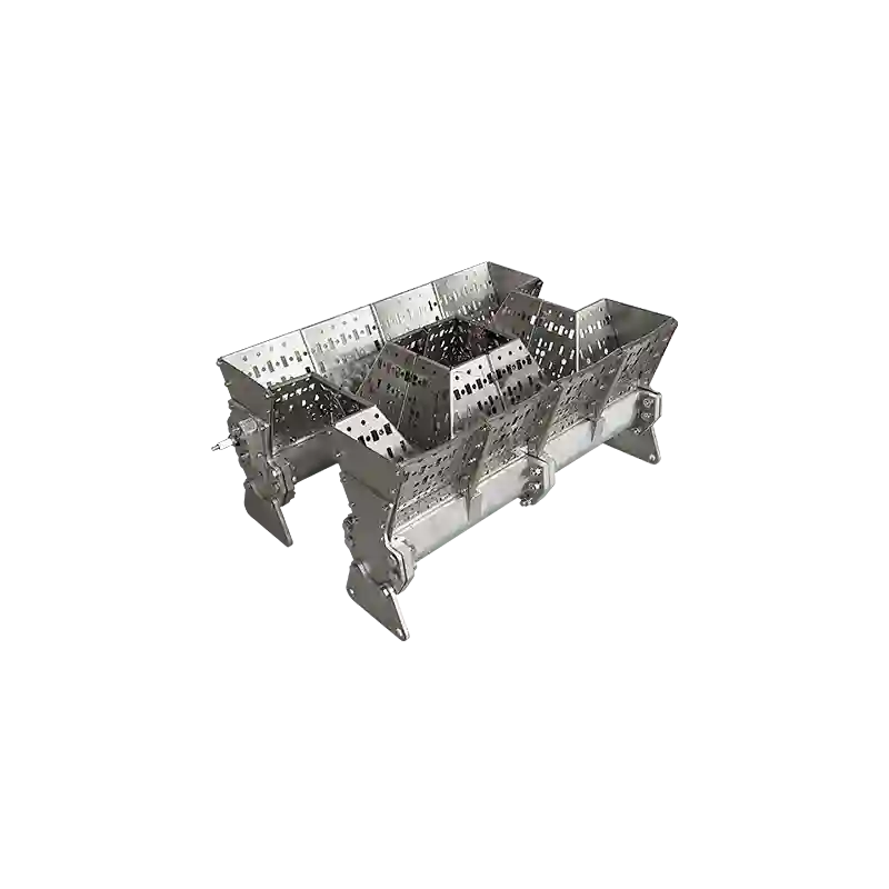
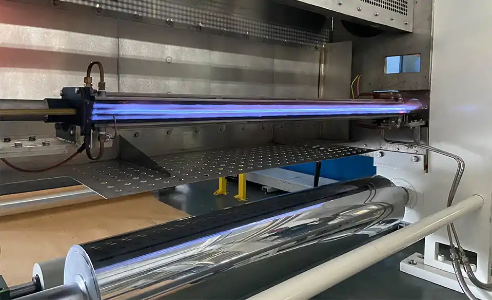
Flame stabilizers create low‑velocity recirculation zones that anchor the flame, preventing blow‑off or flashback. In industrial burners, V‑type and annular designs are most common.
Geometry – Cross‑section shaped like a “V” groove, arranged with the apex facing upstream or the tip pointing downstream, depending on design.
Aerodynamics – As the high‑speed mixture flows past the V‑edge, a pair of counter‑rotating vortices forms behind it. The core pressure drops, drawing hot combustion products back to continuously ignite the fresh mixture. Blow‑off velocity ratio can be improved by a factor of 2–5.
Applications – Gas turbine combustors, high‑velocity industrial burners; excellent for low‑calorific fuels.
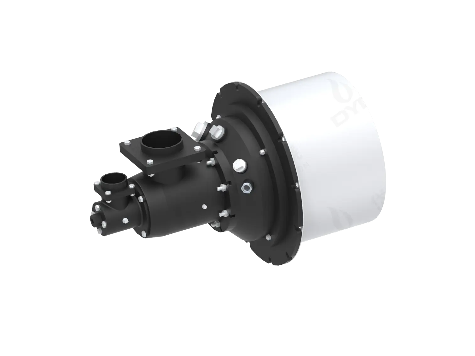
Structure – Concentric cylinders or perforated ring plates, often combined with a swirler. The airflow rotates as it passes through the annular gaps, generating a central recirculation zone.
Advantages:
Uniform circumferential flame, minimizing hot spots.
Wide turndown ratio (up to 1:10 or more) suitable for lean‑premixed low‑emission combustion.
Compact integration with the fuel nozzle.
Comparison – V‑type excels at very high flow velocities; annular is preferred for low‑NOx designs and multi‑fuel flexibility.
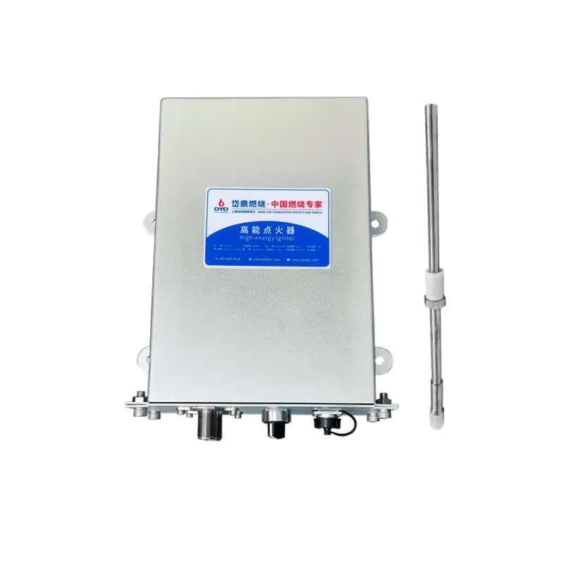
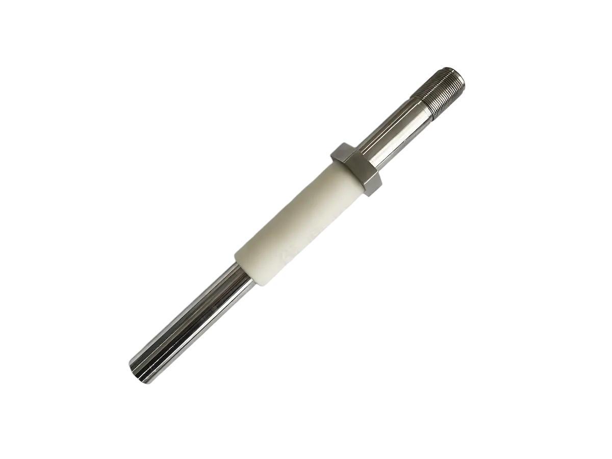
The igniter supplies sufficient energy to light the main fuel during cold start or re‑lighting. Modern burners predominantly use high‑energy igniters.
Construction:
Ignition rod (semiconductor ceramic or metal probe)
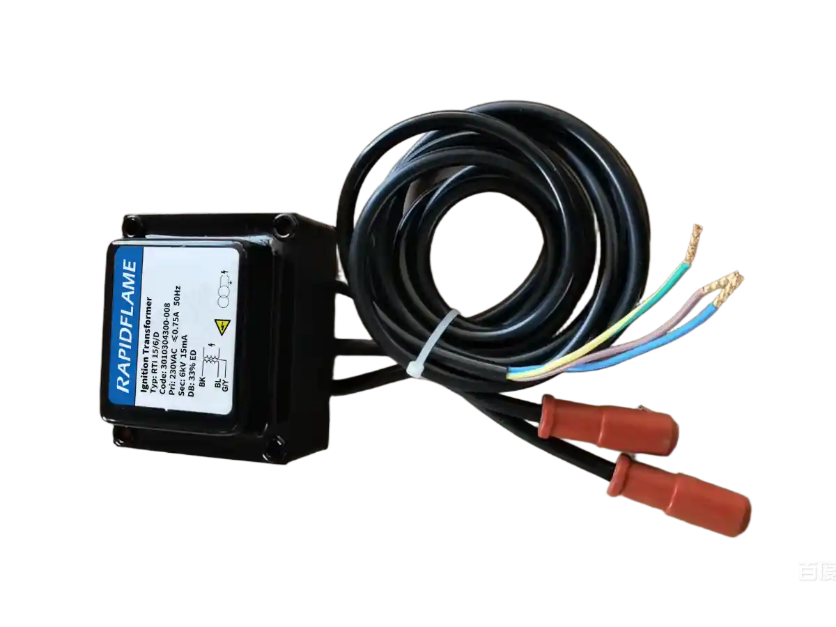
High‑energy ignition transformer (output typically 2000–4000 V, spark energy 1–20 J)
Retraction mechanism (protects from high temperature; retracts automatically after ignition)
Operation – The transformer generates a high voltage, creating a plasma channel on the semiconductor surface. Local temperatures exceed 2000 °C, directly igniting the fuel‑air mixture.
Key parameters – Spark frequency (typical 6–12 Hz), temperature resistance (flame side up to 1300 °C), insulation resistance (≥100 MΩ).
Safety notes – Pre‑purge is mandatory before ignition (typically 5 furnace volumes). Ignition failure must trigger a fuel cut‑off interlock.
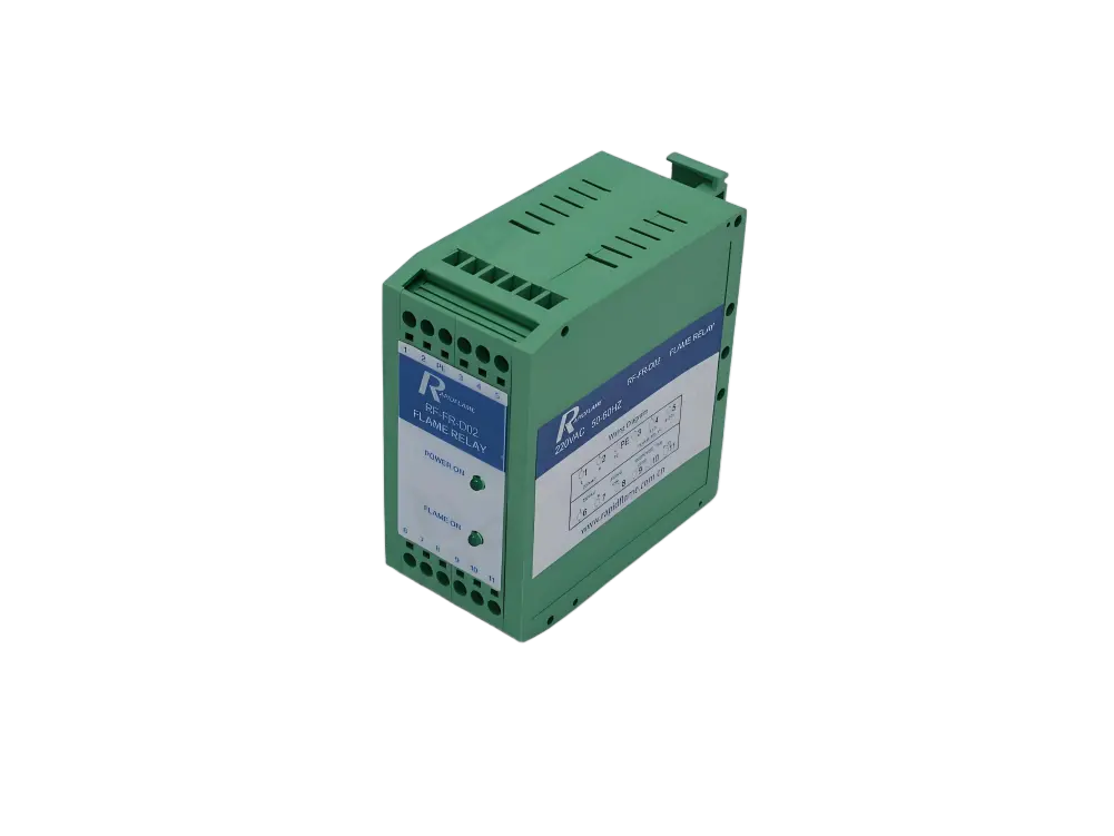
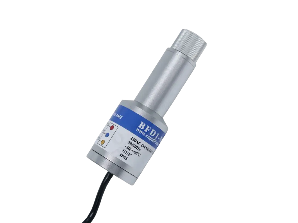
Flame detectors act as the “eyes” of the burner safety system, confirming whether a flame exists. Based on sensing principles, three main types are used:
| Type | Sensitive Band | Response Time | Immunity to Interference | Typical Application |
|---|---|---|---|---|
| UV (Ultraviolet) | 185–260 nm | Fast (<1 ms) | Avoids sunlight and thermal radiation; sensitive to welding arcs | Multi‑fuel boilers |
| IR (Infrared) | 4.4–4.6 µm (CO₂ emission peak) | 2–5 ms | Requires filtering of non‑flame hot bodies; dual‑wavelength versions available | Gas turbines |
| Flame Rod (Ionization) | Based on flame conductivity | Continuous analog | Works only with conductive flames (gas/oil); simple construction | Small to medium burners |
Installation & maintenance:
Keep the sight window clean; use cooling air to protect the sensor from overheating.
Perform periodic simulated flame tests (using a dedicated flashlight or circuit).
UV tube lifetime ≈10,000 h; flame rods tend to accumulate carbon.
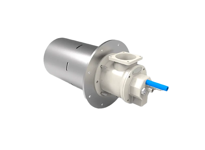
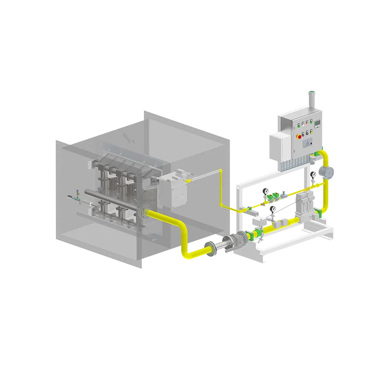
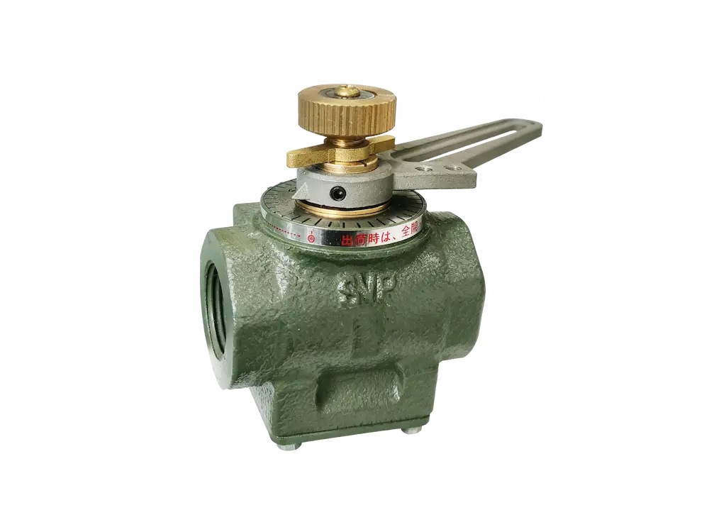
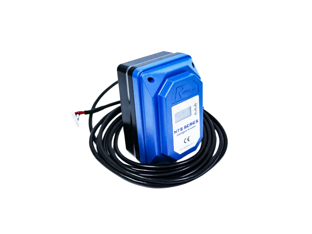
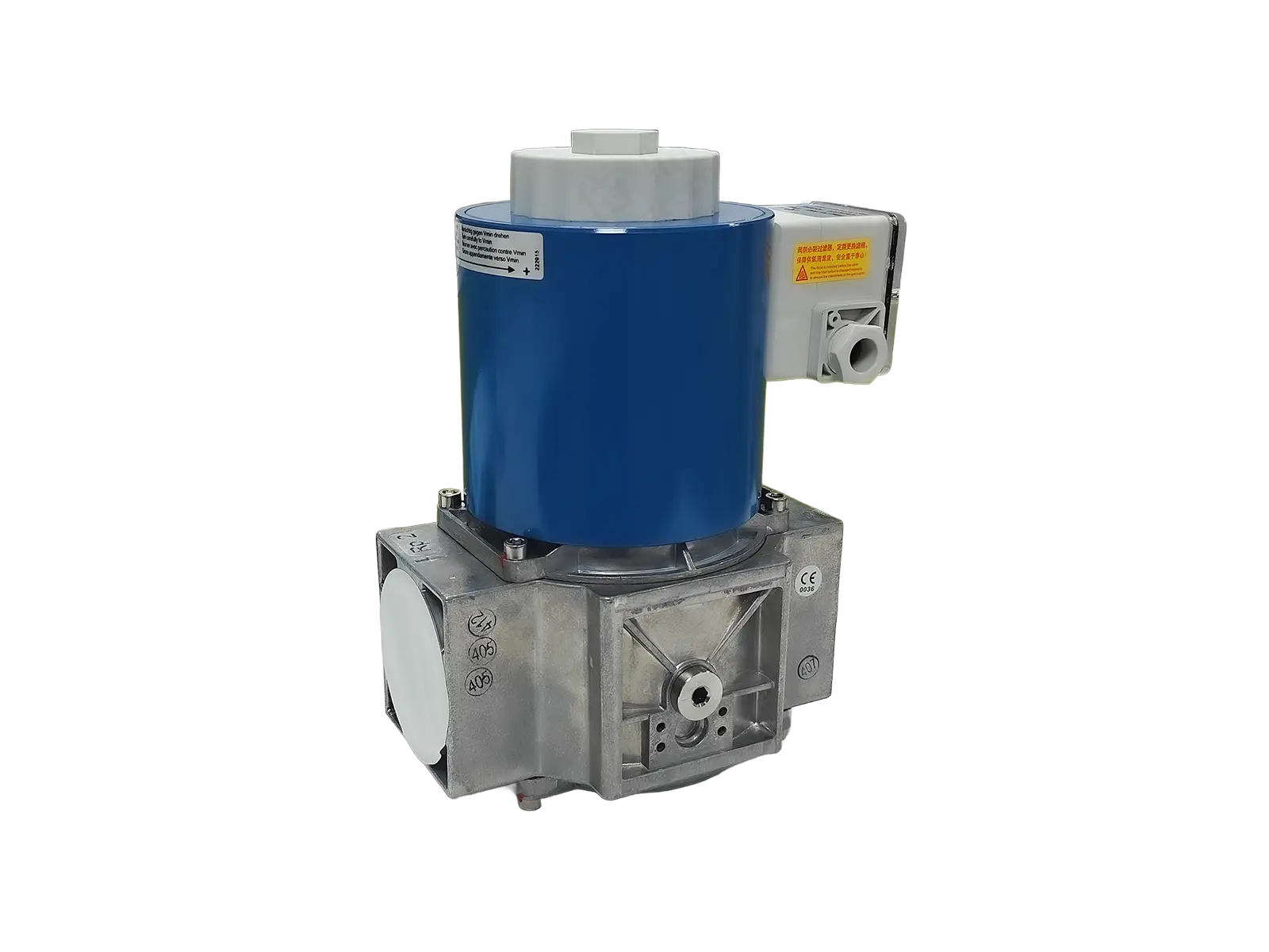
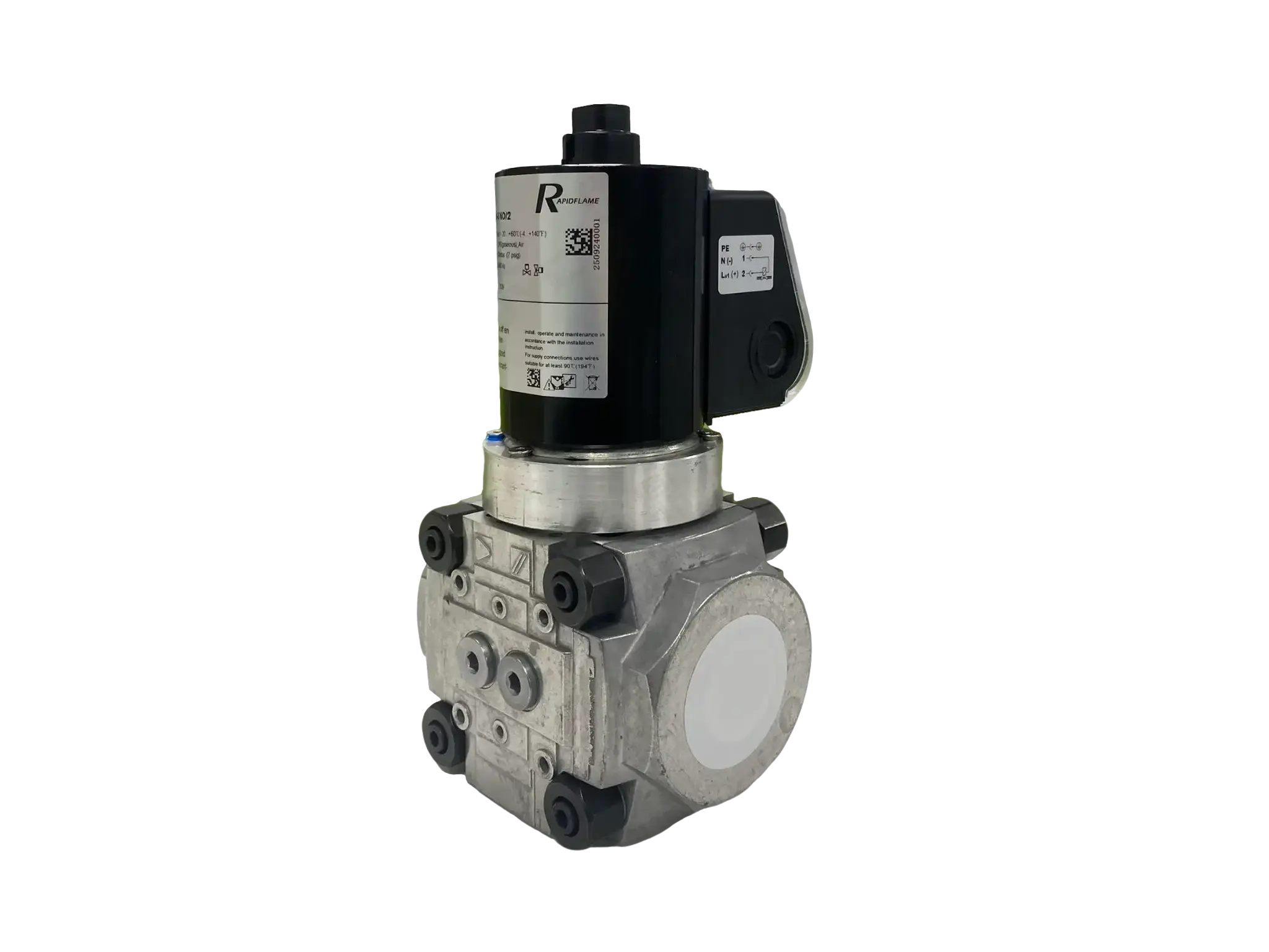
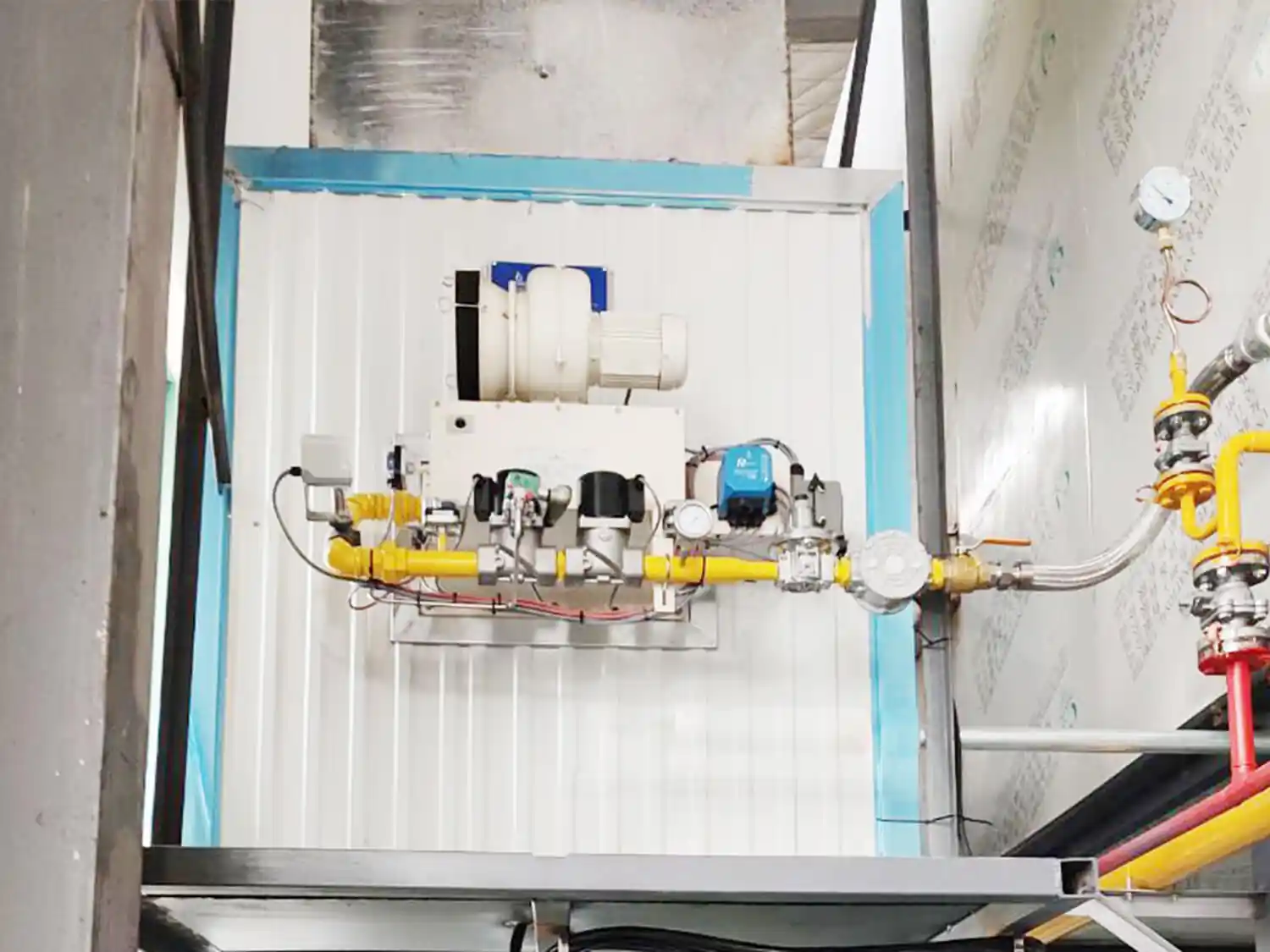
The damper actuator controls the combustion air flow rate, working together with the fuel metering device to maintain the optimal air‑to‑fuel ratio. Modern burners use electric modulating actuators.
Construction – Servo motor, reduction gear train, feedback potentiometer (or encoder), limit switches, and linkage mechanism.
Control modes:
Open‑loop position control – Follows a pre‑programmed curve linked to the fuel valve.
Closed‑loop control – Receives a trim signal from an oxygen analyzer (O₂%) to dynamically adjust the damper opening.
Performance parameters:
Travel time (e.g., 10–60 s for 0–90°)
Torque (typically 3–20 N·m, depending on damper size and pressure)
Repeatability (≤0.5°)
Fault diagnosis – Jittering feedback signal (worn potentiometer), mechanical jamming (dust or rust), creeping movement (faulty capacitor or unstable power).
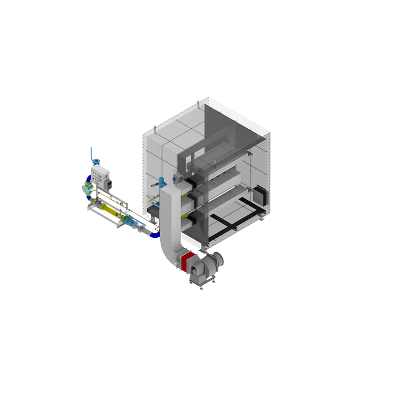
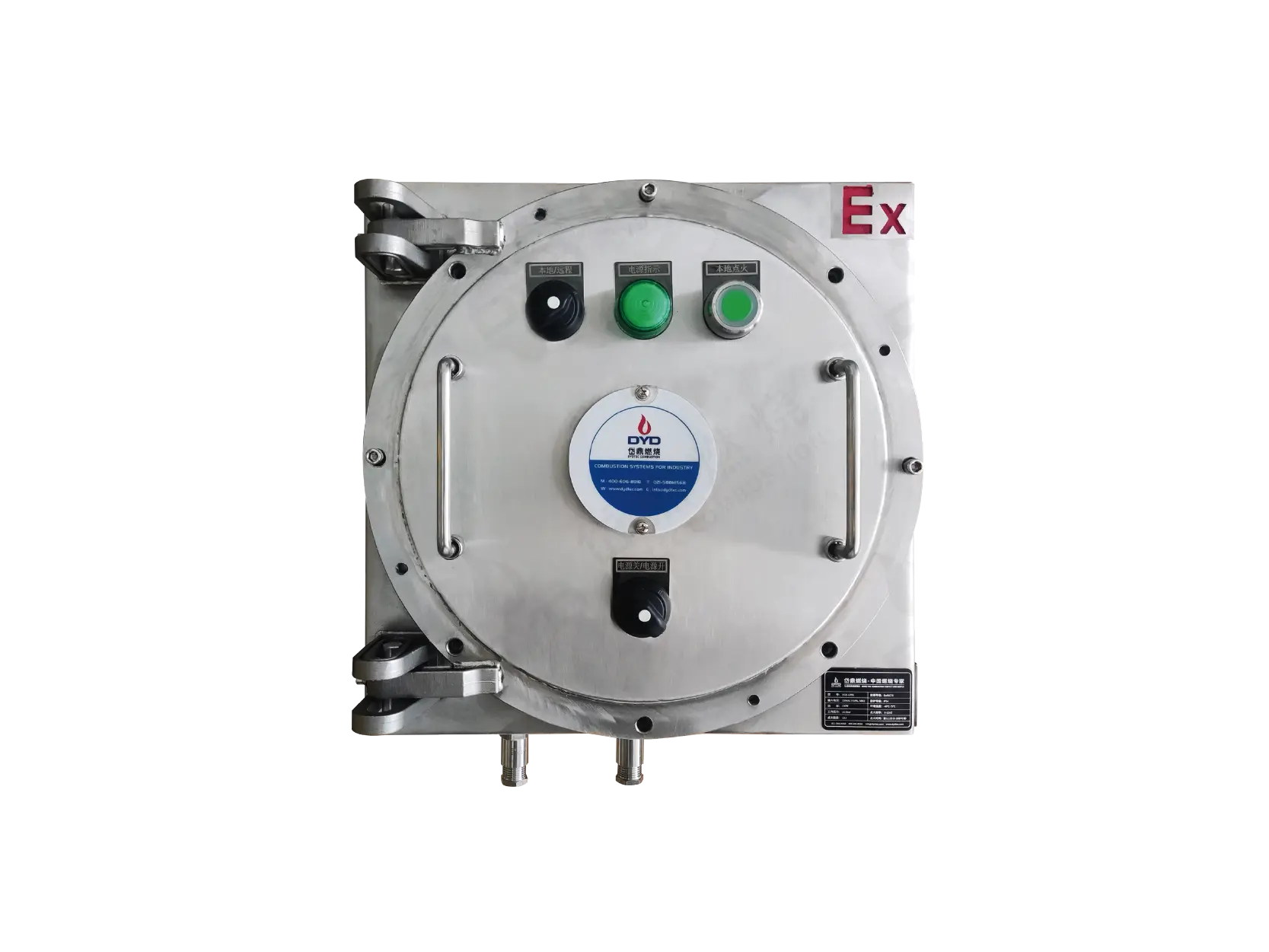
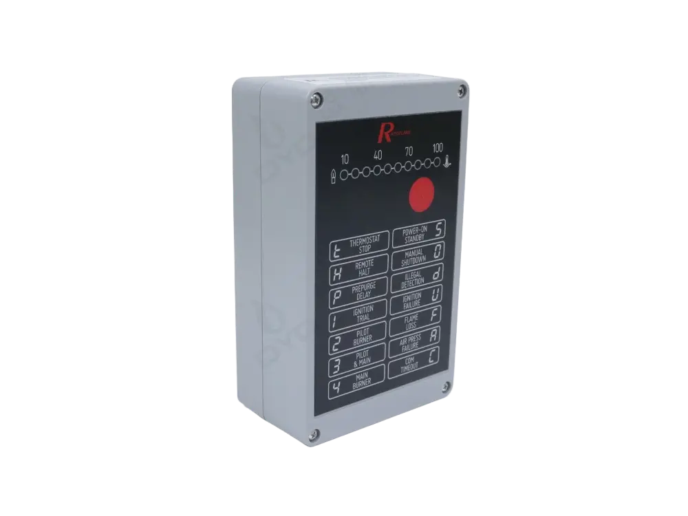
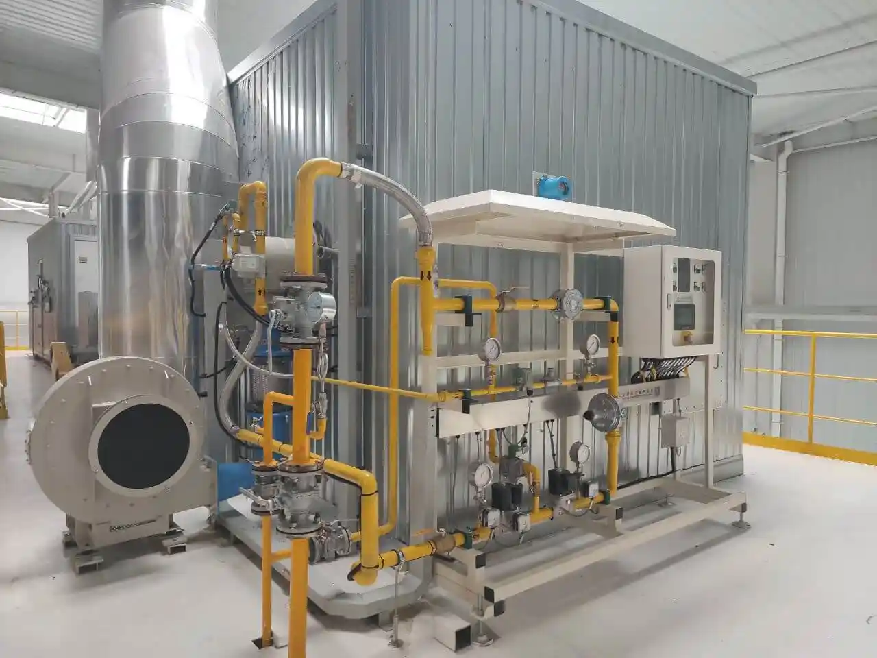
A standard gas burner start‑up logic (example) illustrates how the components work together:
Standby – Controller self‑check; all contacts normal.
Pre‑purge – Damper actuator opens fully; fan runs to purge residual combustibles from the furnace; duration 15–60 s.
Damper return – Actuator moves to ignition opening (typically 15–30%).
Ignition – Igniter sparks; pilot fuel valve opens.
Main flame establishment – Flame detector confirms the pilot flame; main fuel valve opens; main fuel is ignited by the stabilizer.
Flame transfer – Main flame signal is stable; igniter is retracted/de‑energized.
Load modulation – Depending on temperature/pressure setpoint, the damper actuator and fuel modulating valve adjust in unison.
Fuel nozzle – Select atomization type based on fuel (natural gas / light diesel / heavy oil / biogas) and required turndown ratio.
Flame stabilizer – V‑type for high velocity or low‑calorific fuels; annular + swirler for low NOx and wide turndown.
Igniter – High‑energy (>5 J) for large systems; spark‑plug type for small commercial burners.
Flame detector – UV/IR combination for multi‑fuel or UV‑interference environments; flame rod for stable, single‑fuel applications (cost‑effective).
Damper actuator – Ensure compatibility with the burner control system (0–10 V, 4–20 mA, or Modbus).