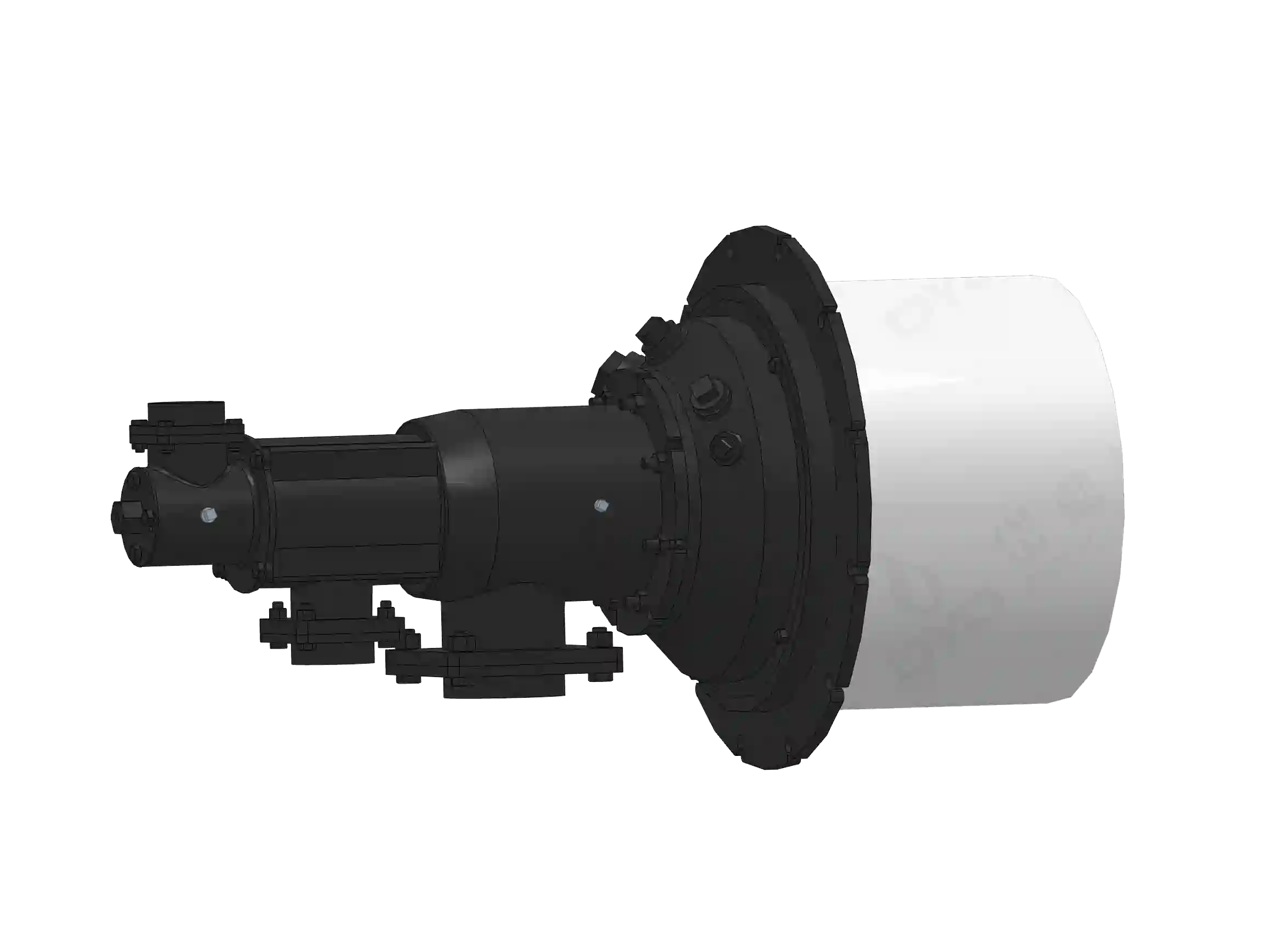
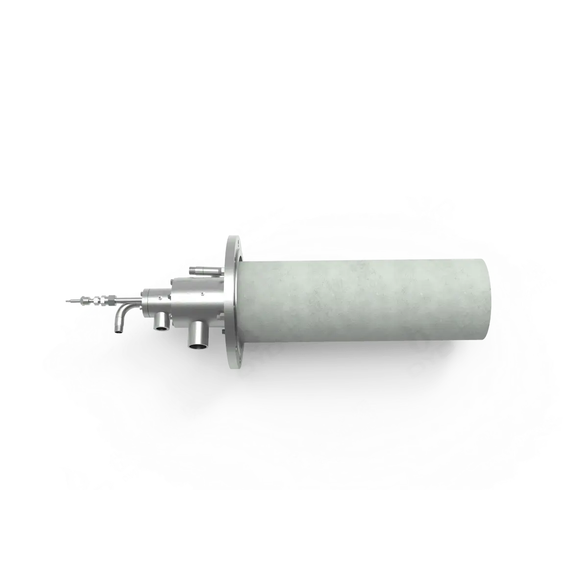
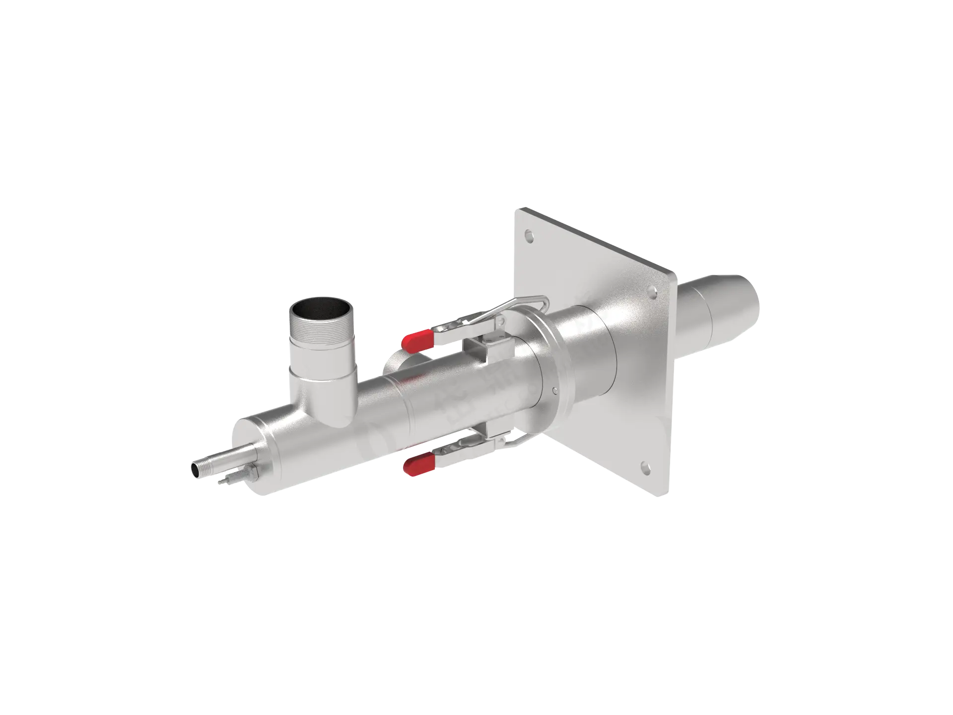
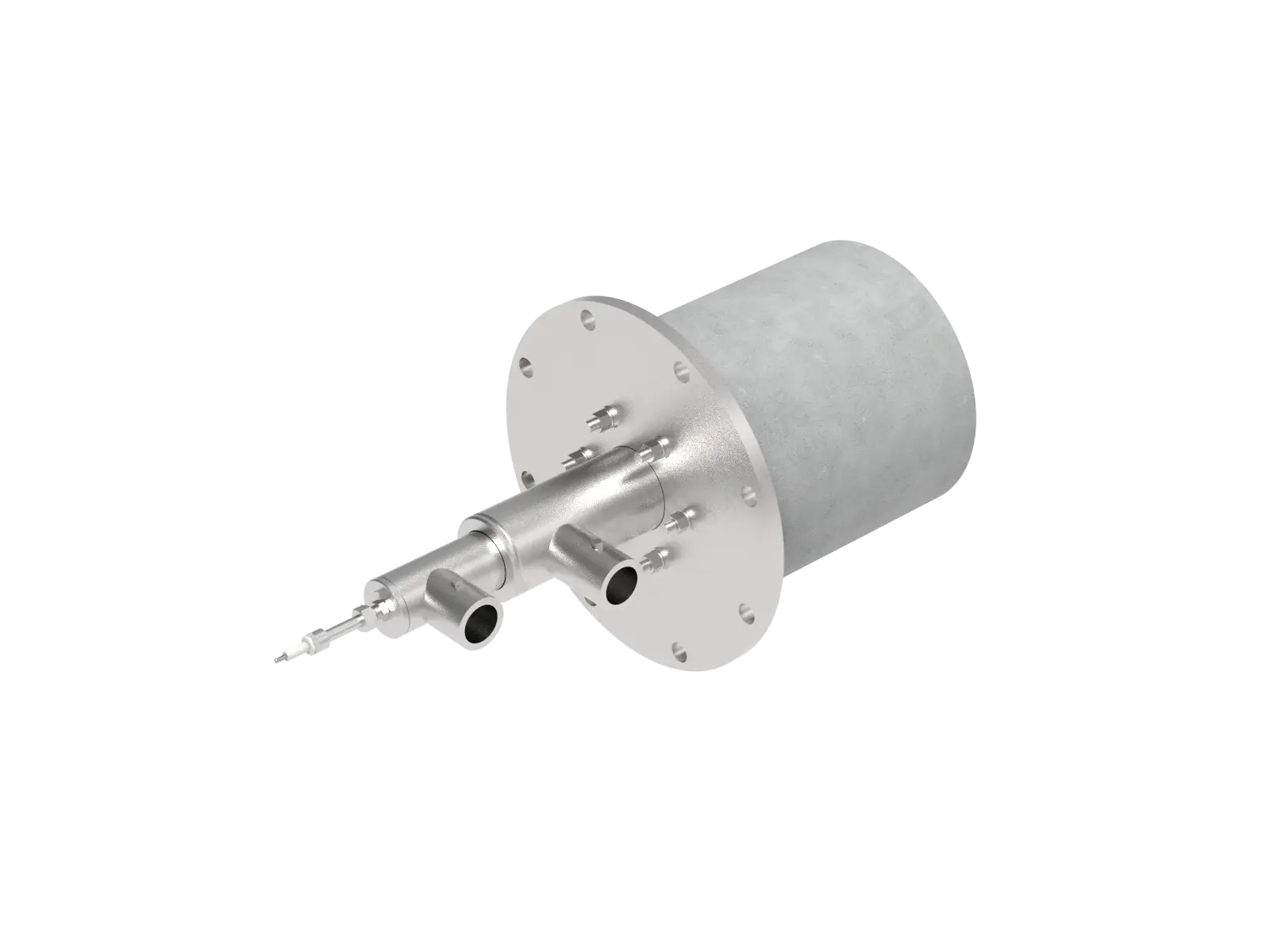
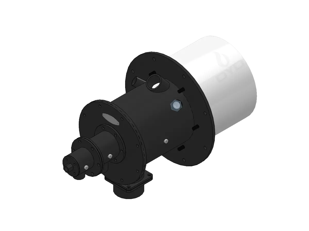
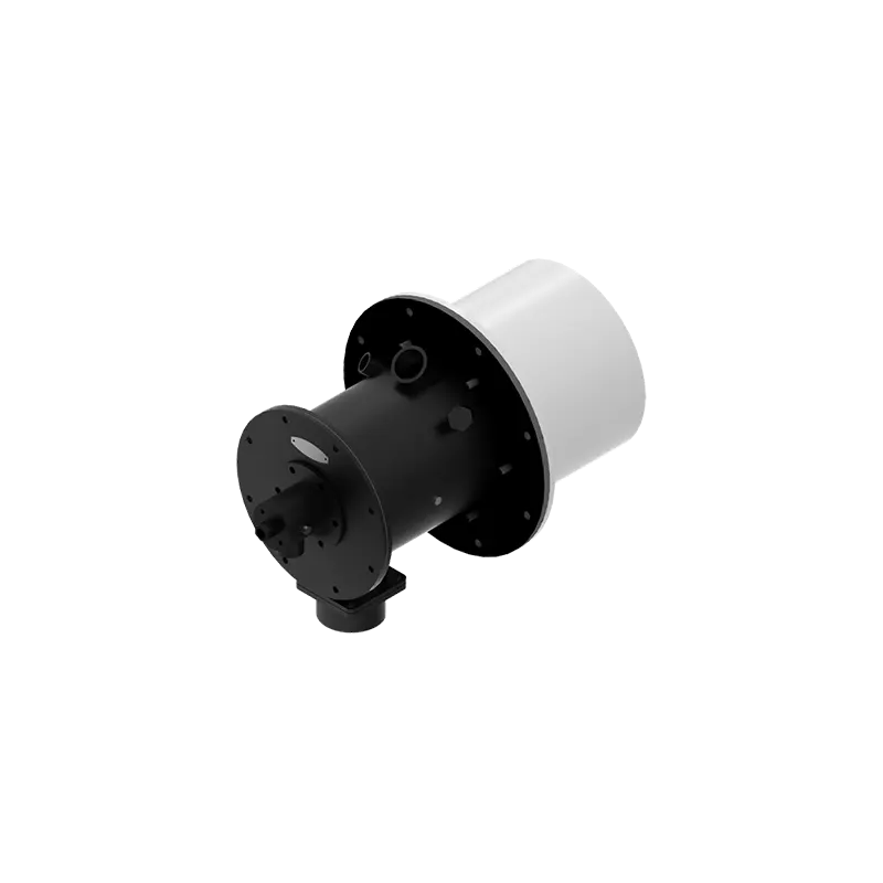
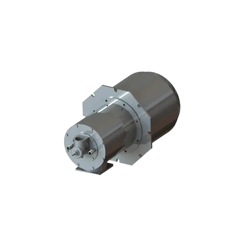
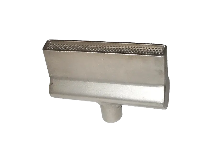
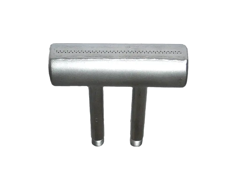
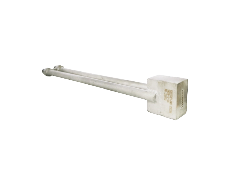
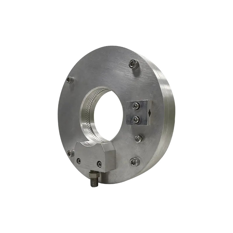
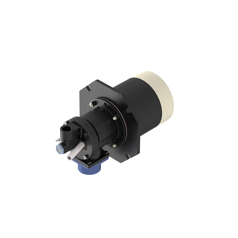
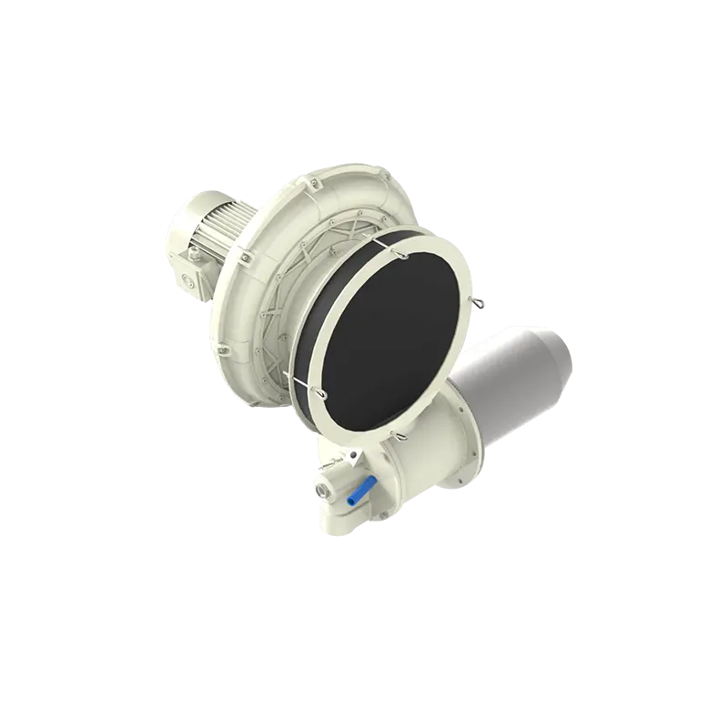
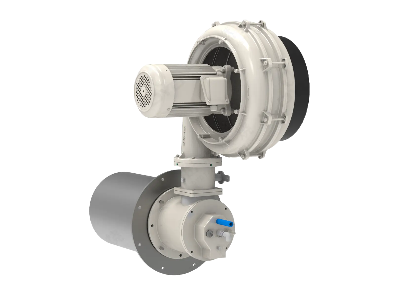
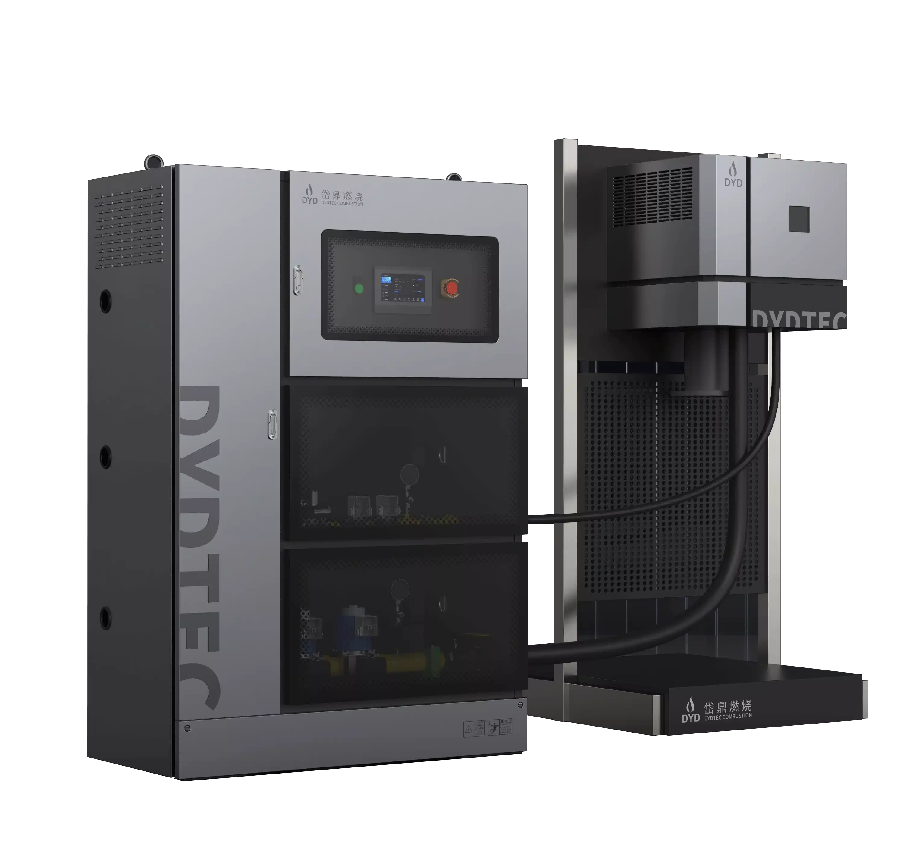
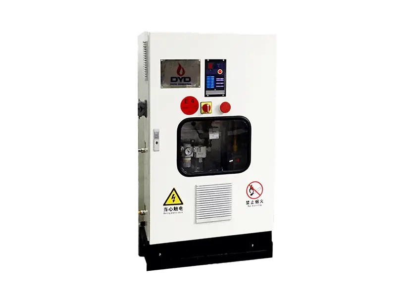
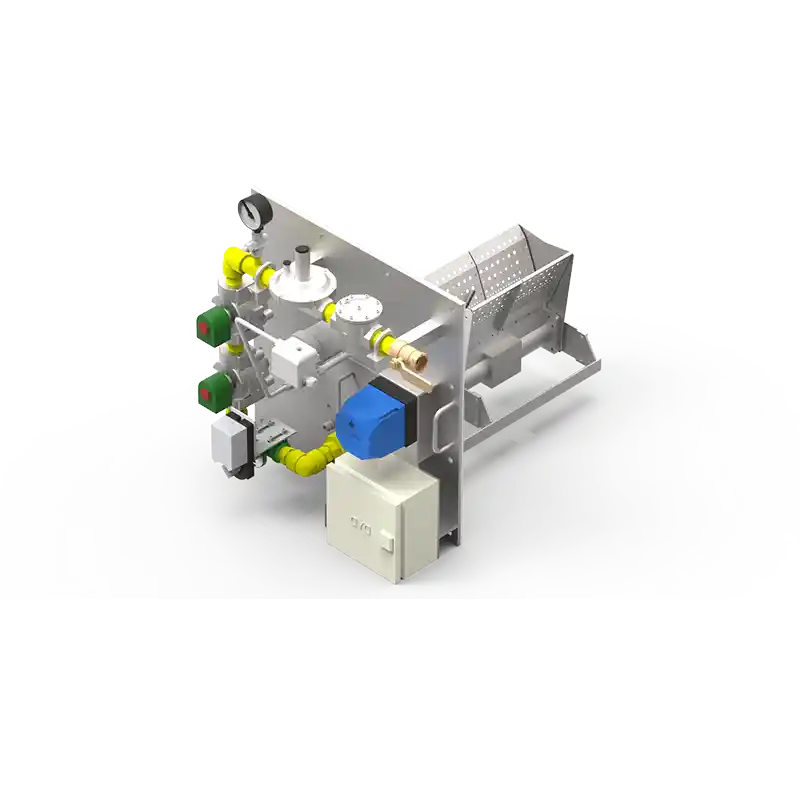
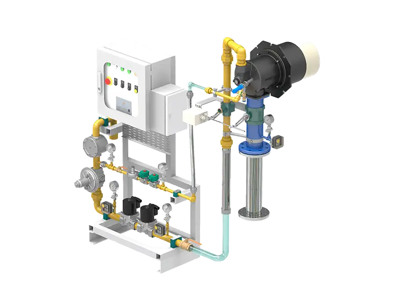
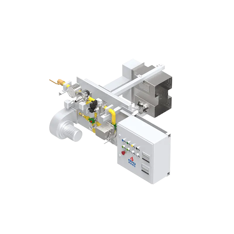
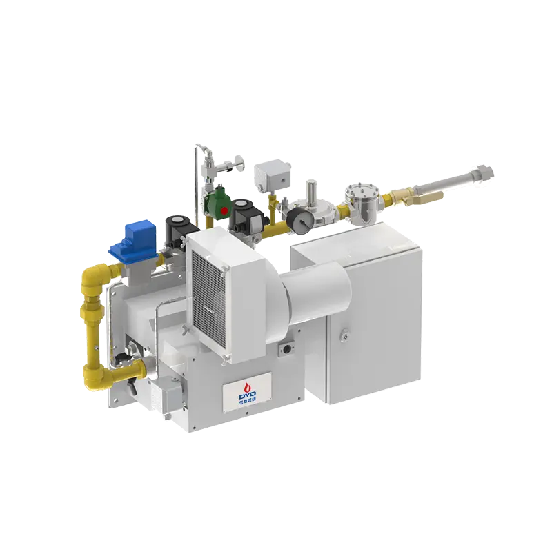
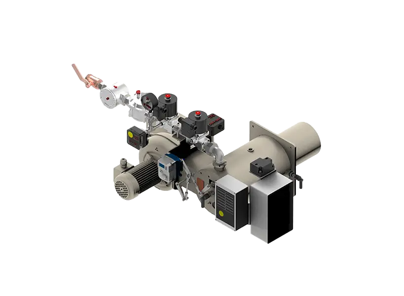
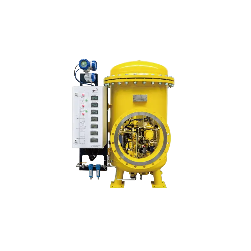
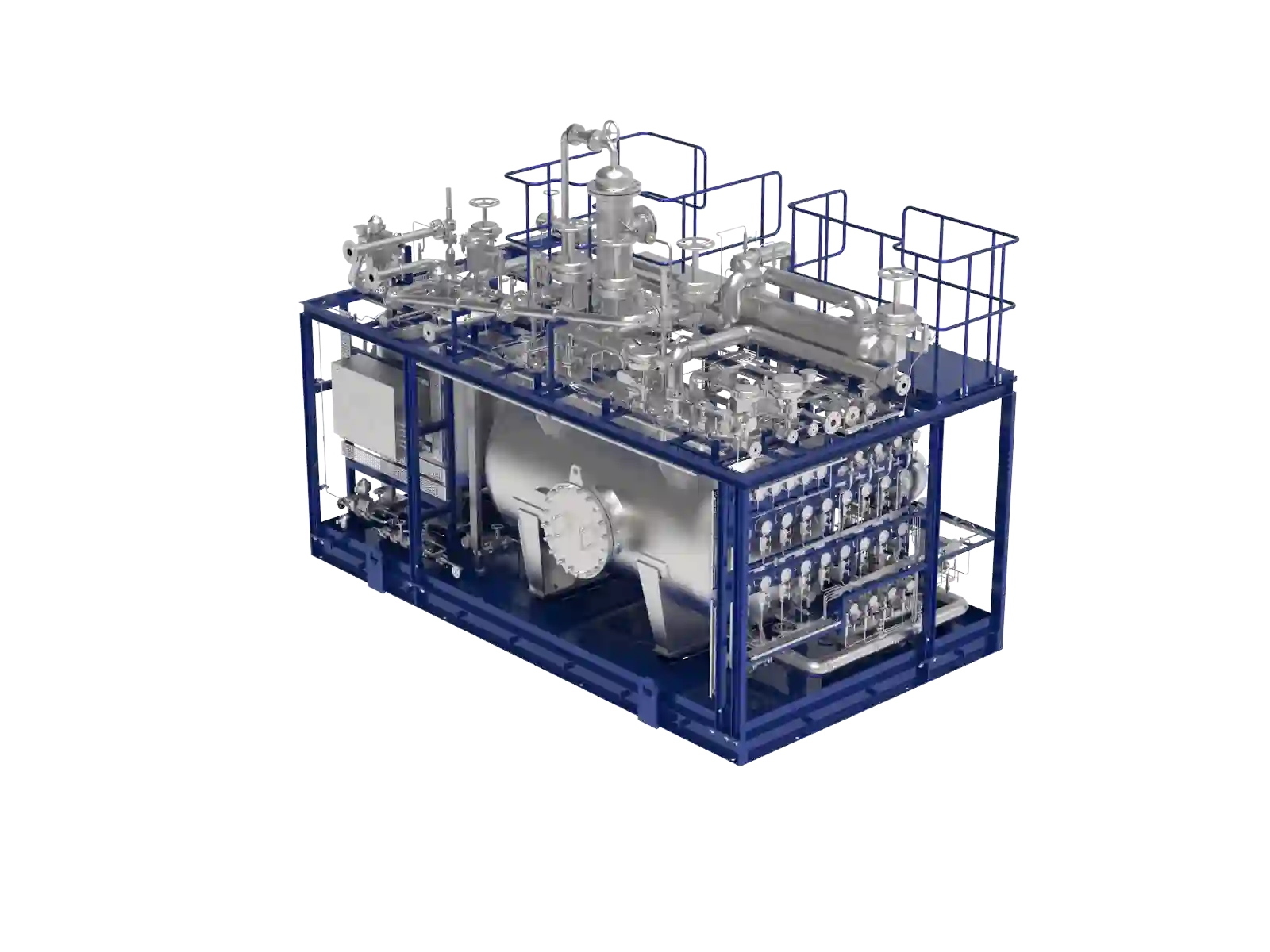
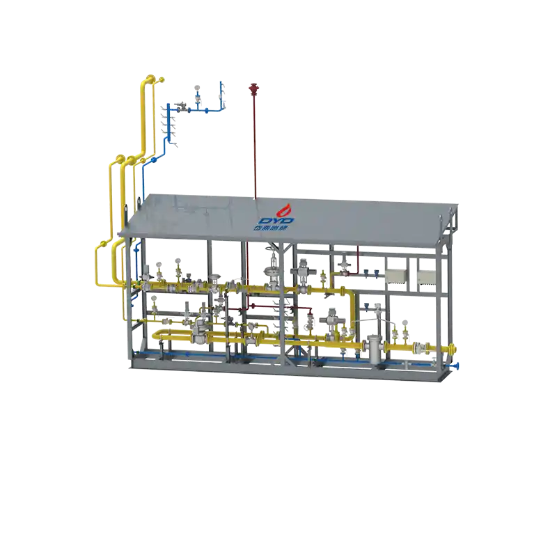
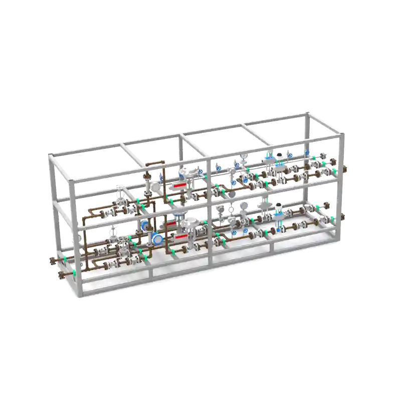
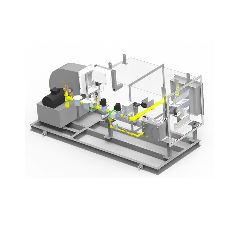
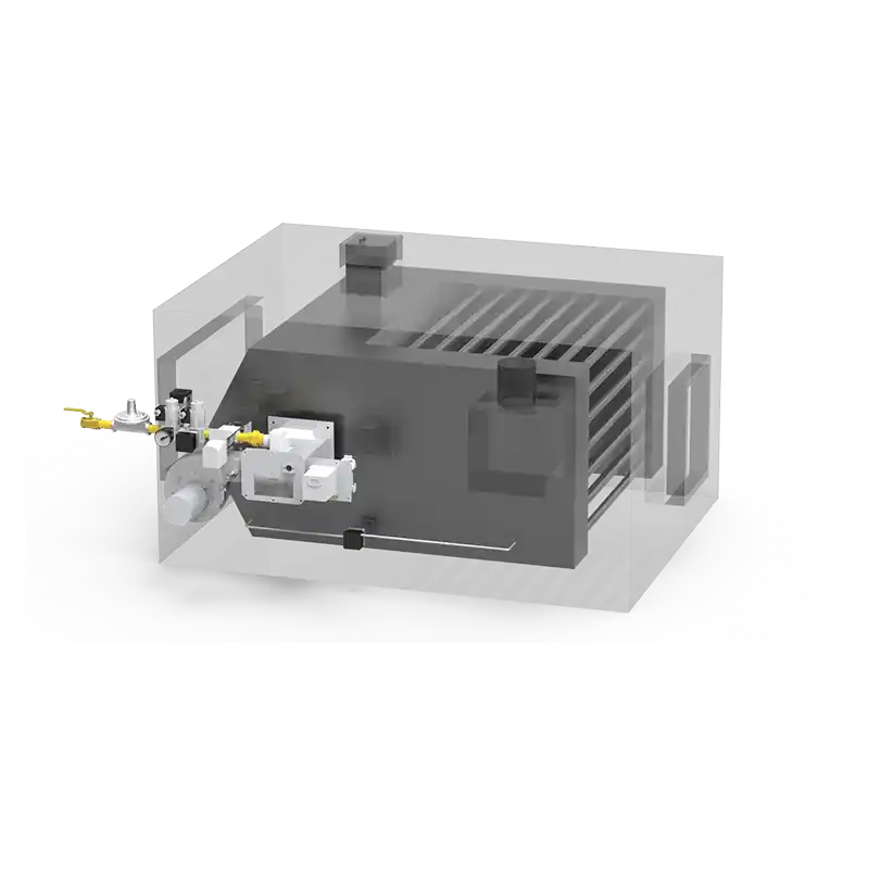
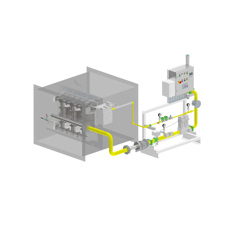
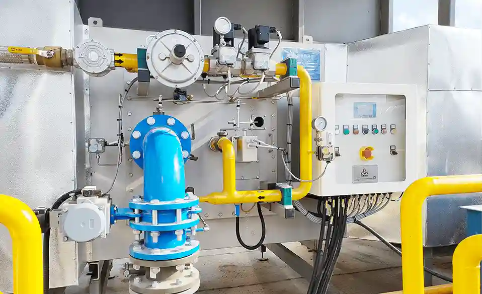
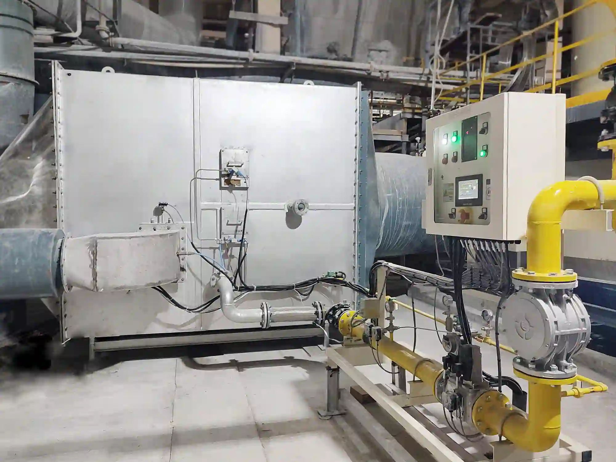
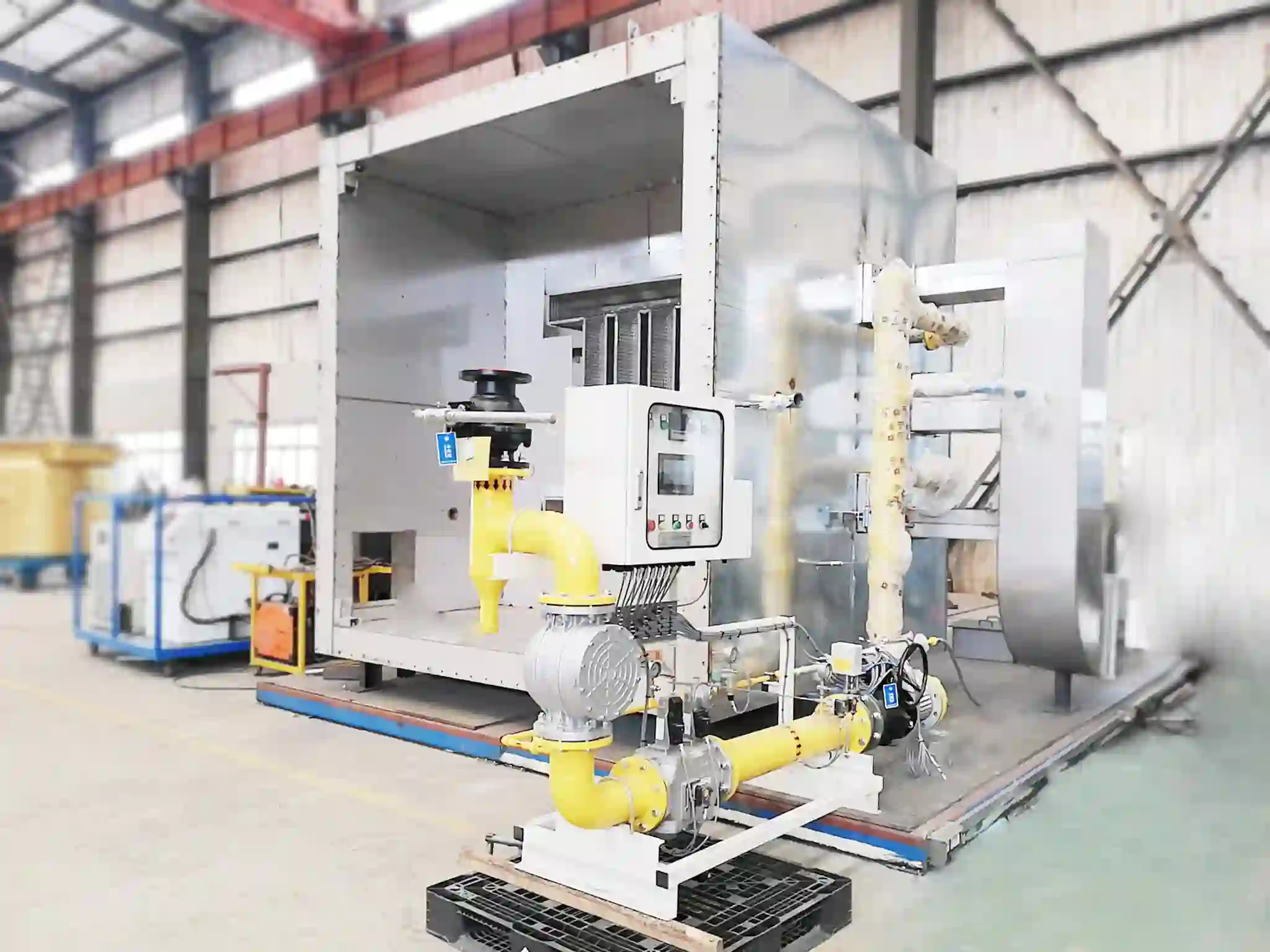
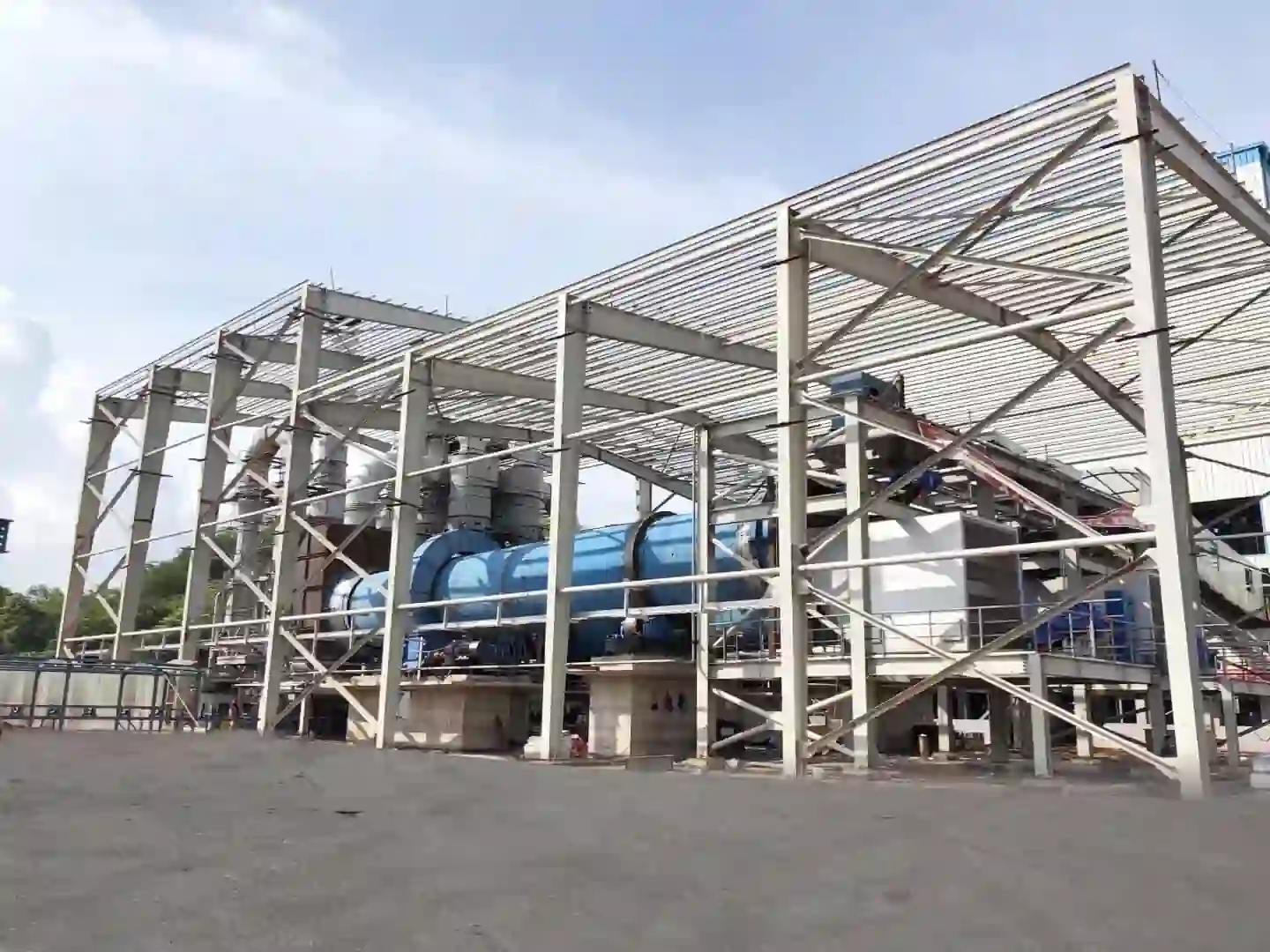
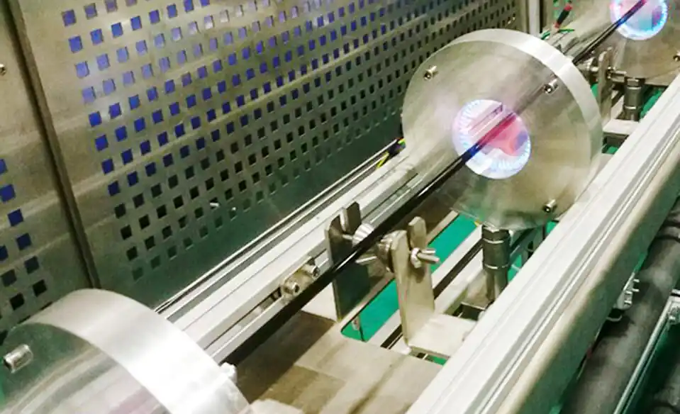
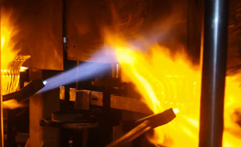
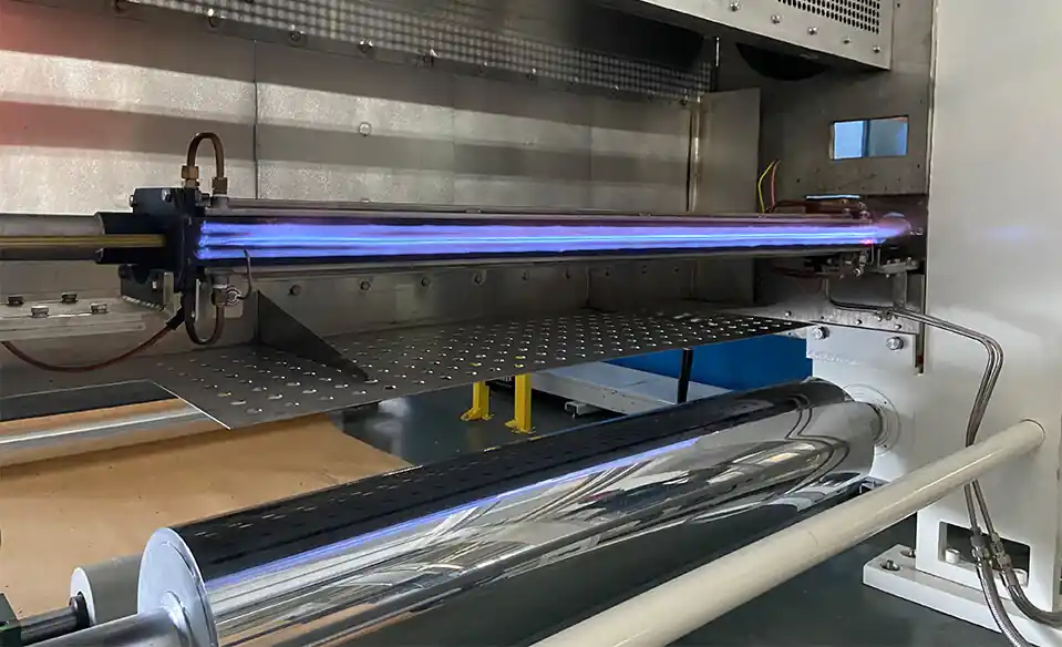
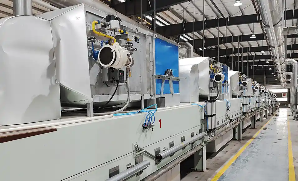
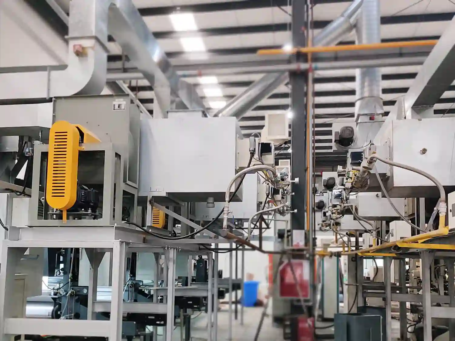
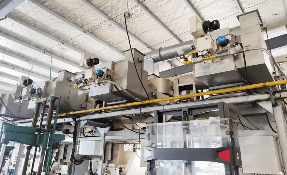
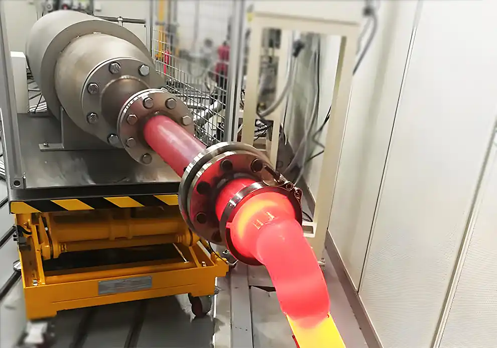
Natural gas burns in an industrial burner through a carefully controlled process in which natural gas mixes with combustion air, is ignited, and releases heat through a stable flame. The primary combustion reaction is the oxidation of methane (CH₄) with oxygen from the air, producing carbon dioxide (CO₂), water vapor (H₂O), and heat. Under stoichiometric conditions, 1 m³ of natural gas requires approximately 9.5–10.5 m³ of air for complete combustion, releasing about 35.9 MJ of energy (lower heating value) per cubic meter.
Modern industrial burners precisely regulate fuel flow, combustion air, ignition, and flame supervision to achieve high combustion efficiency (typically 95–99% on LHV basis), low emissions (CO below 50 ppm, NOx below 30–80 ppm depending on burner design), stable flame performance, and safe operation. The adiabatic flame temperature for natural gas in air is approximately 1,950–2,000°C, though actual furnace temperatures are significantly lower due to heat losses and excess air dilution.
Although the process appears simple, industrial combustion is the result of sophisticated burner engineering and automatic control systems working together to maintain optimal conditions across varying loads, fuel compositions, and environmental conditions.
Natural gas is composed primarily of methane (CH₄) , typically accounting for 85–95% of its composition, depending on the gas source. The remaining constituents include small amounts of ethane (C₂H₆), propane (C₃H₈), butane (C₄H₁₀), nitrogen (N₂), carbon dioxide (CO₂), and trace amounts of other hydrocarbons and inert gases. The exact composition affects the heating value, flame speed, and stoichiometric air requirement.
During combustion, methane reacts with oxygen in the air in an exothermic (heat-releasing) chemical reaction:
CH₄ + 2O₂ → CO₂ + 2H₂O + Heat
For every molecule of methane burned, two molecules of oxygen are consumed, producing one molecule of carbon dioxide and two molecules of water vapor. This reaction releases approximately 802 kJ of heat per mole of methane (or 50.1 MJ per kg of methane). When accounting for the heating of nitrogen from the combustion air (which does not participate chemically but absorbs heat), the practical heat release per unit of fuel is defined by the fuel's lower heating value (LHV) and higher heating value (HHV). For natural gas, LHV is typically 35.9 MJ/Nm³ and HHV is approximately 39.8 MJ/Nm³.
This chemical reaction releases a large amount of thermal energy that can be used for industrial heating processes such as:
Aluminum melting – requiring temperatures of 700–1,100°C
Heat treatment – hardening and tempering in the 800–1,050°C range
Drying – typically 100–400°C for convective drying
Ceramic firing – kiln temperatures from 800–1,400°C
Glass manufacturing – melting furnaces at 1,400–1,600°C
Steel reheating – billet heating to 1,100–1,250°C
Incineration – waste destruction at 850–1,200°C
Thermal oxidizers (RTO) – VOC abatement at 760–900°C
The objective is to convert as much of the fuel's chemical energy as possible into useful heat while minimizing emissions and fuel losses. In practice, combustion efficiency is determined by how completely the fuel is oxidized and how much of the released heat is effectively transferred to the process rather than lost through the exhaust or furnace walls.
Industrial burner operation can be divided into five key stages, each of which must function correctly for the overall combustion process to be safe, stable, and efficient.
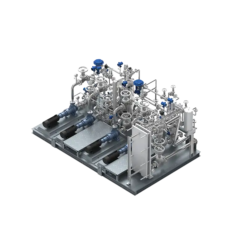
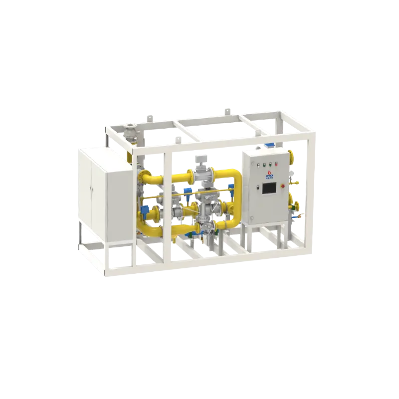
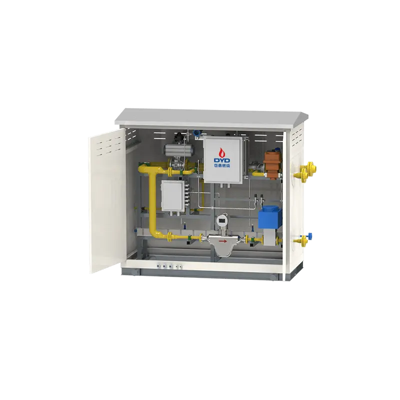
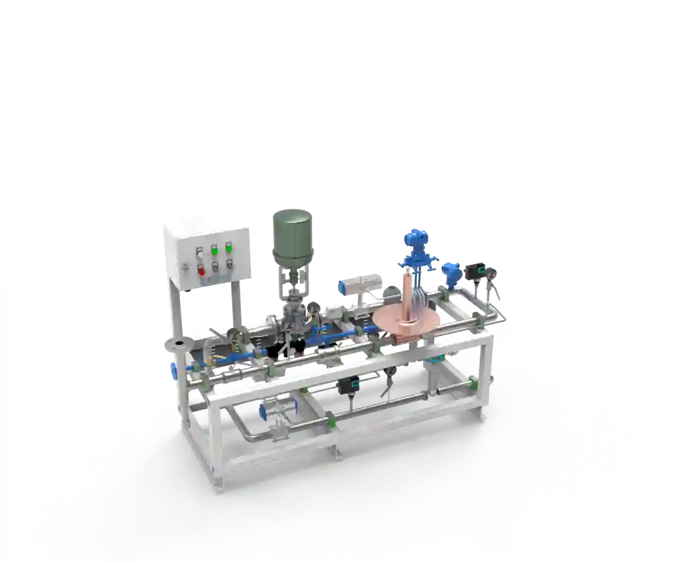
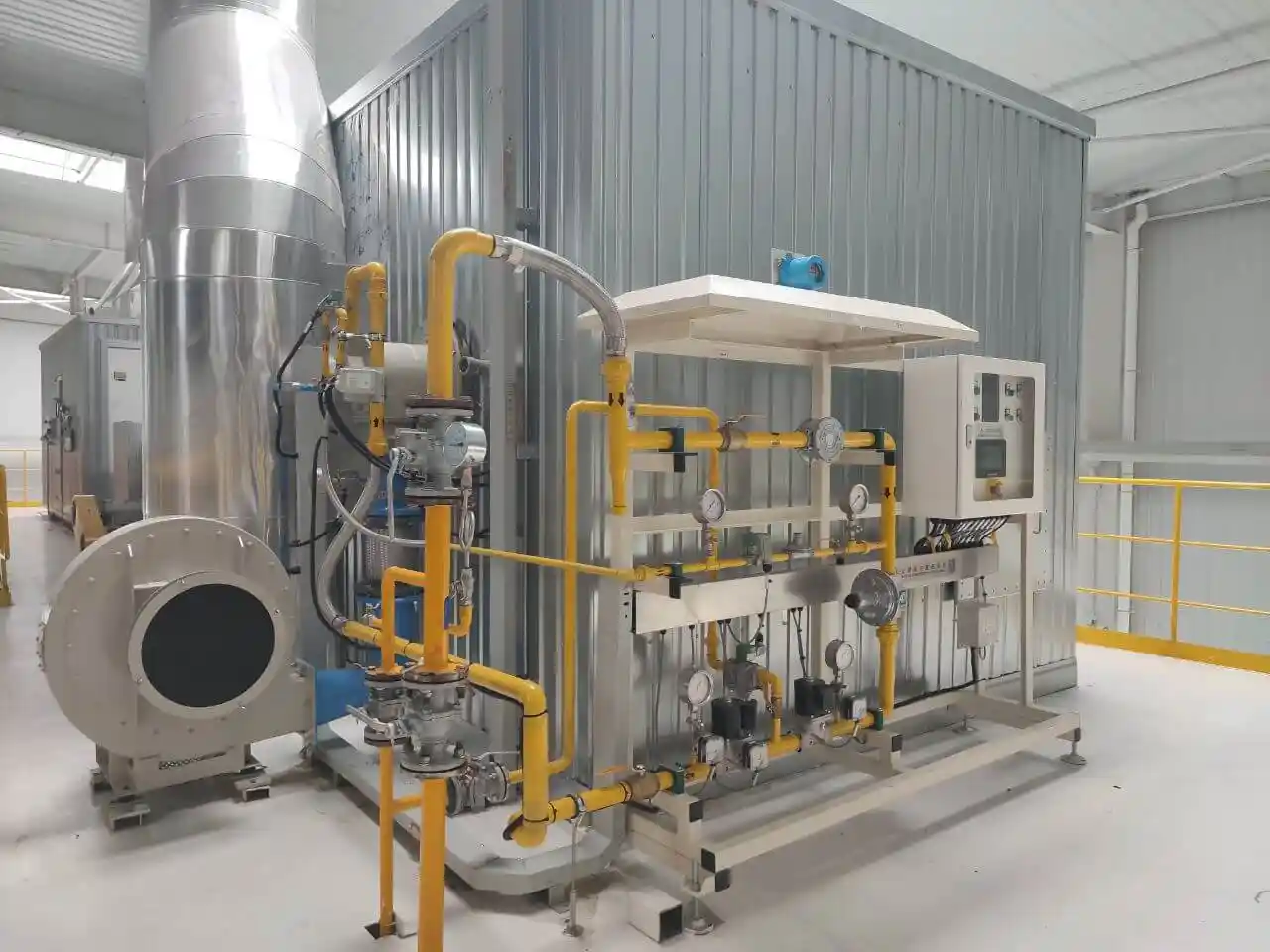
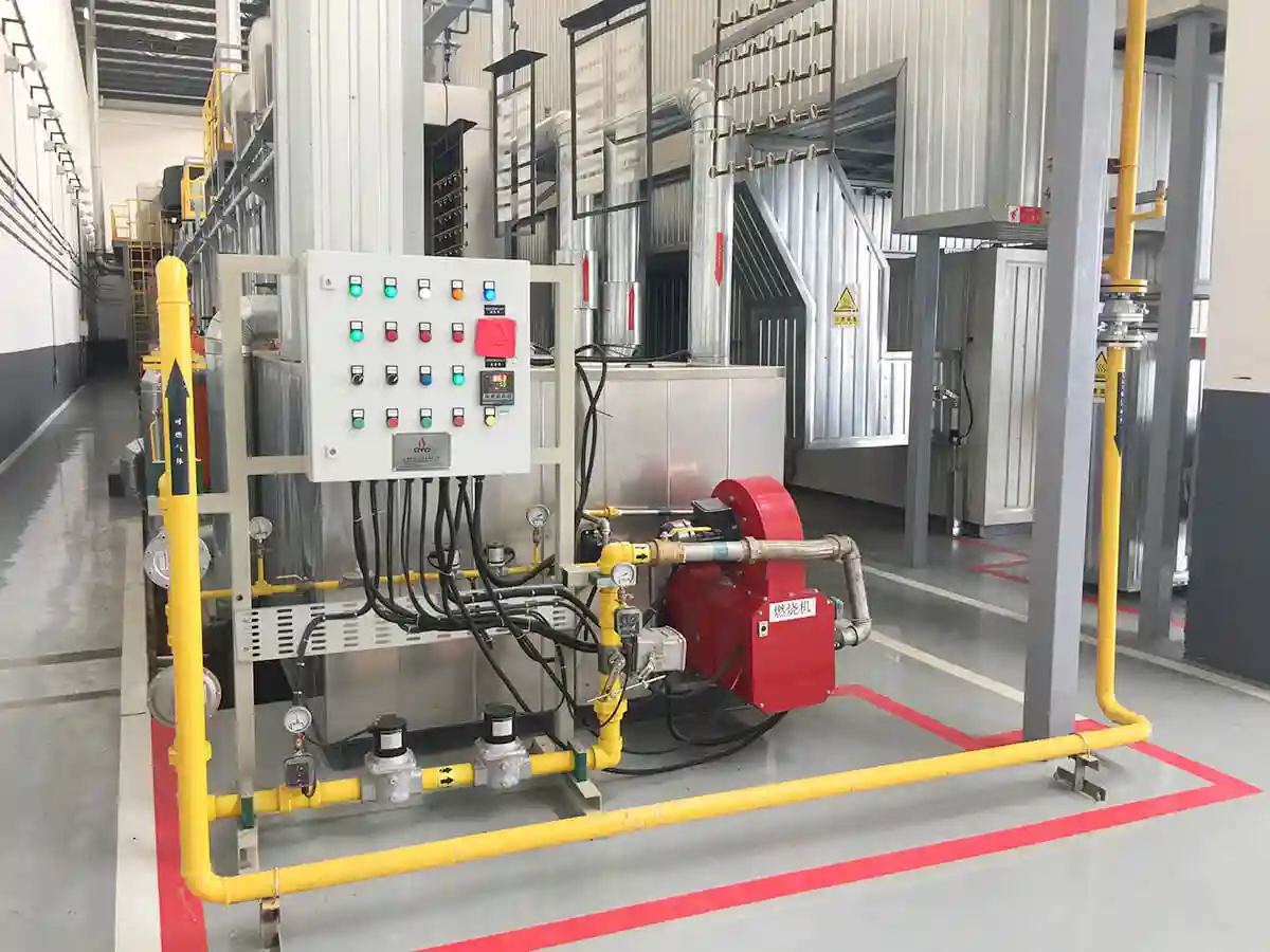
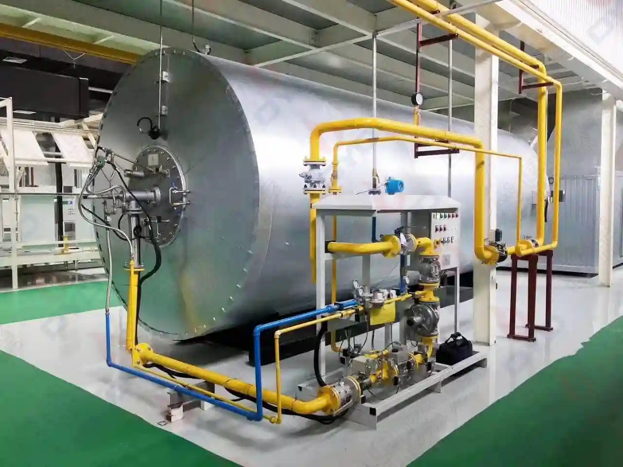
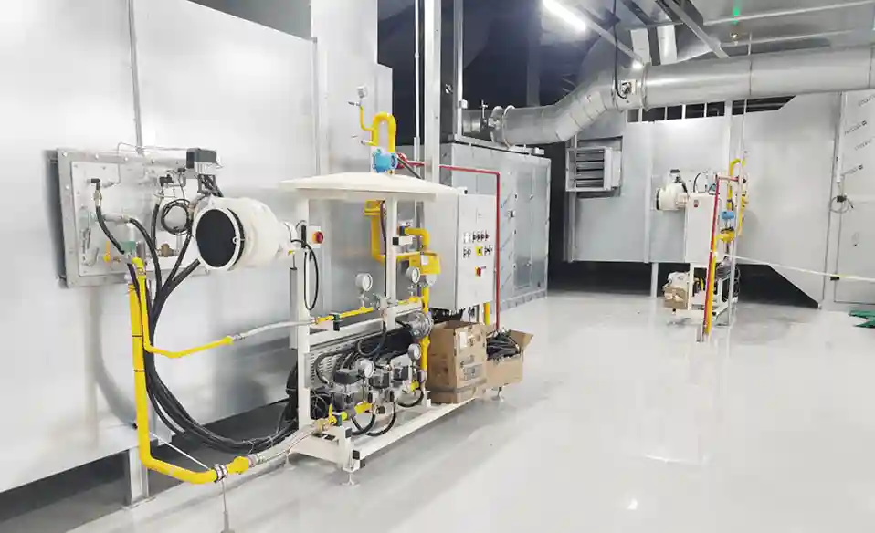
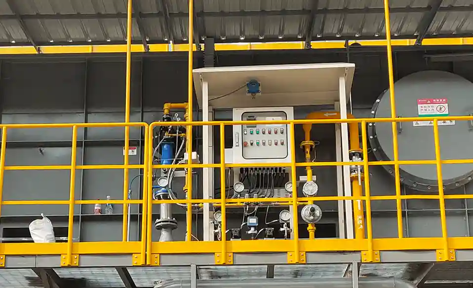
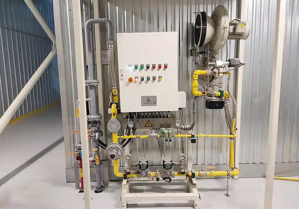
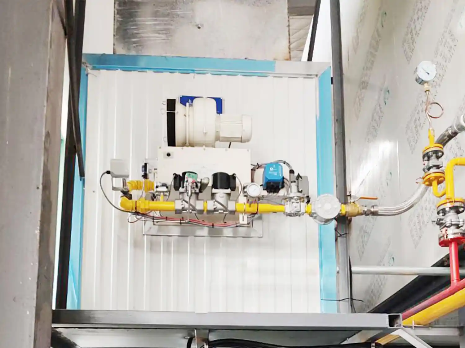
The combustion process begins with the fuel supply system. Before reaching the burner, natural gas typically passes through a series of components that condition and control the fuel:
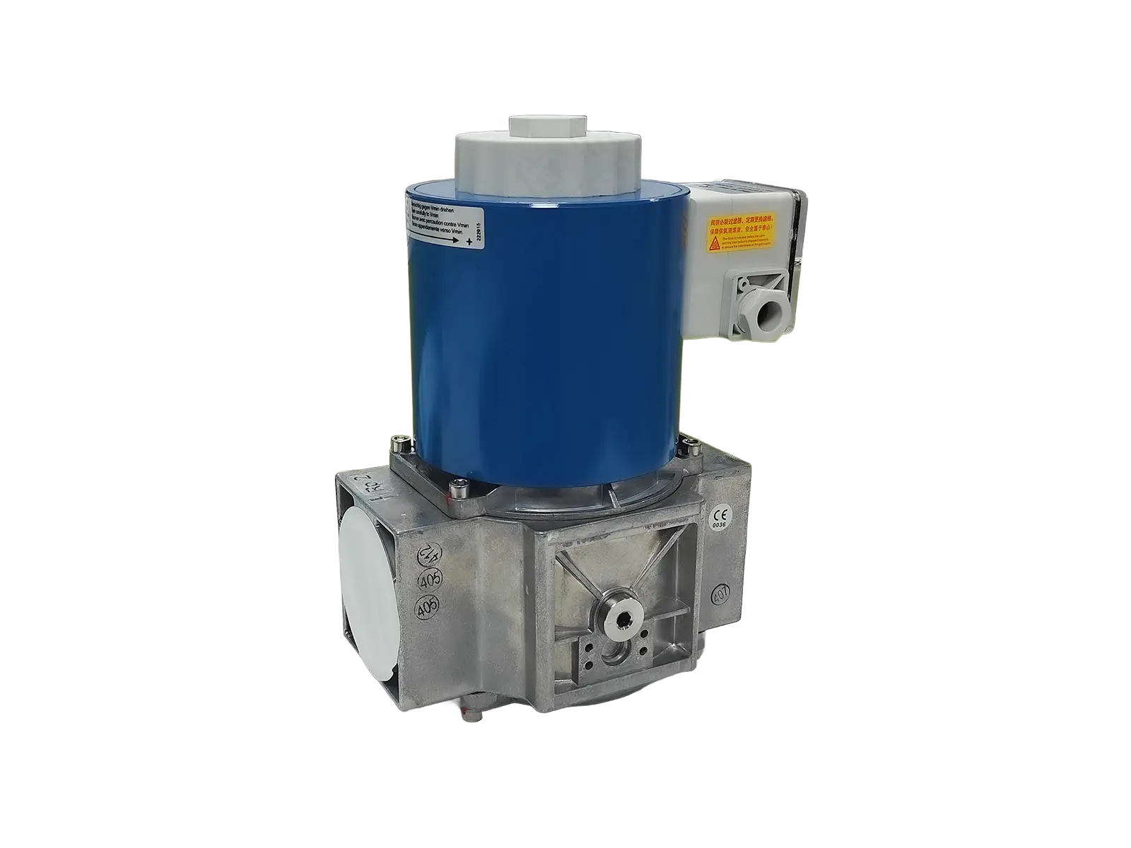
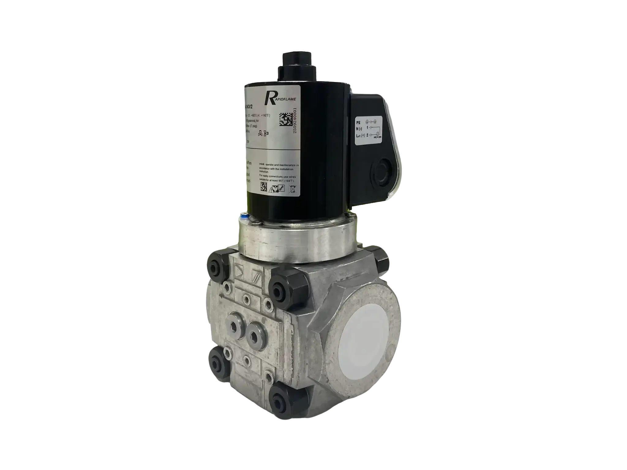
Gas shutoff valves – manual and automatic valves for isolation and emergency shut-off.
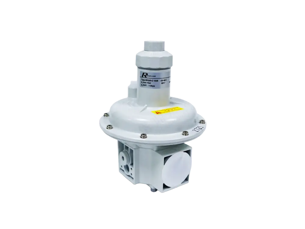
Pressure regulators – maintain a stable outlet pressure (typically 20–50 mbar for low-pressure systems, or 1–5 bar for medium-pressure burners) despite upstream supply variations.
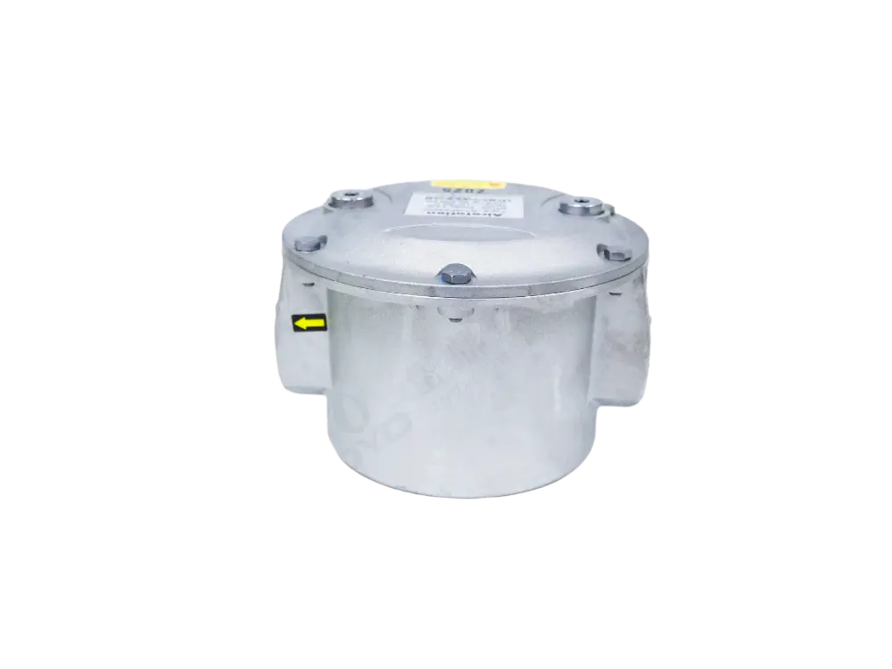
Gas filters – remove particulates and debris that could clog valves or burner nozzles.
Safety valves – double-block-and-bleed valve trains that provide redundant shut-off and leak-tight closure.
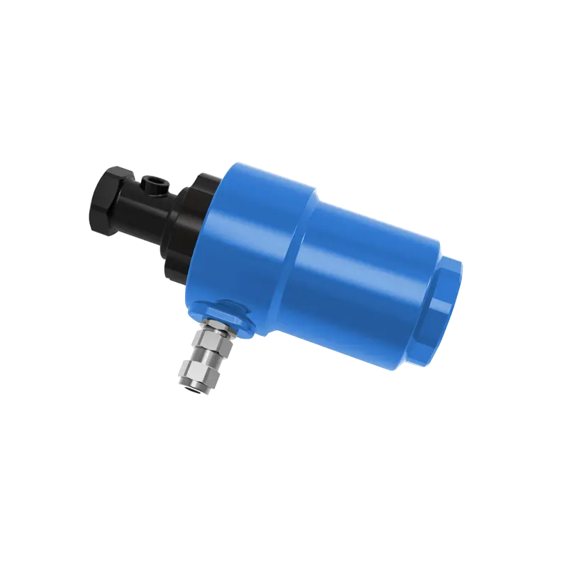
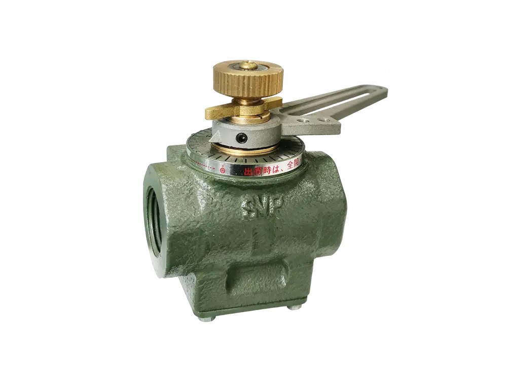
Flow control valves – modulating valves that adjust fuel flow according to the firing rate demand signal from the combustion controller.
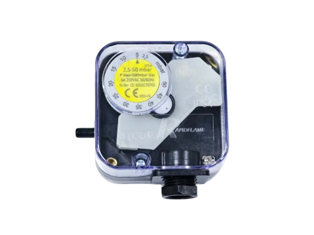
Pressure switches – low-pressure and high-pressure switches that trip the system if gas pressure falls outside the safe operating range.
These components ensure that the burner receives clean gas at the correct pressure and flow rate. Stable gas pressure is essential for maintaining consistent combustion—a pressure drop of 10% can reduce fuel flow by approximately 5% (for a fixed orifice), which would lean out the mixture and risk flame instability.
Natural gas cannot burn without oxygen. The combustion air supply system delivers the oxygen required for the reaction, in the correct quantity and at the right pressure.
Industrial burners use combustion air supplied by:
Combustion blowers – centrifugal or axial fans sized to deliver the required air volume at the furnace backpressure (typically 20–100 mbar).
Forced-draft fans – push air into the burner and furnace, overcoming resistance from dampers, ducts, and furnace pressure.
Air dampers – butterfly or guillotine dampers that modulate airflow under servo control.
Variable frequency drives (VFDs) – adjust fan speed to match air demand, reducing electrical consumption and providing smoother air control compared to damper throttling.
The air system provides the oxygen required for combustion while maintaining the proper air-to-fuel ratio. For natural gas, the stoichiometric air requirement is approximately 9.5–10.5 Nm³ of air per Nm³ of gas. Modern burners automatically adjust airflow according to firing demand using a ratio control system that coordinates the air damper or fan speed with the gas valve position.
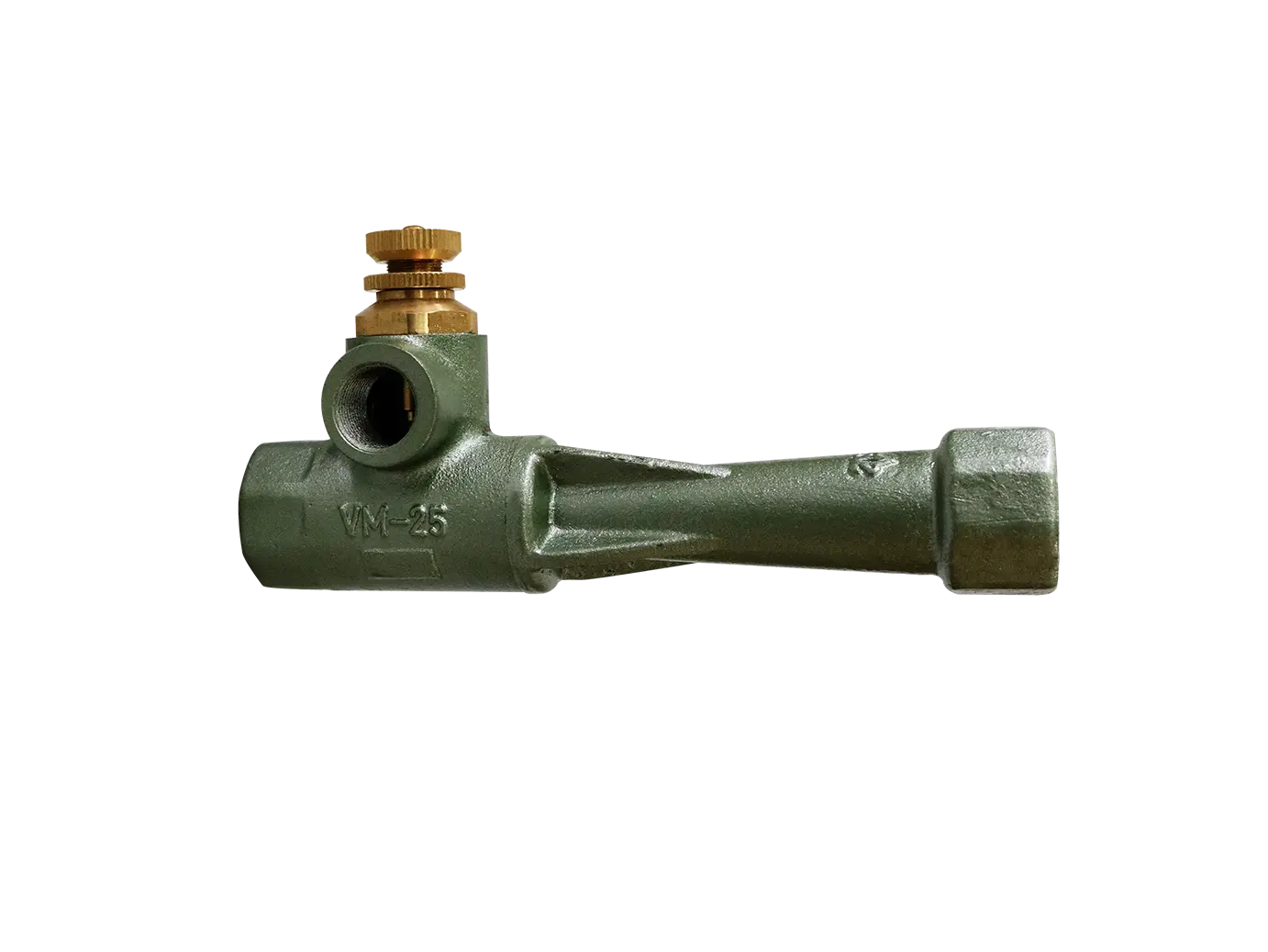
Inside the burner head, natural gas mixes with combustion air. This is one of the most critical stages of the combustion process because the completeness and stability of combustion depend on how intimately and uniformly the fuel and air are combined.
Good mixing provides:
Stable flames – the flame remains anchored and does not pulsate or lift off.
Complete combustion – all fuel molecules encounter sufficient oxygen, minimising CO and soot.
High efficiency – excess air can be kept low (5–15%) because mixing is effective.
Low carbon monoxide (CO) – typically below 50 ppm at 3% O₂.
Low soot formation – no carbon particles or smoke.
Poor mixing can result in:
Flame instability – local fuel-rich zones create uneven combustion.
Incomplete combustion – CO and unburned hydrocarbons escape.
Increased fuel consumption – wasted chemical energy.
Higher emissions – CO, soot, and smoke.
Burner head design largely determines mixing quality. Features such as swirl vanes, bluff bodies, and multi-jet fuel nozzles promote turbulence and mixing, ensuring that fuel and air are uniformly combined before or during combustion.
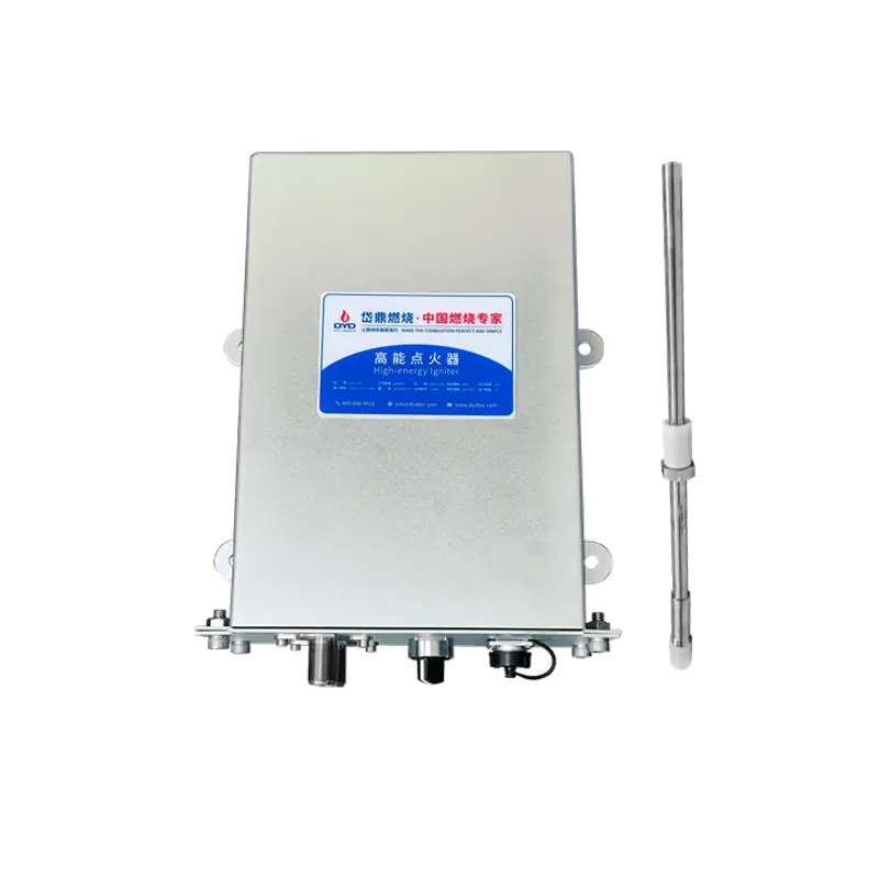
Once the proper fuel-air mixture is established, the ignition system generates a spark or pilot flame to initiate combustion. The timing and energy of ignition are critical—too weak a spark or too short an ignition period can cause delayed ignition, leading to a puffback or flame failure.
Industrial ignition systems generally include:
Ignition transformer – produces a high-voltage spark (typically 4–20 Joules of spark energy).
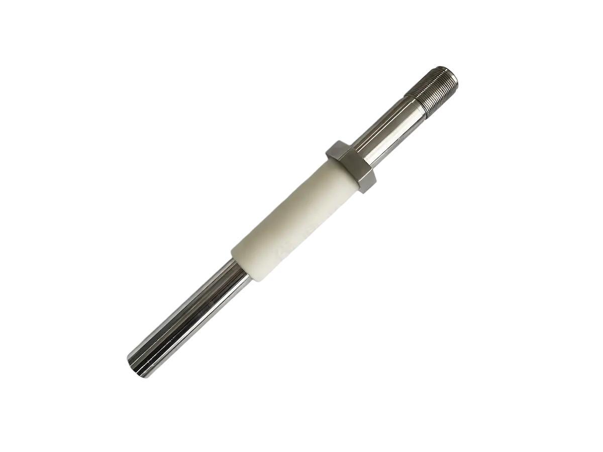
Ignition electrode – positioned in the flame zone, with a precise gap (typically 2–4 mm) to generate a reliable spark.
Pilot burner (where applicable) – a small, continuously burning flame that ignites the main burner; often used for large burners or low-NOx applications.
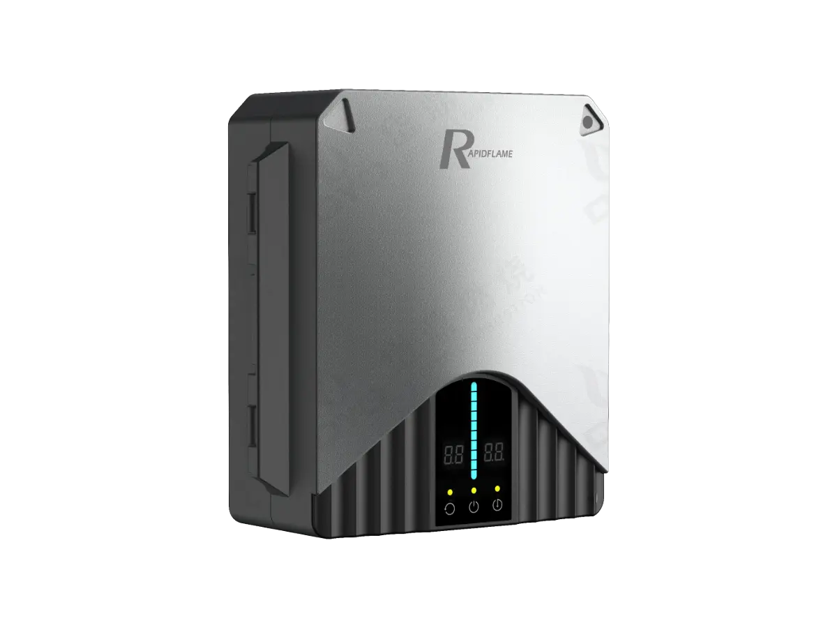
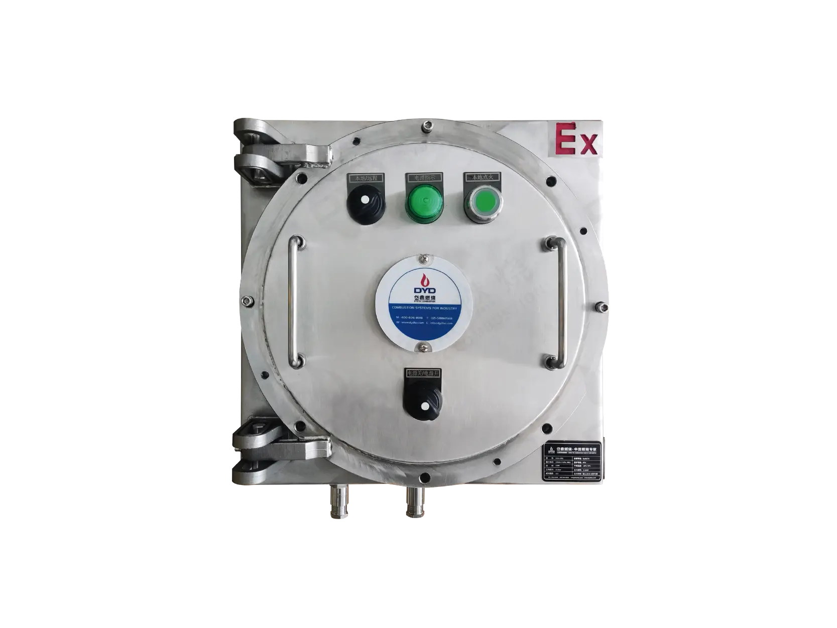
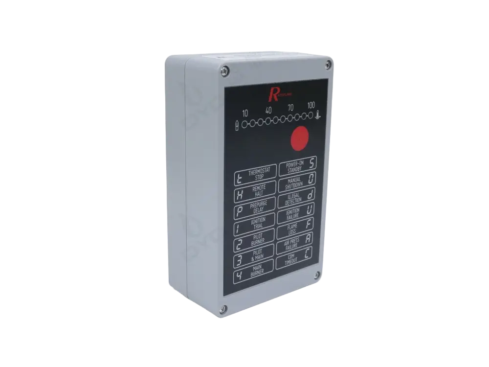
Burner management system (BMS) – controls the ignition sequence, including purging, spark timing, and flame verification.
After ignition, the main flame develops and becomes self-sustaining. The ignition period is typically 3–5 seconds; if flame is not detected within this window, the BMS shuts off the fuel and alarms.
Following ignition, the burner enters normal operating mode. The combustion control system continuously adjusts fuel flow, airflow, burner output, and flame supervision to maintain optimal combustion under varying process demands.
The control system continuously adjusts:
Fuel flow – via the modulating gas valve, responding to the temperature controller's output signal.
Airflow – via the air damper or VFD, maintaining the target air-fuel ratio at each firing point.
Burner output – modulating from high fire to low fire as process heat demand changes.
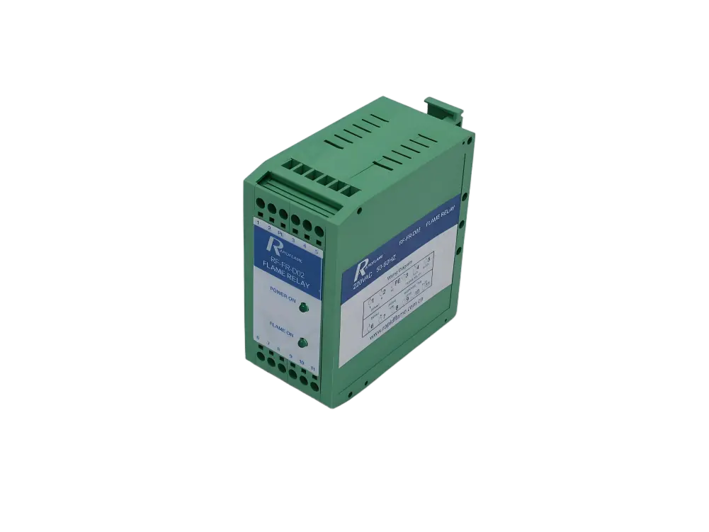
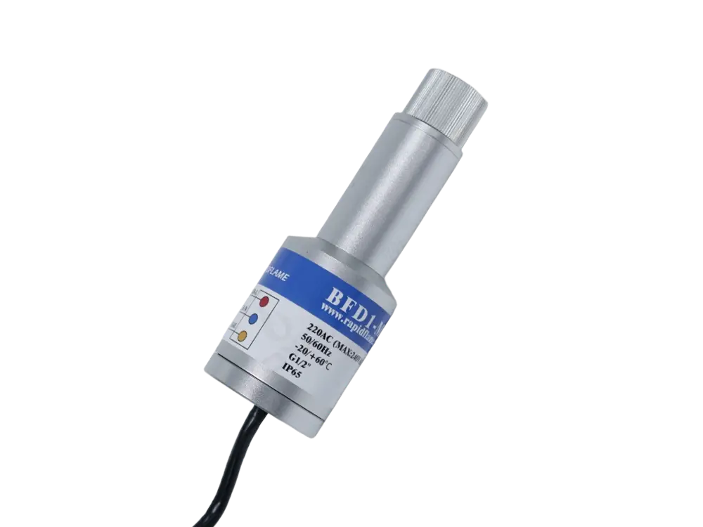
Flame supervision – ensuring the flame remains present and stable; if lost, fuel is shut off within 1–3 seconds.
This allows the burner to respond to changing process demands while maintaining stable combustion, consistent heat output, high efficiency, and safe operation across the entire turndown range.
Natural gas burns efficiently only when mixed with the correct amount of combustion air. The air-to-fuel ratio directly determines whether combustion is complete, whether the flame is stable, and how much heat is lost through the exhaust.
A fuel-rich mixture causes:
Carbon monoxide formation – incomplete oxidation of carbon; CO can exceed 500–1,000 ppm.
Soot – carbon particles form and deposit on surfaces.
Unburned fuel – hydrocarbons pass through the furnace unburned, wasting energy.
Lower efficiency – chemical energy is not fully released.
Flame instability – the flame becomes long, soft, and prone to lift-off.
A lean mixture causes:
Lower flame temperature – extra nitrogen and oxygen absorb heat; each 10% excess air reduces flame temperature by 30–50°C.
Increased stack losses – heated air exits the stack, carrying away useful energy.
Higher fuel consumption – more fuel is needed to compensate for the cooling effect.
Reduced thermal efficiency – lower heat transfer and higher exhaust losses.
The objective is to maintain the optimum air-to-fuel ratio with the minimum safe amount of excess air—typically 5–15% for natural gas burners, corresponding to 2–4% O₂ in the dry flue gas.
Industrial burners are designed to prevent the flame from blowing off or flashing back. Flame stability is achieved through a combination of aerodynamic and geometric features that create a controlled recirculation zone.
Flame stability depends on:
Burner head geometry – the shape of the flame port, diffuser, and retention ring.
Air swirl – swirling the combustion air creates a central recirculation zone that continuously ignites fresh mixture.
Gas injection pattern – the number, angle, and placement of fuel jets determine how fuel interacts with the air stream.
Air velocity – must be matched to the flame speed of the mixture; too high causes lift-off, too low causes flashback.
Fuel pressure – stable pressure ensures consistent injection velocity and mixture strength.
Furnace pressure – backpressure affects air velocity and flame anchoring.
Modern burner designs create controlled recirculation zones that continuously ignite fresh fuel-air mixtures, allowing the flame to remain anchored to the burner even at low firing rates. A well-designed flame retention ring is often the key component that achieves this.
The flame itself is only the heat source. Useful heating occurs through three heat-transfer mechanisms, and the dominance of each depends on the furnace temperature and design.
The flame emits thermal radiation that directly heats furnace walls and the workpiece. Radiation is the dominant mechanism at high temperatures (above 800°C) and is proportional to the fourth power of the absolute temperature (Stefan-Boltzmann law). It is especially important in aluminum melting furnaces, glass furnaces, and steel reheating furnaces, where the flame's luminosity and emissivity are critical for efficient heat transfer.
Hot combustion gases circulate throughout the furnace and transfer heat to the load by direct contact. Convective heat transfer depends on gas velocity, temperature difference, and the surface area of the load. It is especially important in ovens, dryers, and forced-air heat treatment furnaces, where high-velocity burners and recirculating fans enhance heat transfer.
Heat flows through furnace walls, refractory materials, and the product itself after radiant and convective heating. Conduction is the slowest mechanism but is essential for heat distribution within thick workpieces and through the furnace structure. Thermal conductivity and the temperature gradient determine the rate of conductive heat transfer.
Efficient industrial heating depends on optimizing all three mechanisms through burner selection, flame shaping, furnace design, and product loading. A burner that produces a highly radiative flame (luminous, with soot particles) is preferable for high-temperature applications, while a burner that produces a clean, high-velocity flame is better for convection-dominated processes.
Today's industrial burners automatically regulate combustion using intelligent control systems. These systems ensure that the air-fuel ratio, firing rate, and safety functions are maintained without constant operator intervention.
Typical technologies include:
Maintains accurate fuel-air mixing throughout the firing range by using digital mapping of air and fuel actuator positions. Unlike mechanical linkages, electronic controls compensate for wear and environmental changes, maintaining ratio accuracy within ±1–2%.
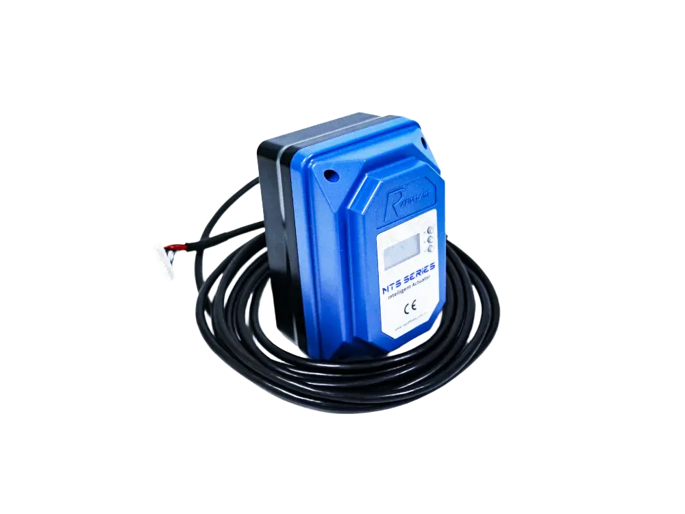
Precisely position gas valves and combustion air dampers with position feedback. Servo motors respond quickly to control signals, allowing smooth modulation and accurate flow control at every firing point.
Adjust combustion air fan speed according to burner load, providing linear airflow control without the nonlinearities of damper throttling. VFDs also reduce electrical consumption by 30–50% at low fire.
Continuously monitor flue gas oxygen and automatically optimize combustion efficiency by adjusting the air supply. These closed-loop systems compensate for changes in fuel composition, ambient temperature, and air density, delivering fuel savings of 1–3%.
Coordinate startup sequence, furnace purge, ignition, flame monitoring, safety shutdown, and fault diagnostics. The BMS ensures that the burner starts, runs, and stops safely according to a programmed sequence, while logging events for troubleshooting and predictive maintenance.
Automation improves both safety and combustion performance by reducing operator error and enabling real-time optimization.
Combustion quality depends on many variables, each of which must be controlled within acceptable limits for safe and efficient operation.
Air-to-fuel ratio – the single most important variable; determines completeness and efficiency.
Excess air – the margin above stoichiometric; too little causes CO, too much wastes heat.
Gas pressure – stability ensures consistent flow and flame anchoring.
Burner design – mixing quality, flame retention, and turndown capability.
Flame stability – anchored flame without lift-off, flashback, or pulsation.
Burner turndown ratio – ability to maintain stable combustion at low loads.
Combustion air temperature – higher air temperature increases flame temperature but may increase NOx.
Furnace pressure – affects flame shape and the work of the combustion air fan.
Control system accuracy – precise positioning and fast response maintain stable AFR.
Fuel quality – variations in Wobbe Index or moisture content affect air requirements.
All of these factors influence efficiency, emissions, and process stability. A systematic approach to combustion management addresses each of them.
Poor combustion may produce symptoms such as:
High fuel consumption – fuel bills increase without increased production.
Yellow flames – indicates carbon particles from fuel-rich zones.
Carbon monoxide – CO above 50 ppm indicates incomplete combustion.
Flame pulsation – the flame oscillates, causing pressure waves and uneven heating.
Burner cycling – frequent start-stop cycles due to poor turndown or instability.
Carbon deposits – soot buildup on burner heads and heat exchangers.
Temperature fluctuations – unstable heat output causes ±5°C or more variation.
High NOx emissions – may indicate over-firing or excessive flame temperature.
Frequent burner shutdowns – nuisance flame failures disrupt production.
Regular combustion tuning—using a flue gas analyzer to check O₂ and CO at multiple firing points—helps prevent these issues. Early detection and correction are essential for maintaining high efficiency and low emissions.
Industrial users can improve combustion performance by:
Optimizing the air-to-fuel ratio – tuning at multiple firing points to achieve low CO and moderate O₂.
Maintaining proper excess air – setting excess air as low as possible while ensuring flame stability.
Regularly tuning burners – performing combustion checks at least annually or after any fuel or equipment change.
Monitoring flue gas oxygen and CO – using portable or continuous analyzers to detect drift early.
Cleaning burner heads – removing carbon and dust deposits that affect mixing.
Maintaining stable gas pressure – ensuring regulators are functioning correctly.
Servicing ignition systems – checking spark electrodes and flame detectors.
Installing oxygen trim systems – closed-loop control that automatically compensates for changes.
Using electronic combustion controls – upgrading from mechanical linkages for better accuracy.
Performing preventive maintenance – following a structured inspection and cleaning schedule.
Small improvements in combustion control can produce significant long-term fuel savings. A 2% improvement in efficiency for a 1 MW furnace operating 8,000 hours per year can save approximately 160,000 kWh of energy annually.
No. Natural gas requires oxygen supplied by combustion air (or pure oxygen in oxy-fuel systems) to support combustion. Without oxygen, the gas will not ignite, and combustion cannot proceed.
Perfect fuel-air mixing is impossible in real operating conditions. A controlled amount of excess air ensures complete combustion and stable flame operation while maintaining safety. The excess air compensates for uneven mixing, fuel pressure fluctuations, and load variations, preventing local fuel-rich zones that would produce CO and soot.
A properly adjusted industrial natural gas burner typically produces a stable blue flame. The blue colour indicates complete combustion, with the flame front emitting radiation from intermediate species (CH and C₂ radicals). Yellow or orange flames indicate carbon particle formation from fuel-rich zones, which is a sign of poor mixing or insufficient air.
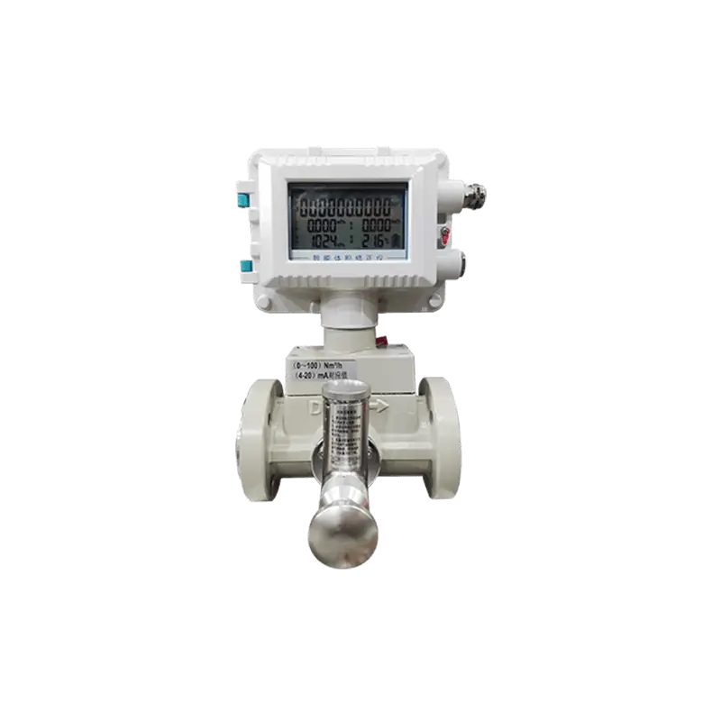
Industrial combustion is commonly monitored using flame detectors (UV, IR, or ionization), oxygen analyzers in the flue gas, carbon monoxide analyzers, pressure sensors, temperature sensors, and burner management systems. These instruments provide real-time data that allows operators and automatic control systems to maintain optimal combustion conditions.
Yes. Proper burner tuning, optimized air-fuel ratio, oxygen trim systems, preventive maintenance, and advanced combustion controls can significantly improve combustion efficiency while reducing fuel consumption and emissions. For most industrial furnaces, a structured combustion optimisation programme can deliver 3–8% fuel savings with a payback period of 6–18 months.
Natural gas combustion in an industrial burner is a precisely controlled process that transforms the chemical energy of methane into useful thermal energy. Successful combustion depends on accurate fuel-air mixing, reliable ignition, stable flame formation, intelligent combustion control, and continuous monitoring.
By optimizing the air-to-fuel ratio, minimizing excess air, maintaining stable gas pressure, and using advanced burner management technologies, industrial facilities can achieve higher combustion efficiency, lower emissions, improved temperature control, and reduced operating costs. Modern industrial burners are designed not only to generate heat but also to deliver safe, reliable, and energy-efficient performance across a wide range of industrial heating applications.
DYDTEC Combustion is a professional manufacturer of industrial combustion systems and advanced burner solutions. The company specializes in high-efficiency gas burners, low-NOx combustion technology, intelligent burner management systems, and customized heating solutions for industrial furnaces, aluminum melting, heat treatment, drying equipment, RTO systems, and other thermal processing applications. Through advanced burner engineering, precise combustion control, and application-specific system integration, DYDTEC helps furnace manufacturers and industrial users improve combustion efficiency, reduce fuel consumption, lower emissions, and achieve safe, reliable, and long-term industrial heating performance.