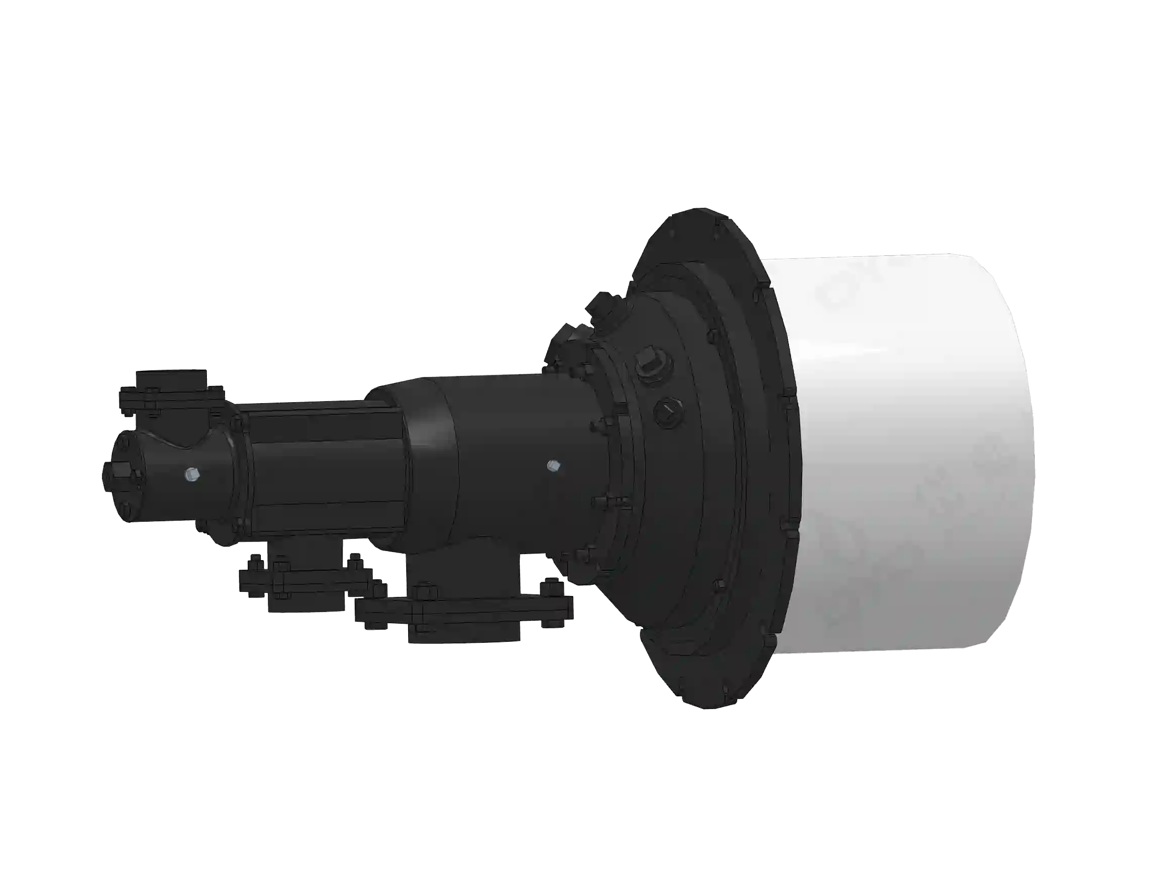
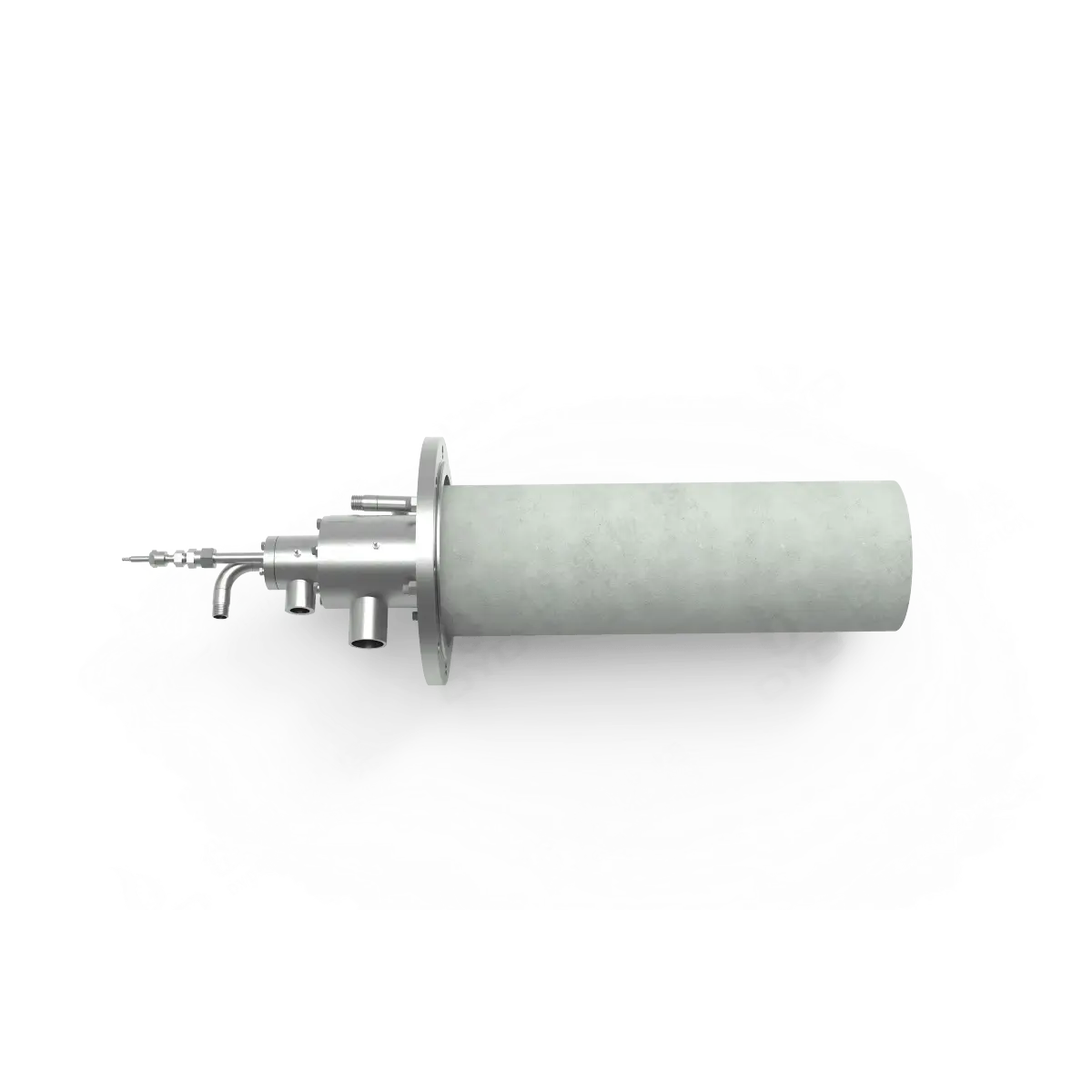
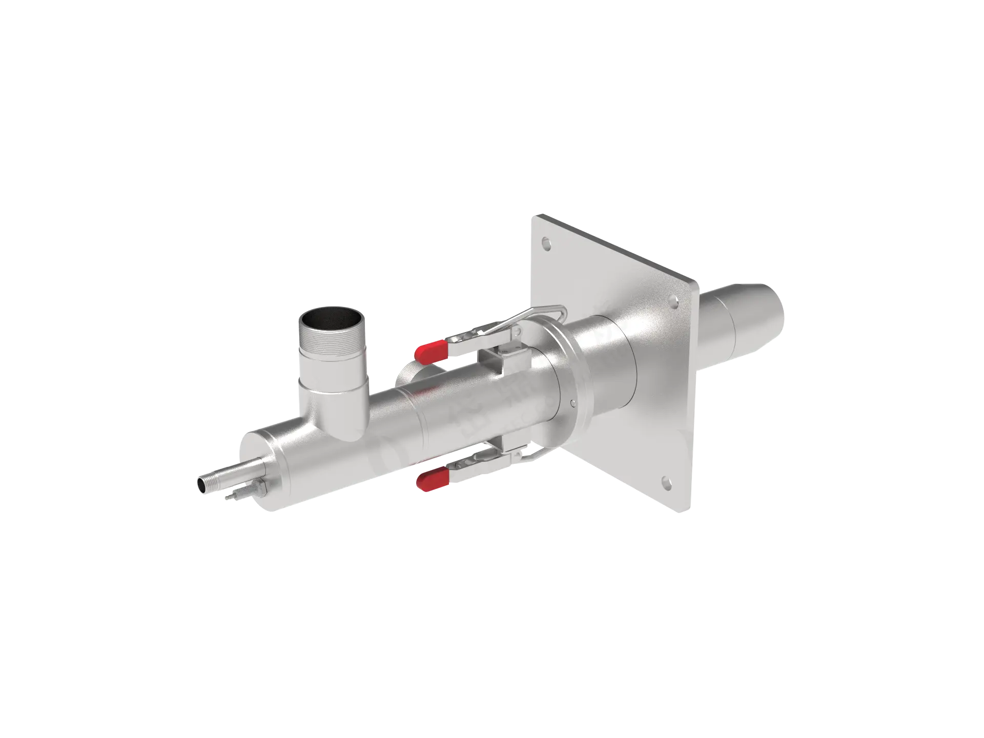
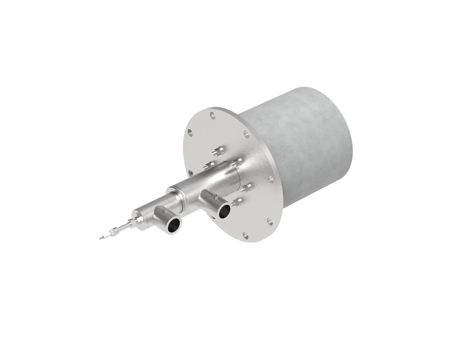
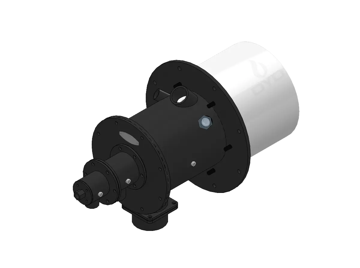
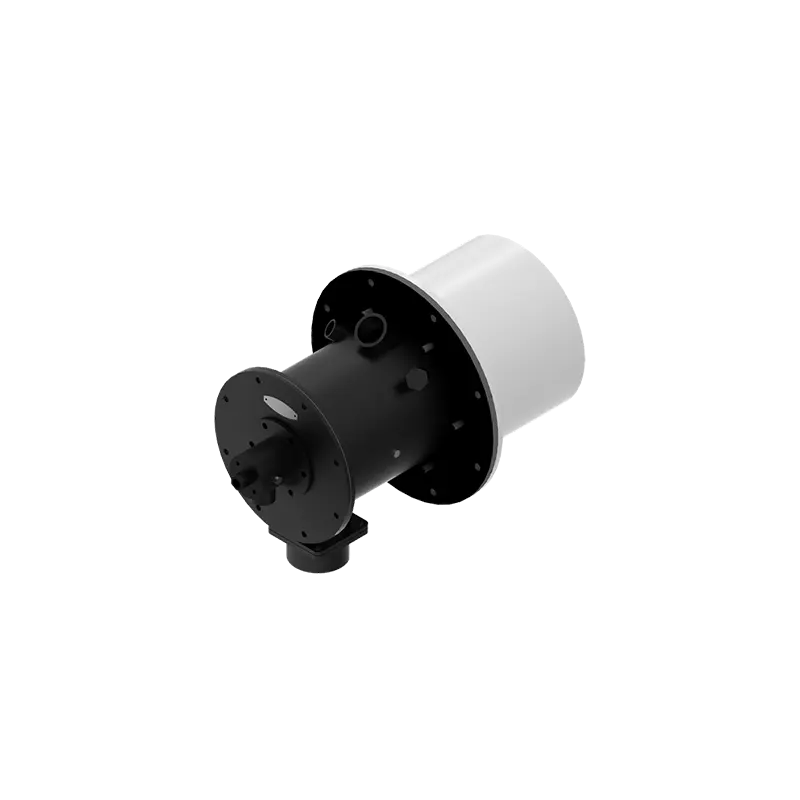
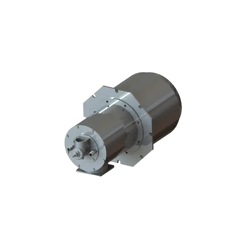
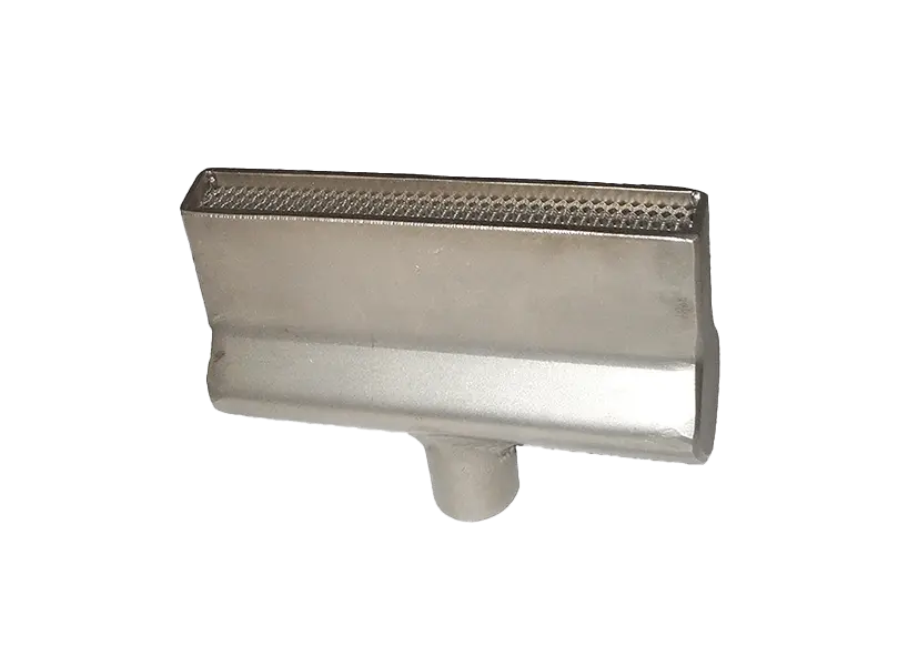
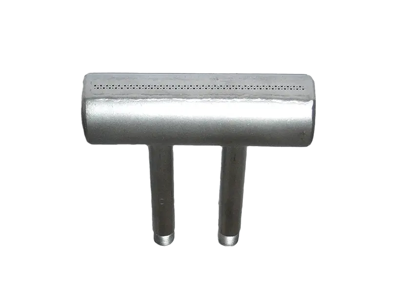
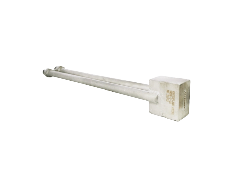
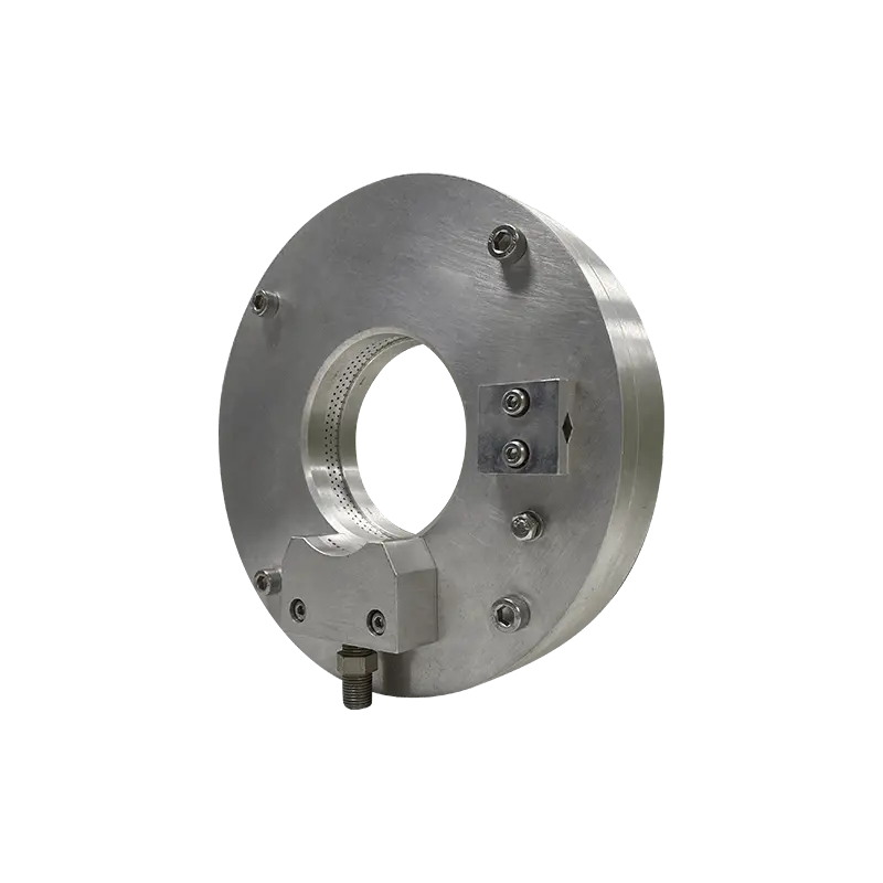
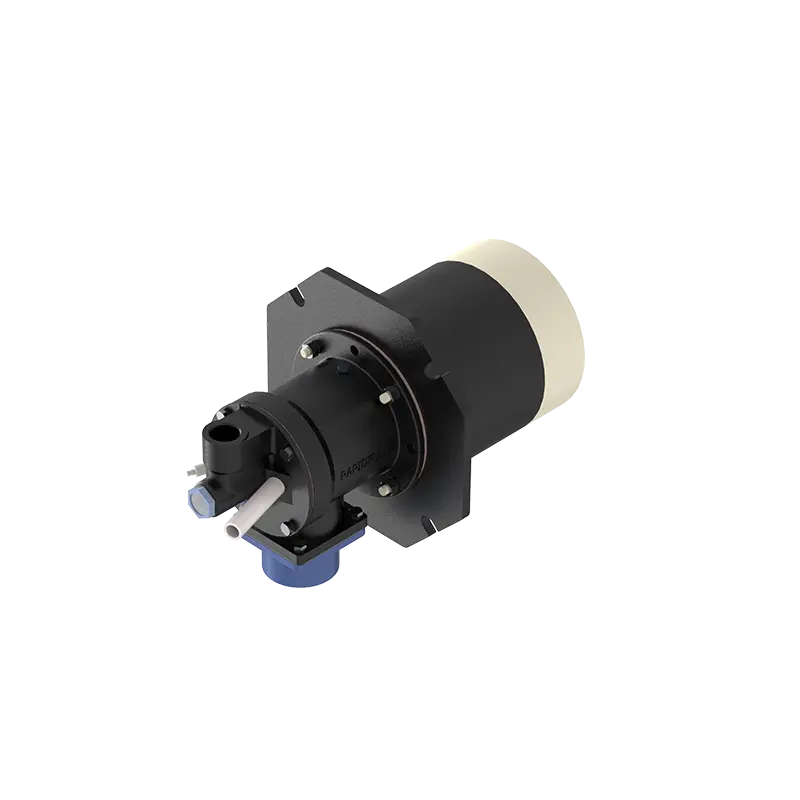
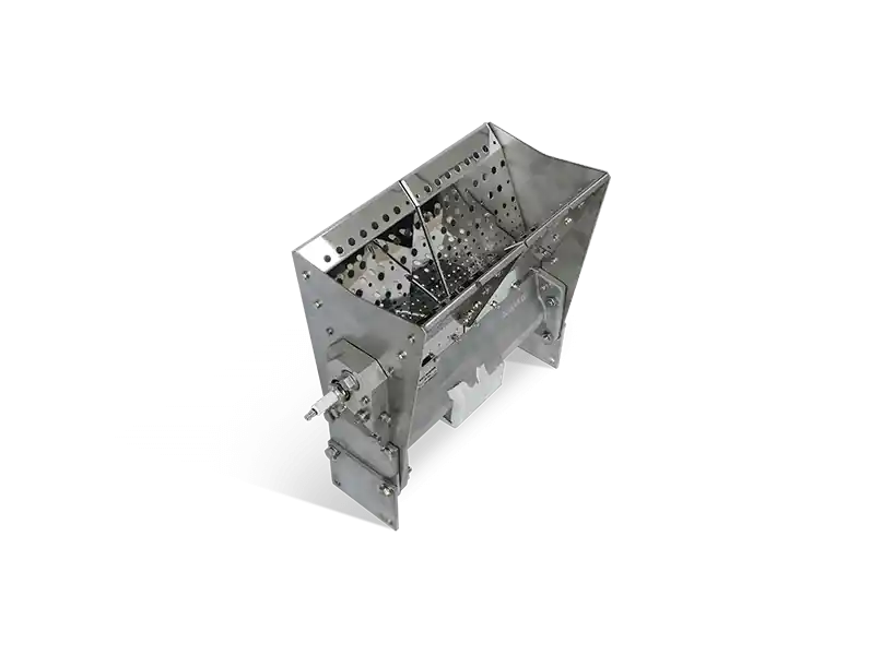
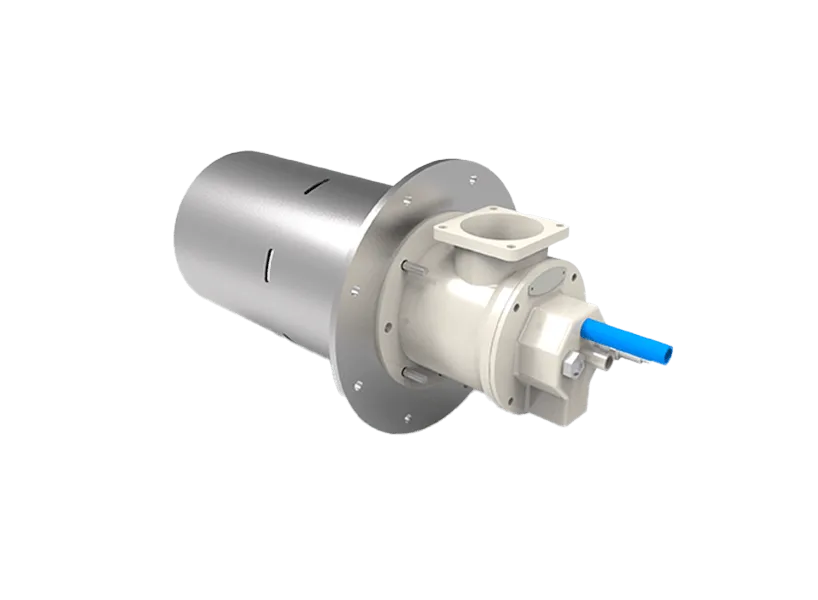
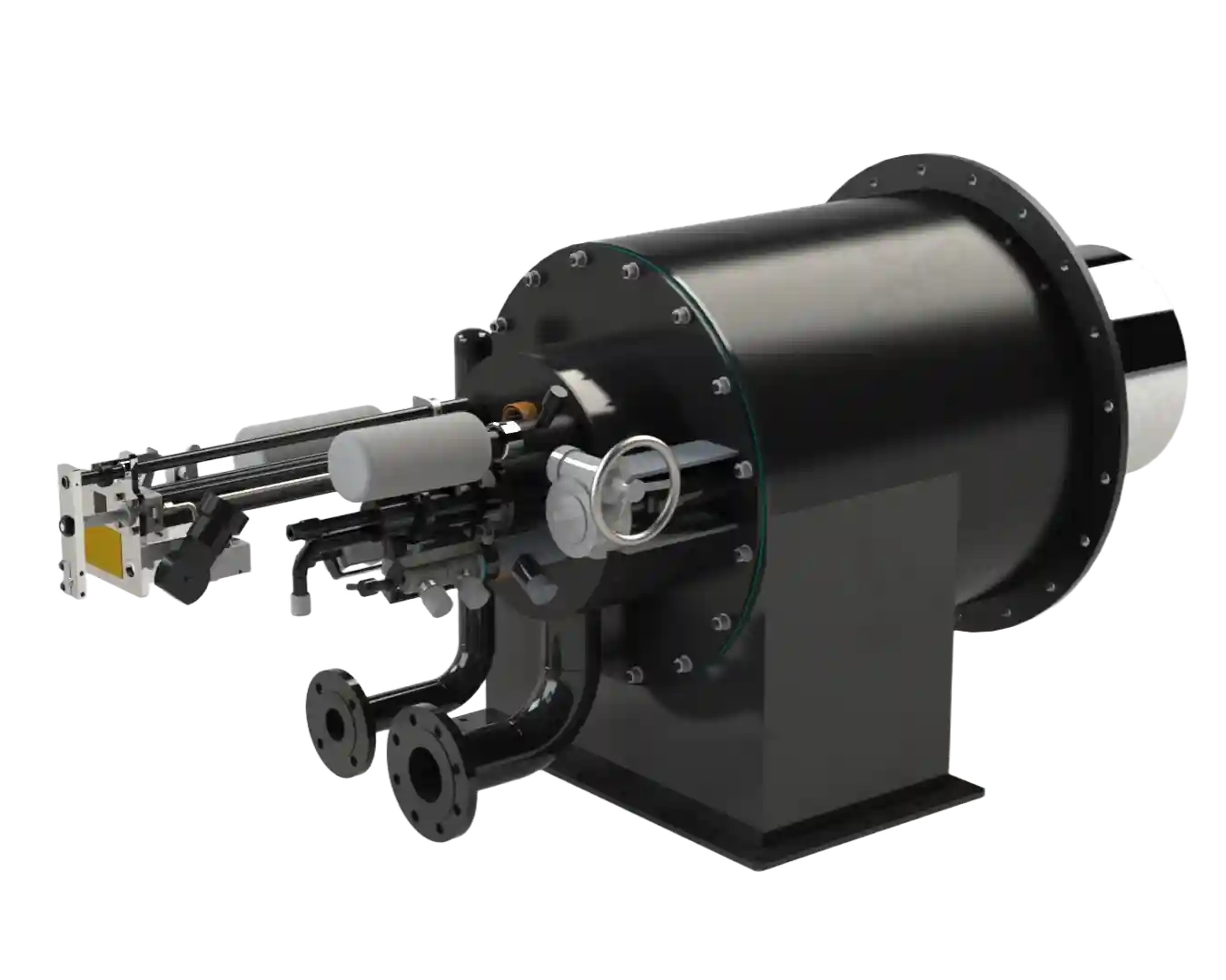
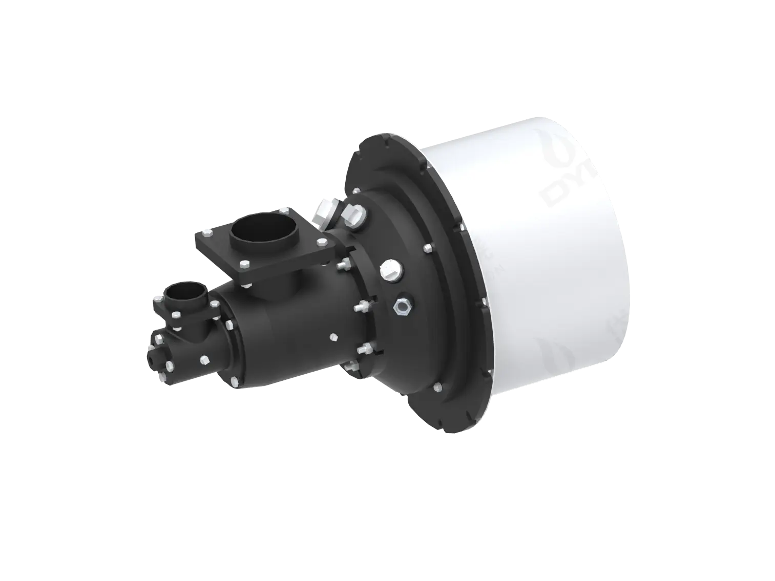
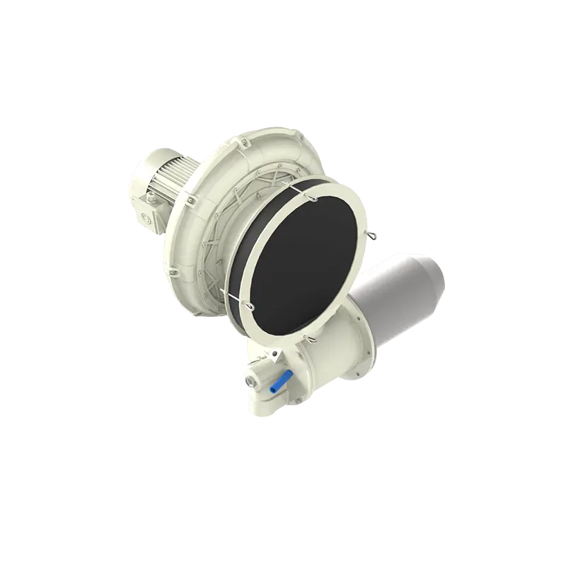
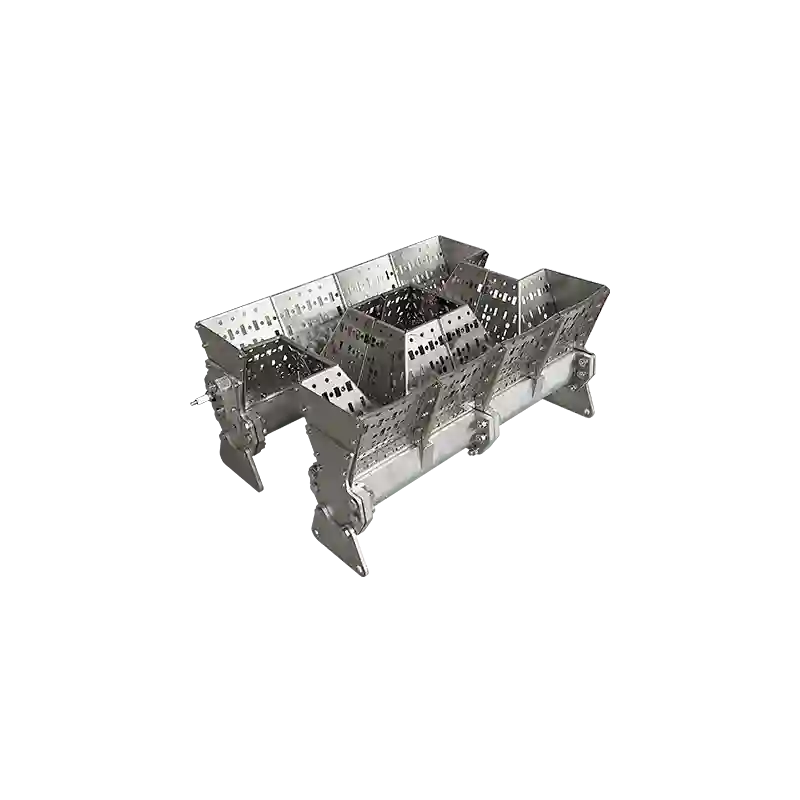
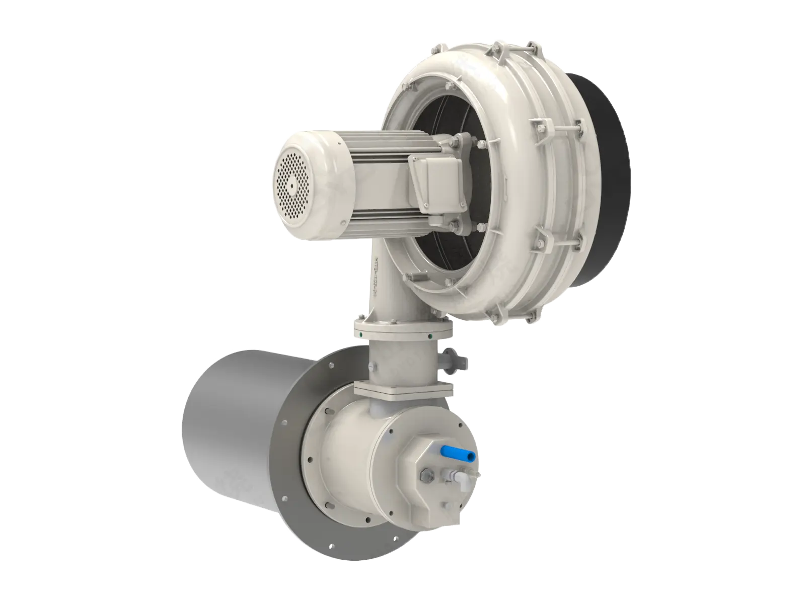
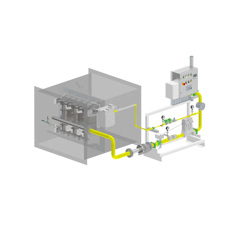
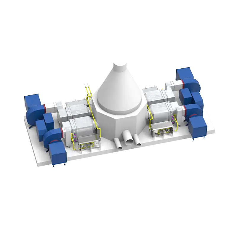
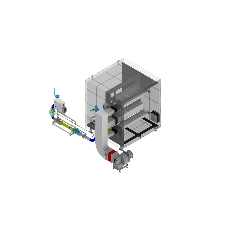
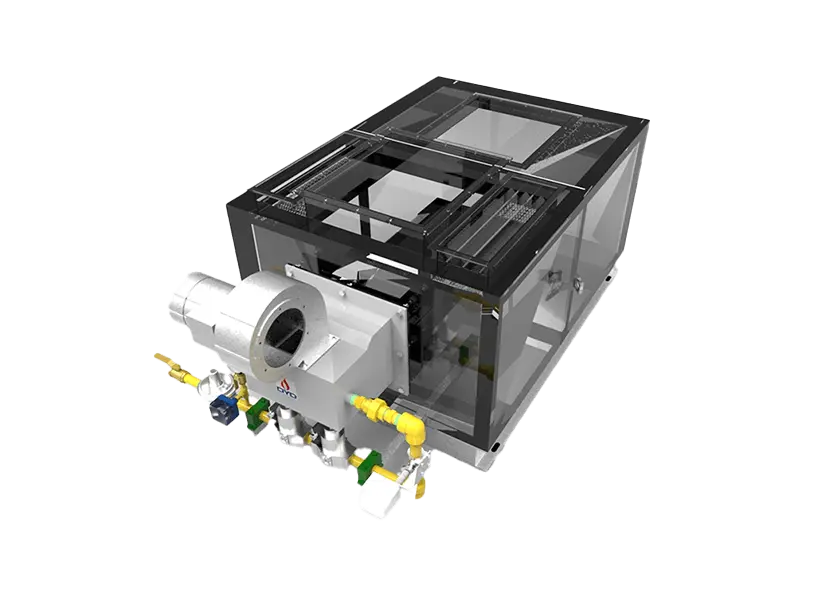
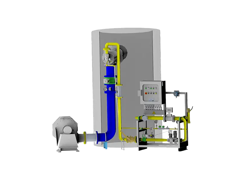
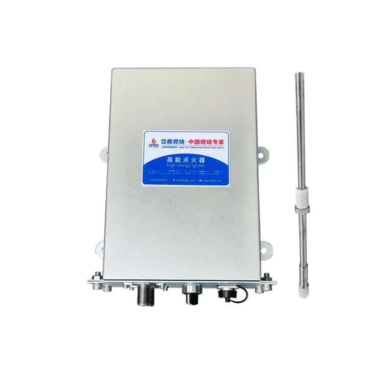
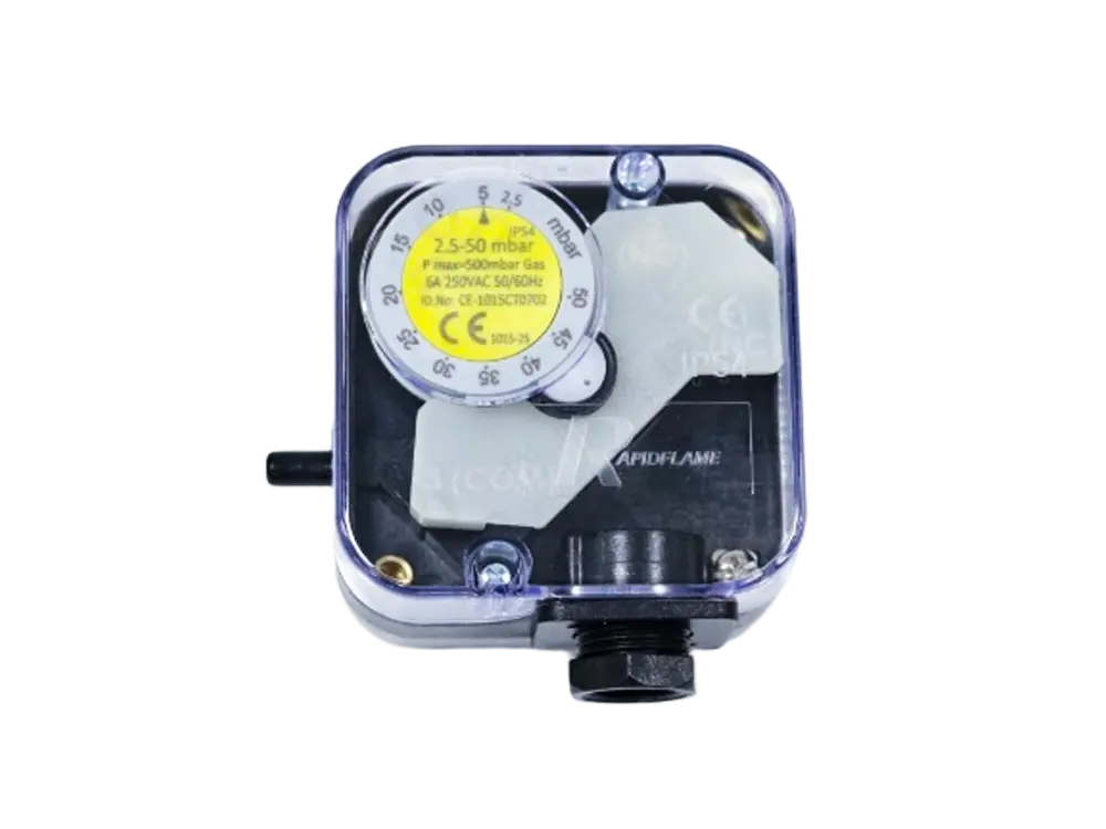
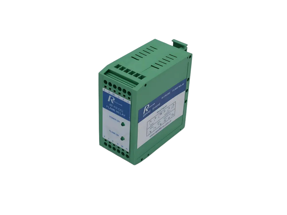
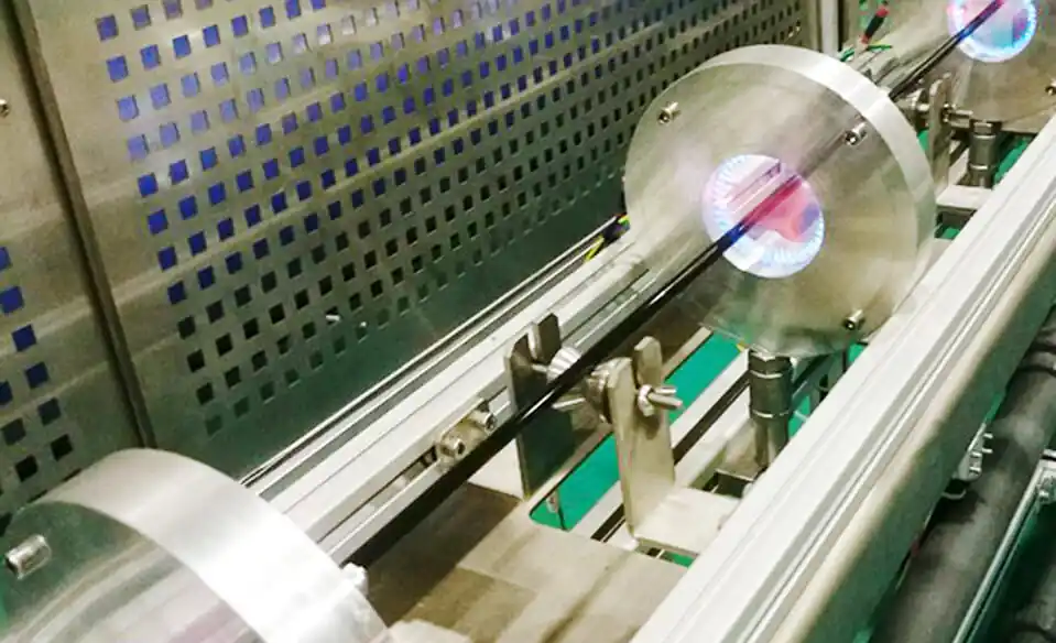
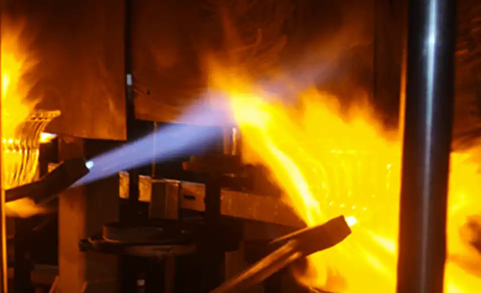
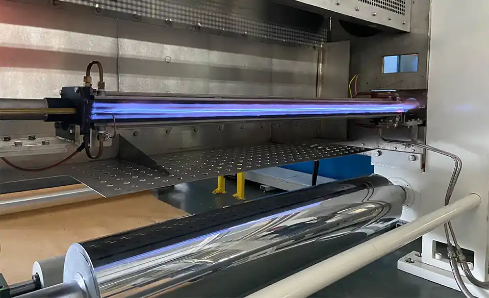
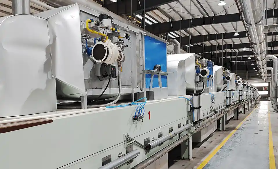
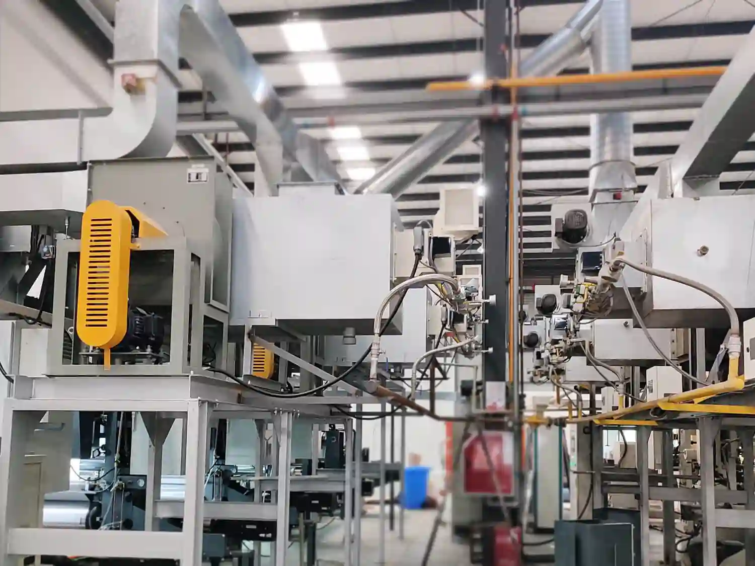
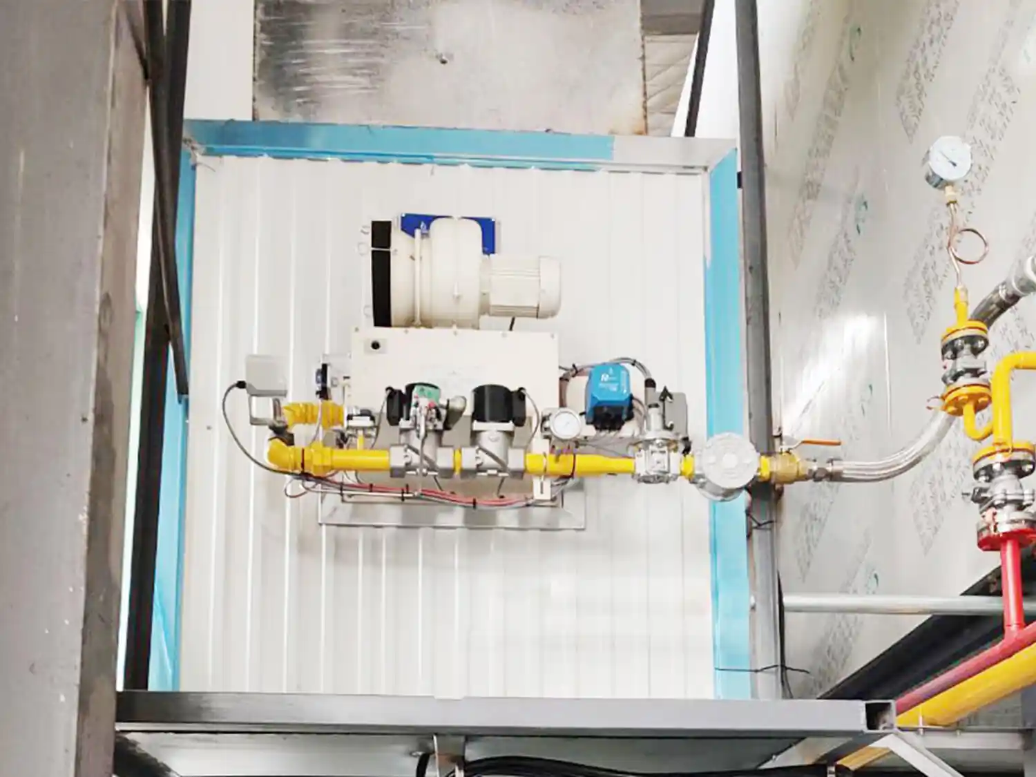
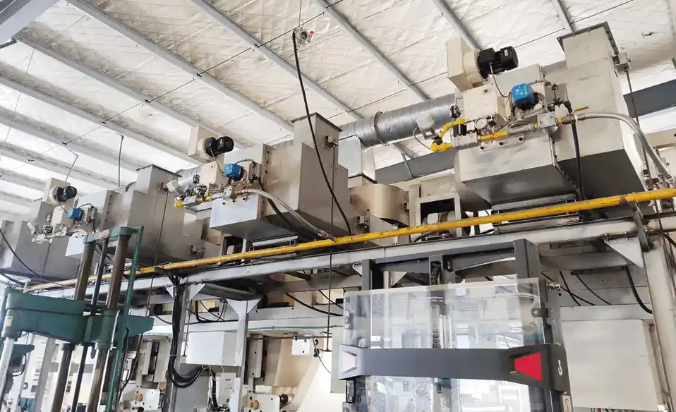
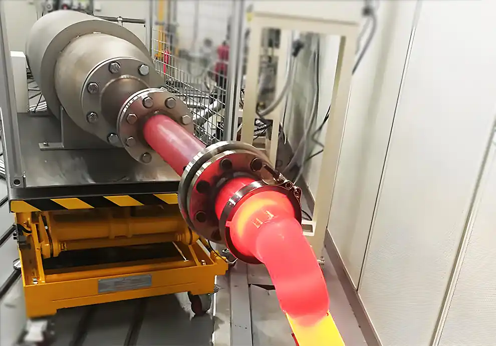
The burner head is the core component where fuel, combustion air, and ignition energy come together to create and stabilize the flame. Although it may appear to be a simple mechanical part—perhaps just a metal casting with some holes and passages—the burner head is actually a highly engineered structure that controls fuel injection, air distribution, mixing quality, flame shape, combustion stability, and emissions performance. Its internal geometry and aerodynamic features are the result of careful fluid dynamics analysis, materials selection, and extensive testing under real operating conditions.
In industrial burners, the burner head determines many critical combustion characteristics, including:
Flame stability, ensuring the reaction remains anchored and continuous.
Flame length and shape, defining the spatial footprint of heat release.
Heat release distribution, controlling where thermal energy is delivered within the chamber.
Fuel-air mixing efficiency, governing combustion completeness and energy utilization.
NOx and CO emissions, directly influenced by mixing patterns and temperature profiles.
Operating range, determining the turndown ratio and load flexibility of the burner.
Whether used in furnaces, dryers, kilns, thermal oxidizers, or industrial heating systems, the burner head plays a decisive role in converting fuel energy into usable heat. It is the interface between the fuel supply system and the combustion chamber, and its performance ultimately determines the efficiency, reliability, and environmental footprint of the entire thermal process.
The burner head is the front section of an industrial burner where fuel and combustion air are discharged into the furnace and where the flame is formed. It is the terminal element of the burner assembly, positioned at the boundary between the burner body and the furnace interior.
It typically contains:
Fuel nozzles or injection ports that meter and direct the fuel stream.
Air outlet passages that shape and distribute the combustion air.
Mixing structures that promote contact between fuel and oxidizer.
Flame stabilization components that anchor the reaction zone.
Ignition positioning features that ensure reliable startup.
Its main functions are:
Deliver fuel into the combustion zone at the correct velocity, angle, and distribution.
Control combustion air distribution to achieve the desired flow pattern and turbulence.
Promote fuel-air mixing to enable complete and efficient oxidation.
Stabilize the flame by creating recirculation zones that continuously re-ignite the incoming mixture.
Shape the flame according to process requirements, matching the thermal needs of the specific application.
A well-designed burner head allows the flame to remain stable under different operating conditions, from low-fire startup to high-fire production, while maintaining consistent heat release and emission performance.
The combustion process inside and around the burner head can be divided into several sequential stages, each of which contributes to the overall behavior of the flame. These stages occur in rapid succession, often within milliseconds, and are tightly coupled through the fluid dynamics of the flow field.
The first step occurs when fuel enters the burner head from the supply manifold and is discharged through the fuel injection system. This is the point at which the chemical energy source transitions from a confined pipe flow to a free jet that will interact with the combustion air.
Depending on burner design, fuel may enter through:
Central gas nozzles that discharge fuel along the burner axis.
Multiple injection holes arranged radially or circumferentially.
Annular fuel passages that surround the air stream.
High-speed fuel jets that penetrate the air flow for enhanced mixing.
The purpose of fuel injection is not simply to release gas, but to create the correct combination of:
Velocity, which determines how far and how fast the fuel travels.
Distribution, ensuring that fuel is spread across the air stream.
Direction, controlling the angle at which fuel meets the oxidizer.
Penetration pattern, governing how deeply the fuel jet reaches into the combustion air.
The fuel jet characteristics directly affect:
Mixing quality, as the momentum and turbulence of the jet determine how quickly fuel and air intermingle.
Flame shape, since the spatial distribution of fuel defines where the reaction zone develops.
Combustion stability, as the jet's interaction with the burner head's stabilizing features determines anchoring reliability.
At the same time that fuel is being injected, combustion air flows through the burner head from the air plenum or fan system. The burner head acts as the final shaping element for the oxidizer stream, controlling its aerodynamic properties before it enters the combustion zone.
The burner head controls:
Air velocity, which affects mixing intensity and flame momentum.
Air direction, determining how the air stream approaches and interacts with the fuel jets.
Air quantity, distributing the flow across the available cross-section.
Turbulence intensity, which promotes molecular-level contact between fuel and oxygen.
Common air flow designs include:
Air moves straight into the furnace along the burner axis, without significant rotational motion.
Advantages:
Simple structure that is easy to manufacture and maintain.
Stable operation across a wide range of firing rates.
Air rotates before entering the furnace, typically achieved through fixed vanes or adjustable swirl generators.
Advantages:
Improved mixing through increased shear between the rotating air and the fuel stream.
Strong internal recirculation that draws hot combustion products back to the flame root.
Better flame stabilization, as the recirculation zone provides a continuous source of ignition energy.
Swirl is widely used in industrial burners because it helps create a stable combustion zone that is less sensitive to variations in fuel composition, air supply, or furnace pressure.
The most important function of the burner head is creating effective mixing between fuel and air. This mixing is the prerequisite for combustion: without intimate contact between fuel molecules and oxygen molecules, the chemical reaction cannot proceed to completion.
Efficient mixing ensures:
Every fuel molecule receives enough oxygen to oxidize completely.
Combustion occurs completely, with minimal unburned species in the exhaust.
Heat release is controlled, avoiding localized hot spots that could damage equipment or increase emissions.
Poor mixing can lead to:
High CO emissions, as fuel-rich pockets pass through the reaction zone without finding sufficient oxygen.
Flame instability, as variations in local equivalence ratio cause the flame to fluctuate.
Uneven heating, since the heat release is distributed irregularly across the chamber.
Increased fuel consumption, as incomplete combustion wastes a portion of the fuel's energy content.
The burner head controls mixing through a combination of geometric and aerodynamic features:
Injection angle, which determines how the fuel jets intersect the air stream.
Nozzle arrangement, governing the number, spacing, and orientation of injection points.
Air velocity, which sets the shear forces that break up the fuel jet into smaller eddies.
Turbulence generation, promoting rapid diffusion and molecular mixing.
A stable flame needs a fixed location where the reaction can anchor and persist. Without such a location, the flame would drift, oscillate, or extinguish entirely as flow conditions change.
The burner head creates a special region called the flame stabilization zone. This region is characterized by aerodynamic conditions that favor sustained ignition and flame holding.
This area usually contains:
Lower velocity regions where the local flow speed is reduced to match the flame propagation speed.
Hot combustion products that are recirculated back to the flame root, providing a continuous heat source for ignition.
Recirculated gases that create a sheltered zone where the flame can remain anchored even when main flow velocities are high.
These hot gases continuously ignite incoming fuel-air mixtures, ensuring that the flame remains attached to the burner face rather than being blown downstream.
This prevents:
Flame blow-off, where the flame detaches and extinguishes.
Flame oscillation, where the reaction zone moves back and forth unpredictably.
Ignition failure, where the flame cannot establish or re-establish after a disturbance.
Once the flame is stabilized, the burner head continues to influence its development by determining the initial conditions of the reacting flow. The geometry and aerodynamic settings of the burner head establish the starting point from which the flame evolves as it travels through the furnace.
The burner head determines the initial flame structure, including:
Flame length, which is governed by the momentum and mixing rate set at the burner head.
Flame diameter, influenced by the spread angle of the fuel-air mixture.
Flame momentum, determined by the combined velocity and mass flow of the discharged gases.
Heat release profile, shaped by how fuel and air are distributed across the burner face.
Different burner head designs create different flame characteristics to suit various process requirements.
For example:
Produces:
Long penetrating flame that reaches deep into the furnace chamber.
Strong furnace circulation that promotes uniform temperature distribution.
Used for:
Large furnaces where heat must be delivered to distant sections of the chamber.
High-temperature applications requiring rapid heat input across a large volume.
Produces:
Controlled mixing that delays the complete combination of fuel and air.
Reduced peak temperature by spreading heat release over a larger area.
Lower NOx emissions through moderation of thermal NOx formation.
Used for:
Environmental compliance applications where strict emission limits must be met.
Processes requiring stable, low-temperature combustion with minimal pollutant output.
The fuel nozzle controls the discharge of fuel into the combustion zone, acting as the final metering and directing element before the fuel enters the flame.
The fuel nozzle controls:
Fuel flow rate, ensuring the correct fuel supply for the desired heat release.
Injection direction, aiming the fuel jet toward the optimal mixing region.
Jet velocity, which affects momentum, penetration, and mixing intensity.
A damaged or incorrect nozzle can cause:
Poor flame shape, as the fuel distribution deviates from the intended pattern.
Increased emissions, resulting from incomplete mixing or uneven combustion.
Unstable combustion, if the jet characteristics fall outside the design envelope.
The swirler gives combustion air a rotational movement before it enters the furnace. It typically consists of a set of fixed or adjustable vanes arranged around the air passage.
Functions:
Improve mixing by creating shear layers between the rotating air and the fuel jets.
Create recirculation that stabilizes the flame and promotes flame holding.
Stabilize flame by providing a low-velocity recirculation zone at the burner face.
Swirl intensity is carefully designed because:
Too little swirl results in weak stabilization, making the flame susceptible to blow-off.
Too much swirl causes excessive pressure loss or unstable flow patterns that can disrupt combustion.
Some burners include a mixing section where fuel and air partially combine before combustion occurs. This chamber provides a controlled space for the two streams to interact before they are discharged into the furnace.
Its design affects:
Mixing speed, determining how quickly the fuel-air mixture approaches uniformity.
Flame stability, as pre-mixing changes the reaction kinetics and flame propagation characteristics.
Emission performance, since more homogeneous mixtures tend to produce lower CO and NOx.
The flame stabilizer creates a controlled low-velocity region where the flame can anchor securely. This is often achieved through bluff bodies, steps, or recessed cavities that interrupt the main flow.
Functions:
Hold the flame position, preventing it from drifting downstream.
Prevent blow-off by reducing local flow velocities to match flame speed.
Maintain ignition reliability by providing a stable recirculation zone.
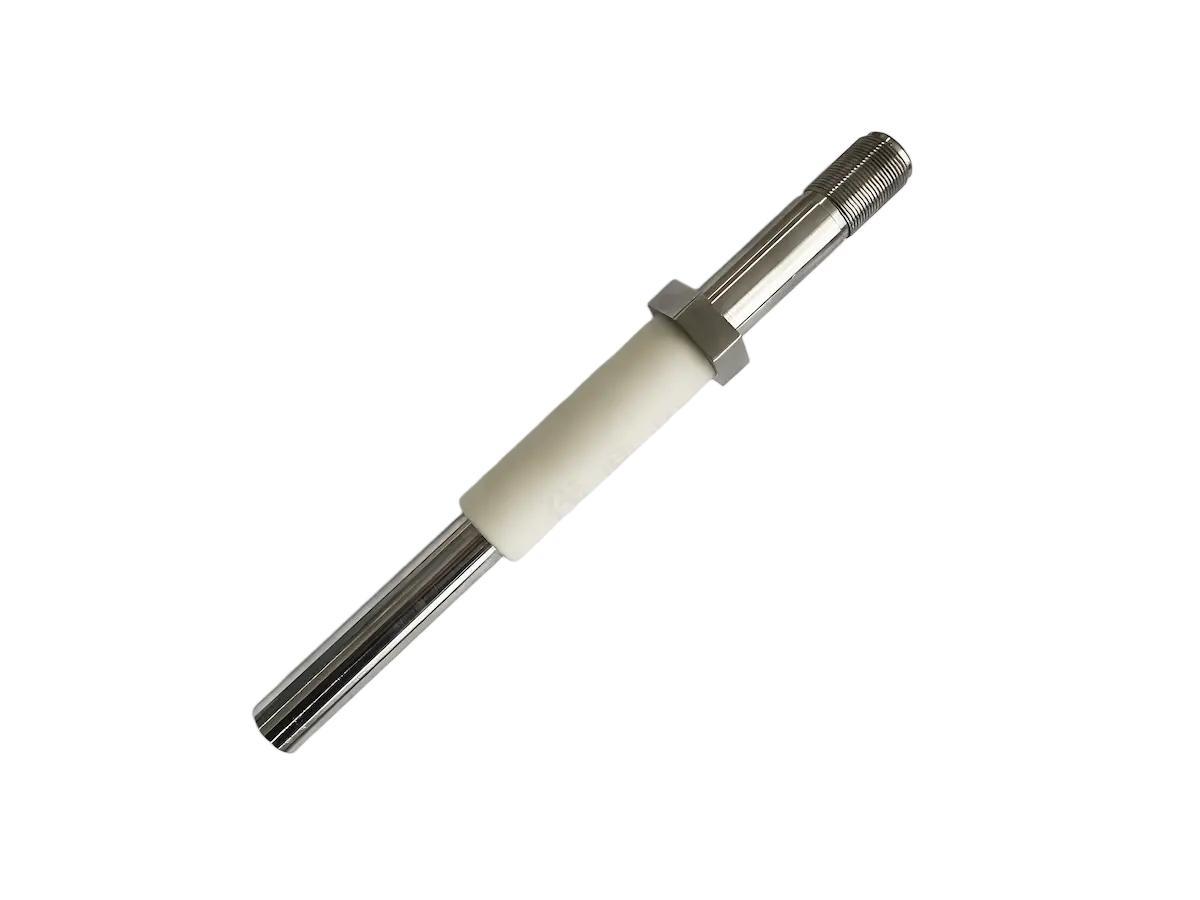
The burner head design ensures that ignition occurs at the correct location relative to the fuel-air mixture. The placement of the ignition electrode or pilot burner is critical to successful startup.
The ignition system must match:
Flame position, ensuring that the spark or pilot flame is located where the mixture is ignitable.
Fuel-air mixture characteristics, including velocity, temperature, and stoichiometry.
Burner operating range, with the ignition point remaining effective across the load range.
A good burner head prevents flame lift-off, flashback, and extinction by maintaining the correct aerodynamic and chemical balance at the flame root.
It maintains the correct balance between:
Flow velocity, which pushes the flame downstream.
Flame speed, the rate at which combustion propagates through the mixture.
Recirculation, which provides the hot products needed for continuous ignition.
Better fuel-air mixing improves the thermodynamic performance of the burner by ensuring that the reaction proceeds to completion.
Improved mixing provides:
Complete combustion, with all fuel energy released.
Heat release, concentrated where it is most effective.
Fuel utilization, minimizing waste and reducing fuel cost.
Poor burner head design may cause:
Unburned fuel, leaving the chamber as waste.
Higher CO emissions, indicating incomplete oxidation.
Lower efficiency, requiring more fuel for the same output.
Modern burner heads are designed to control pollutant formation through aerodynamic management of the reaction zone.
Technologies include:
Staged fuel injection, introducing fuel in multiple locations to avoid concentrated heat release.
Staged air supply, controlling the oxygen availability in different regions of the flame.
Internal recirculation, drawing cooled products back into the flame to moderate temperature.
Premixed combustion, blending fuel and air before ignition to achieve a uniform reaction.
Fuel and air mix after leaving the burner, relying on turbulent diffusion to bring the two streams together.
Characteristics:
High stability, as the flame is less sensitive to changes in mixture composition.
Good tolerance to fuel variation, accommodating differences in gas composition or quality.
Suitable for industrial heating where robustness and reliability are primary concerns.
Fuel and air mix before ignition, producing a homogeneous mixture that burns rapidly.
Characteristics:
Excellent mixing, with uniform fuel-air distribution across the entire reaction zone.
Lower NOx potential, as the uniform mixture avoids localized hot spots.
Requires flashback protection, since the flame can propagate backward into the mixing chamber if velocities are not properly controlled.
Creates strong gas jets that exit the burner at high speed.
Characteristics:
Strong furnace circulation, promoting even temperature distribution throughout the chamber.
Fast heat transfer through enhanced convection.
Deep penetration, delivering heat to distant areas of the furnace.
Uses elongated fuel and air distribution across a linear array of ports or a continuous slot.
Characteristics:
Wide uniform flame that covers a broad surface area.
Suitable for continuous heating processes where consistent heat input across a wide product is required.
Causes:
Poor flame pattern, with irregular or asymmetric heat release.
Uneven heating, as fuel distribution becomes skewed.
Reduced output, as the effective flow area decreases.
Causes:
Poor mixing, as the rotational flow pattern is disrupted.
Flame instability, resulting from the loss of the stabilizing recirculation zone.
Increased emissions, as mixing quality deteriorates.
Causes:
Wrong flame length, incompatible with the furnace geometry.
Poor furnace matching, resulting in temperature non-uniformity.
Reduced efficiency, as the flame does not deliver heat where it is most needed.
Causes:
Excessive furnace temperature, exceeding the material limits of the burner head.
Incorrect flame position, placing the reaction zone too close to the burner face.
Cooling problems, when insufficient cooling flow leads to thermal degradation.
Regular maintenance should include systematic checks and corrective actions to preserve performance and extend service life.
Check:
Nozzle condition for wear, erosion, or damage.
Deposits on internal surfaces, including carbon build-up and ash accumulation.
Mechanical damage from thermal stress, vibration, or handling.
Air passages for obstructions or deformation.
Remove:
Carbon deposits that can alter flow distribution.
Dust accumulation that may block small passages.
Foreign materials that could damage components or affect combustion.
Verify:
Flame appearance, confirming consistent shape, color, and intensity.
Oxygen level, indicating the air-fuel ratio.
CO emissions, reflecting combustion completeness.
Temperature distribution, confirming uniform thermal conditions.
The burner head controls fuel injection, combustion air distribution, mixing, flame stabilization, and flame shape formation. It is the primary component that determines how fuel energy is released and directed within the furnace.
Because it determines how effectively fuel and air mix. Better mixing leads to more complete combustion and higher energy efficiency. The burner head's aerodynamic design is the main factor controlling the rate and uniformity of mixing.
Yes. Burner head design directly determines flame length, width, momentum, and heat release distribution. The geometry of the nozzle, swirler, and mixing passages defines the initial conditions from which the flame develops.
Low-NOx combustion requires precise control of mixing and temperature. The burner head creates controlled combustion zones that reduce peak flame temperatures, limiting thermal NOx formation while maintaining stable combustion.
A damaged burner head can cause unstable flames, incomplete combustion, higher emissions, uneven heating, and increased fuel consumption. Damage can also lead to premature failure of other furnace components and increased maintenance costs.
The burner head is the heart of an industrial burner, where fuel injection, air distribution, mixing, and flame stabilization happen simultaneously. It is the convergence point where all the key inputs—fuel, air, and ignition energy—are brought together in a precisely controlled manner.
Its design determines:
How fuel and air combine, influencing the reaction kinetics and heat release.
Where the flame forms, establishing the primary heating zone within the chamber.
How heat is released, shaping the temperature profile and transfer efficiency.
How efficiently fuel is converted into useful energy, affecting operating costs and environmental impact.
A properly engineered burner head allows industrial combustion systems to achieve:
Stable flames that remain anchored and consistent across the operating range.
High efficiency through complete combustion and effective heat transfer.
Low emissions through controlled mixing and temperature moderation.
Uniform heating that supports consistent product quality and reduced reject rates.
Long operating life through robust construction and resistance to thermal and mechanical stress.
For modern industrial burners, the burner head is not just a fuel outlet — it is a precision combustion control device that determines the overall performance of the entire heating system. Its design, condition, and compatibility with the furnace are essential factors in achieving reliable, efficient, and environmentally responsible thermal processing.
DYDTEC Combustion specializes in industrial burner technology, combustion systems, and customized thermal solutions. The company develops industrial burner solutions for furnaces, drying equipment, thermal processing systems, and energy-efficient heating applications, focusing on advanced burner head design, optimized fuel-air mixing, stable flame control, low emissions, and reliable long-term operation. With deep expertise in burner head aerodynamics, materials science, and combustion engineering, DYDTEC supports customers in selecting, designing, and maintaining burner systems that deliver consistent process performance and operational cost savings.