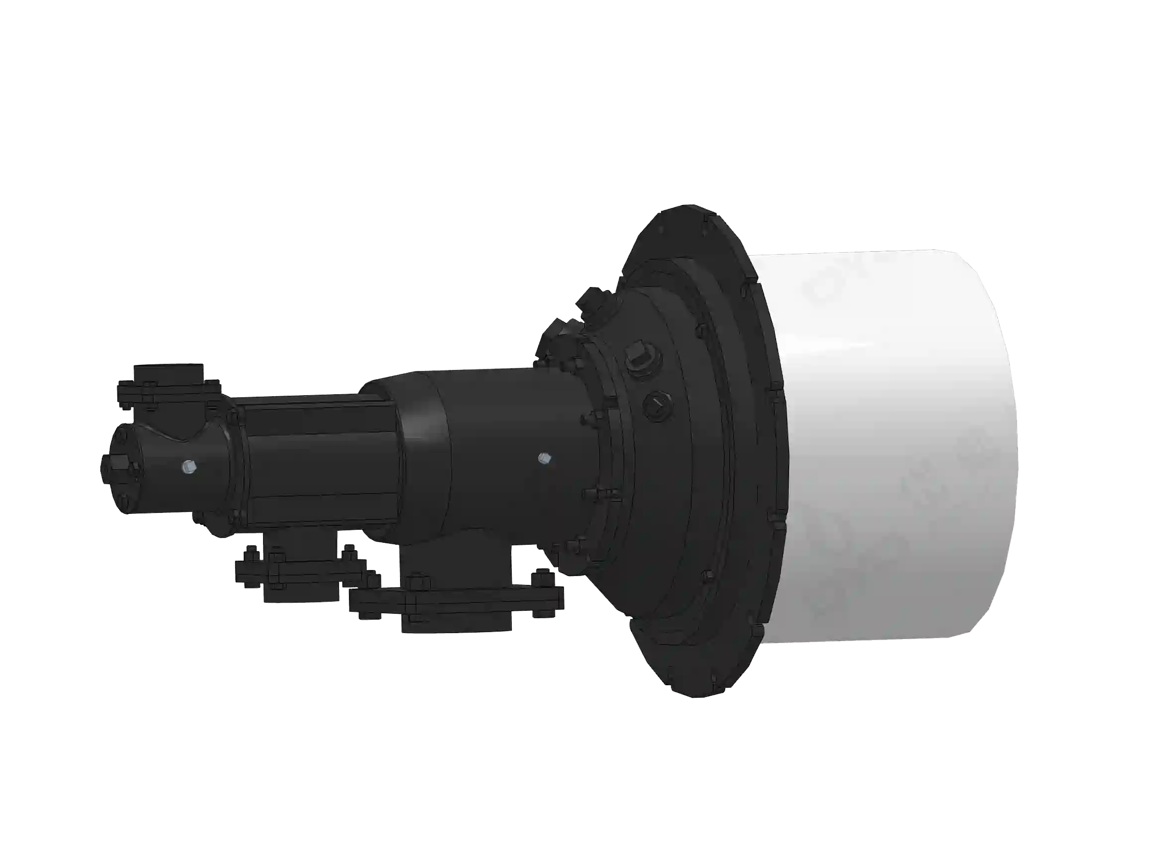
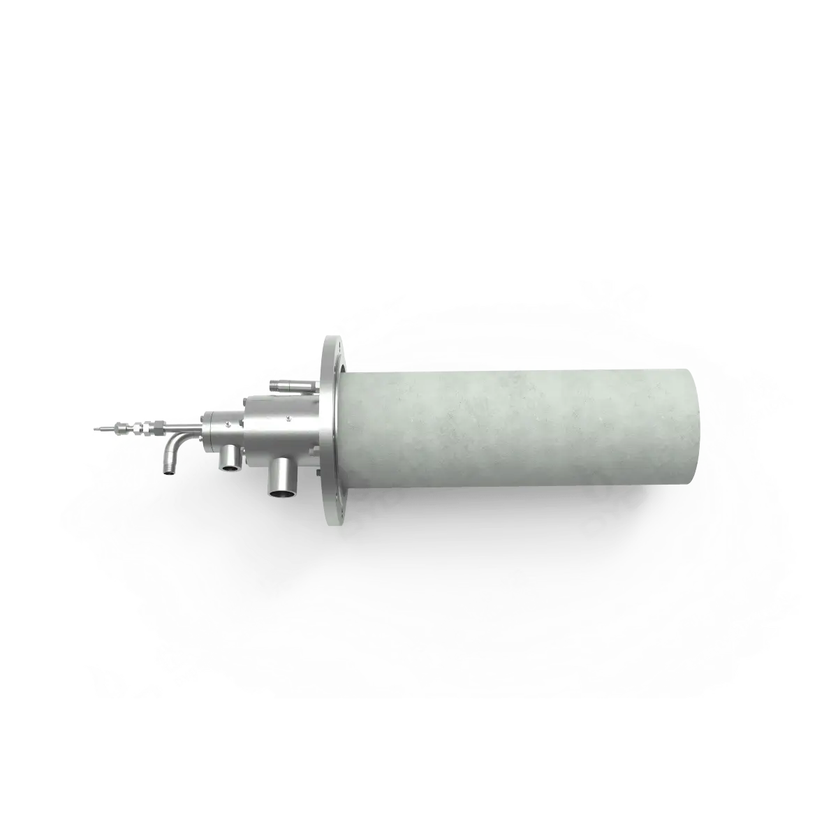
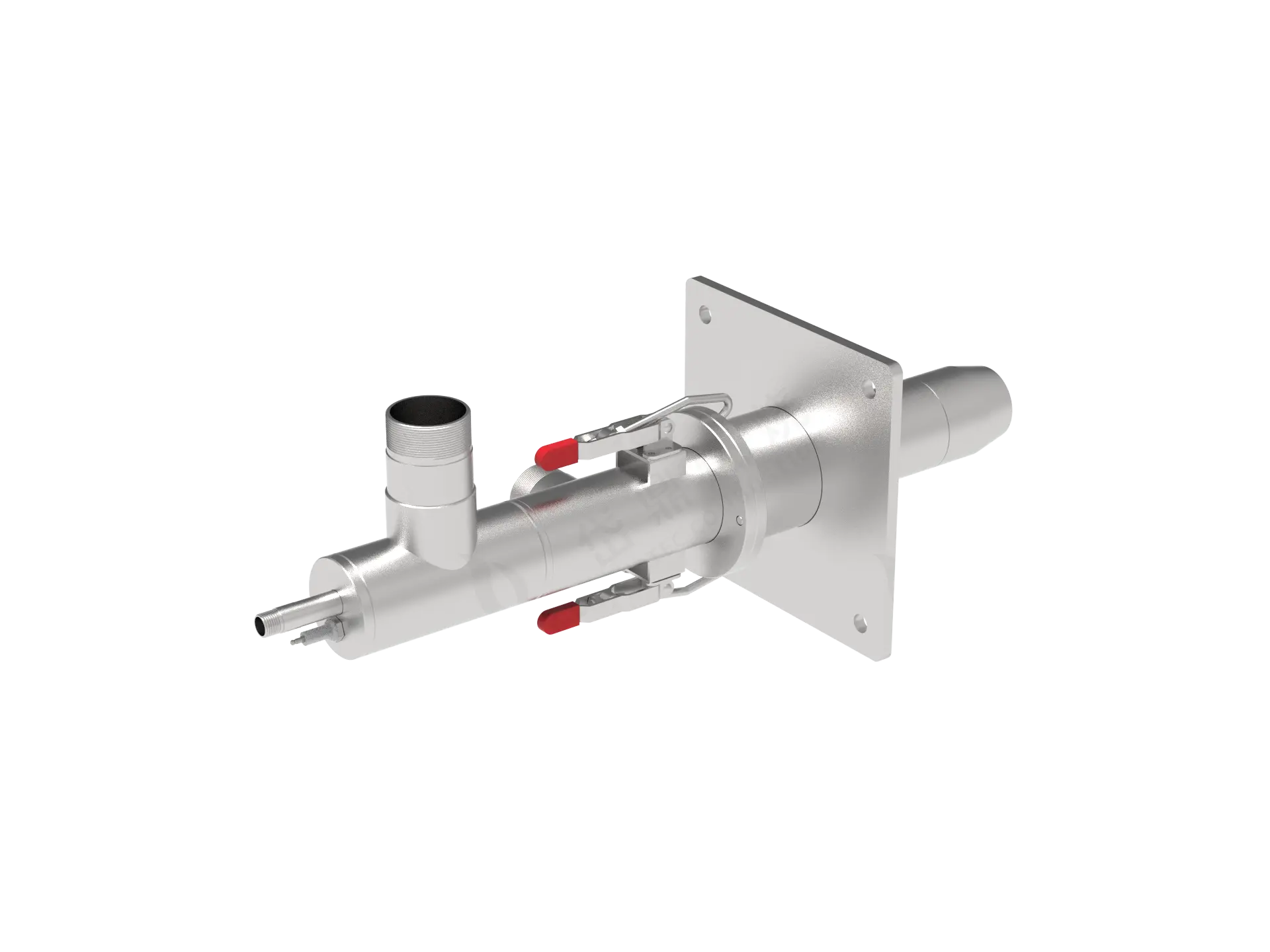
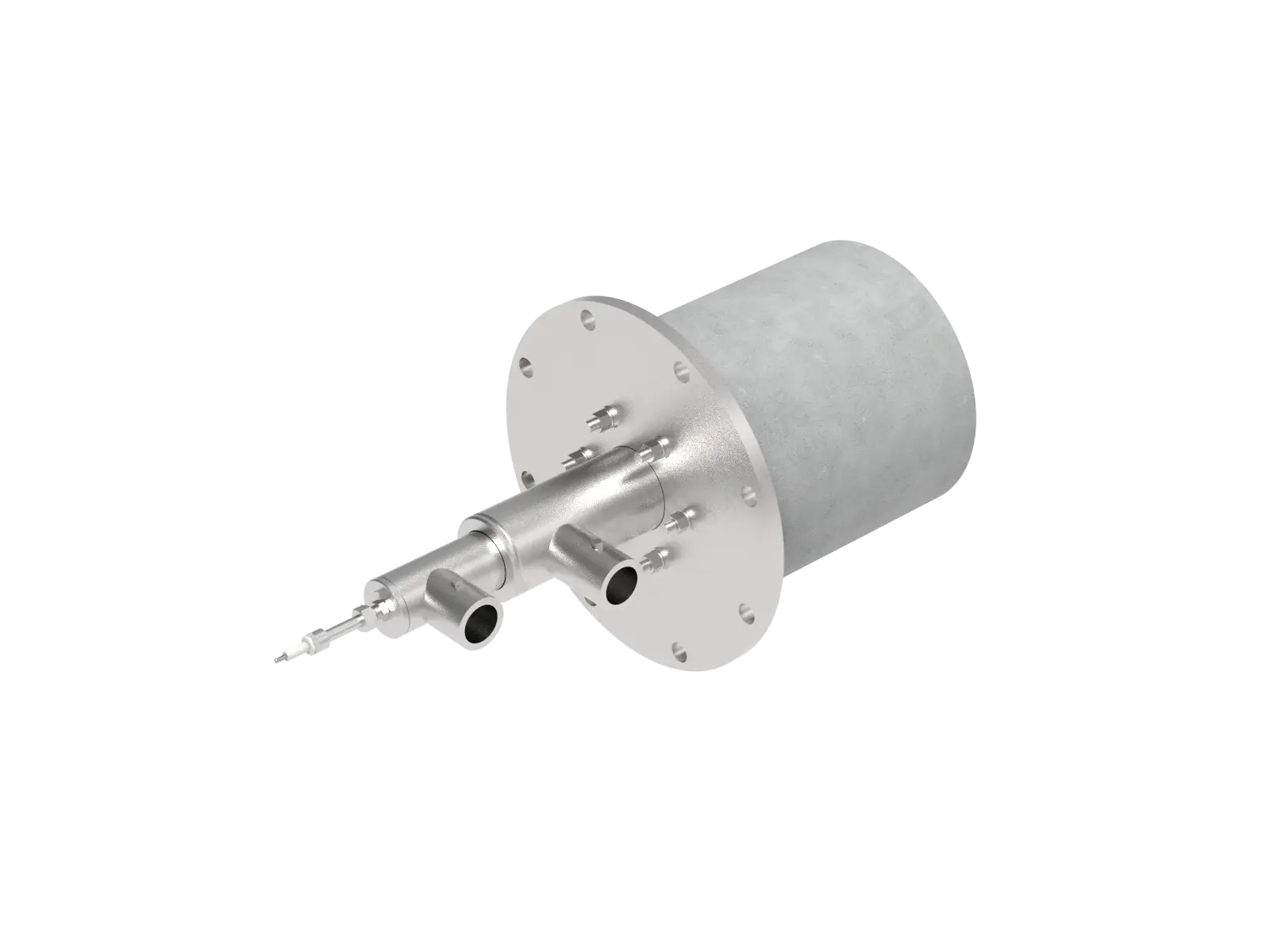
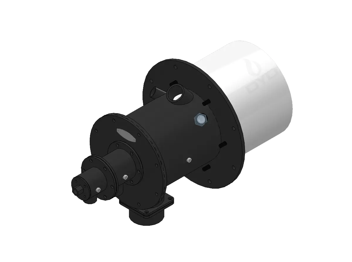
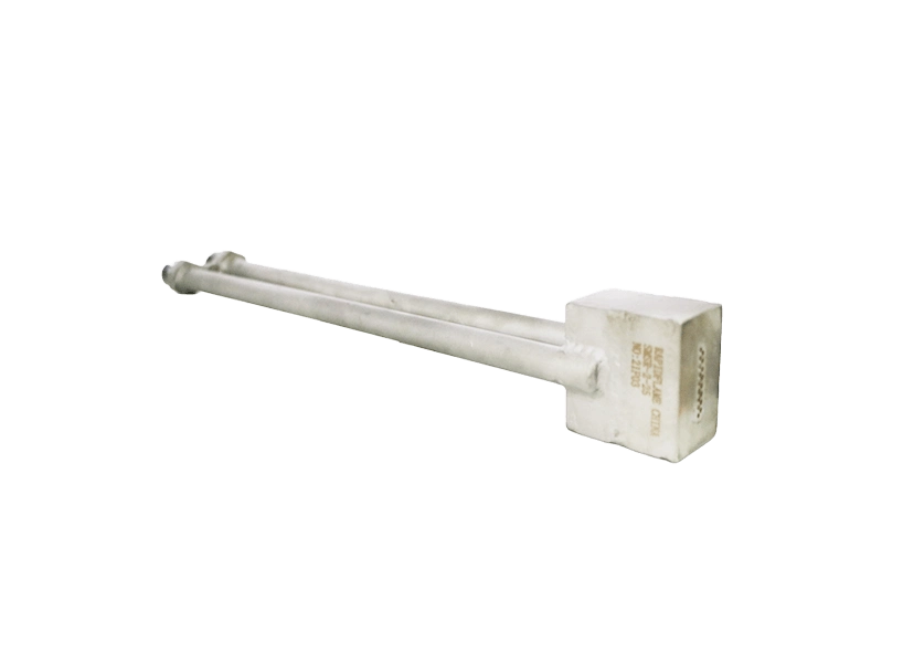
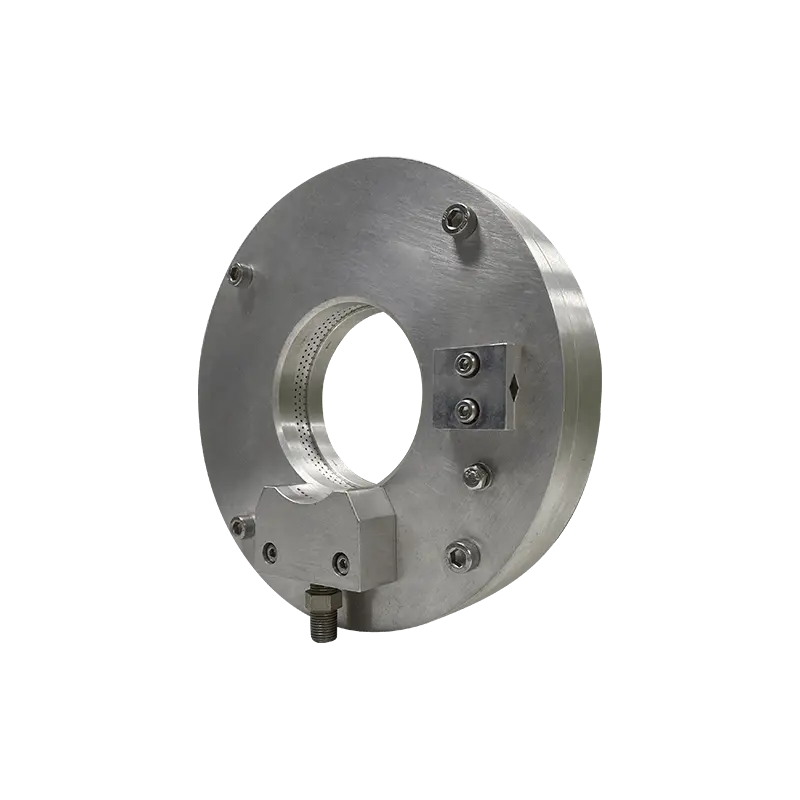
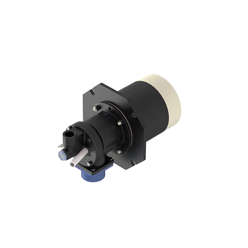
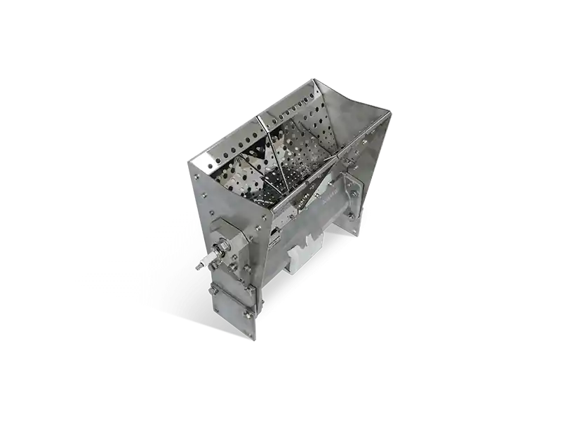
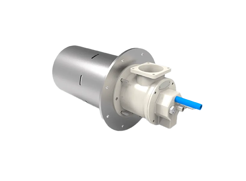
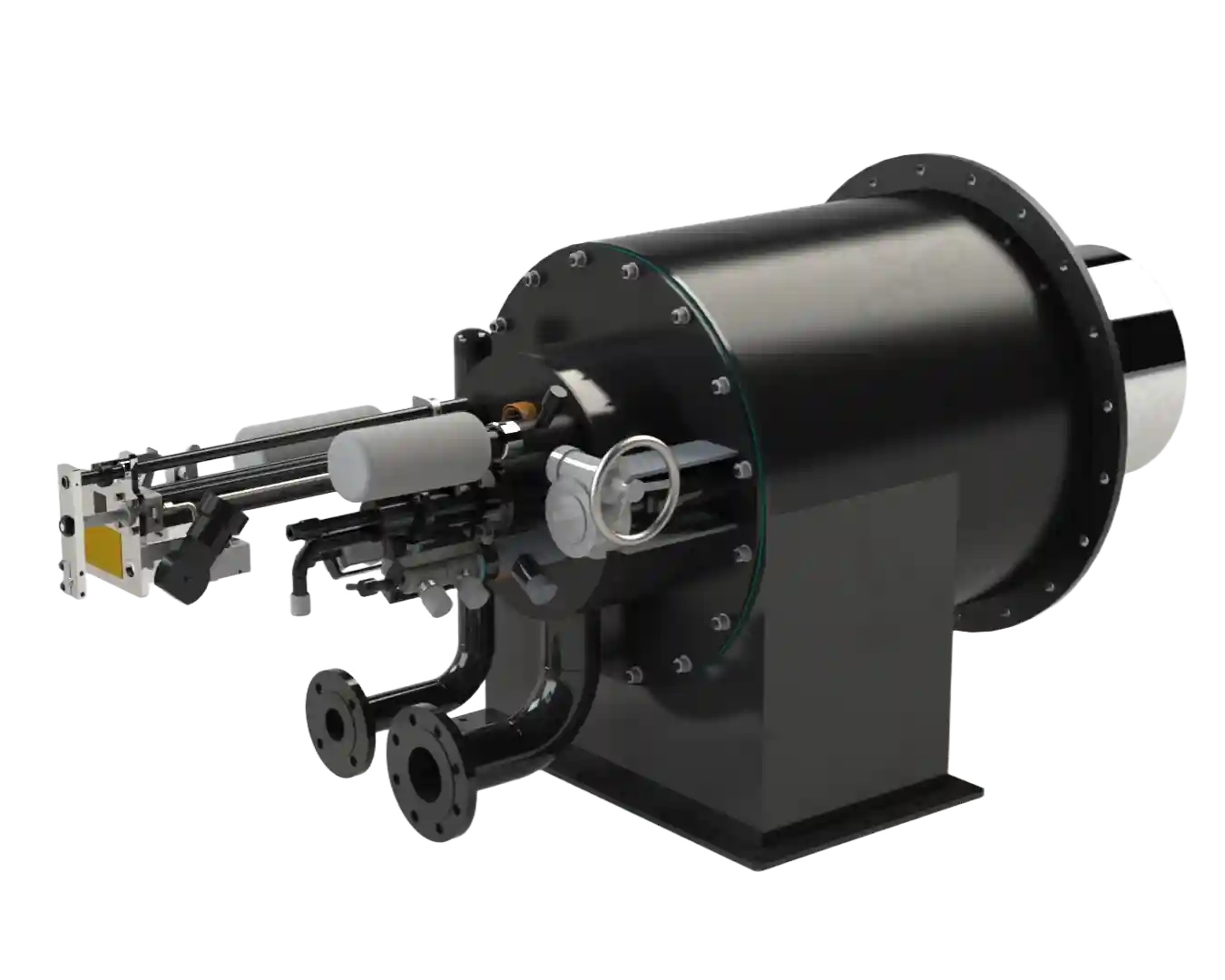
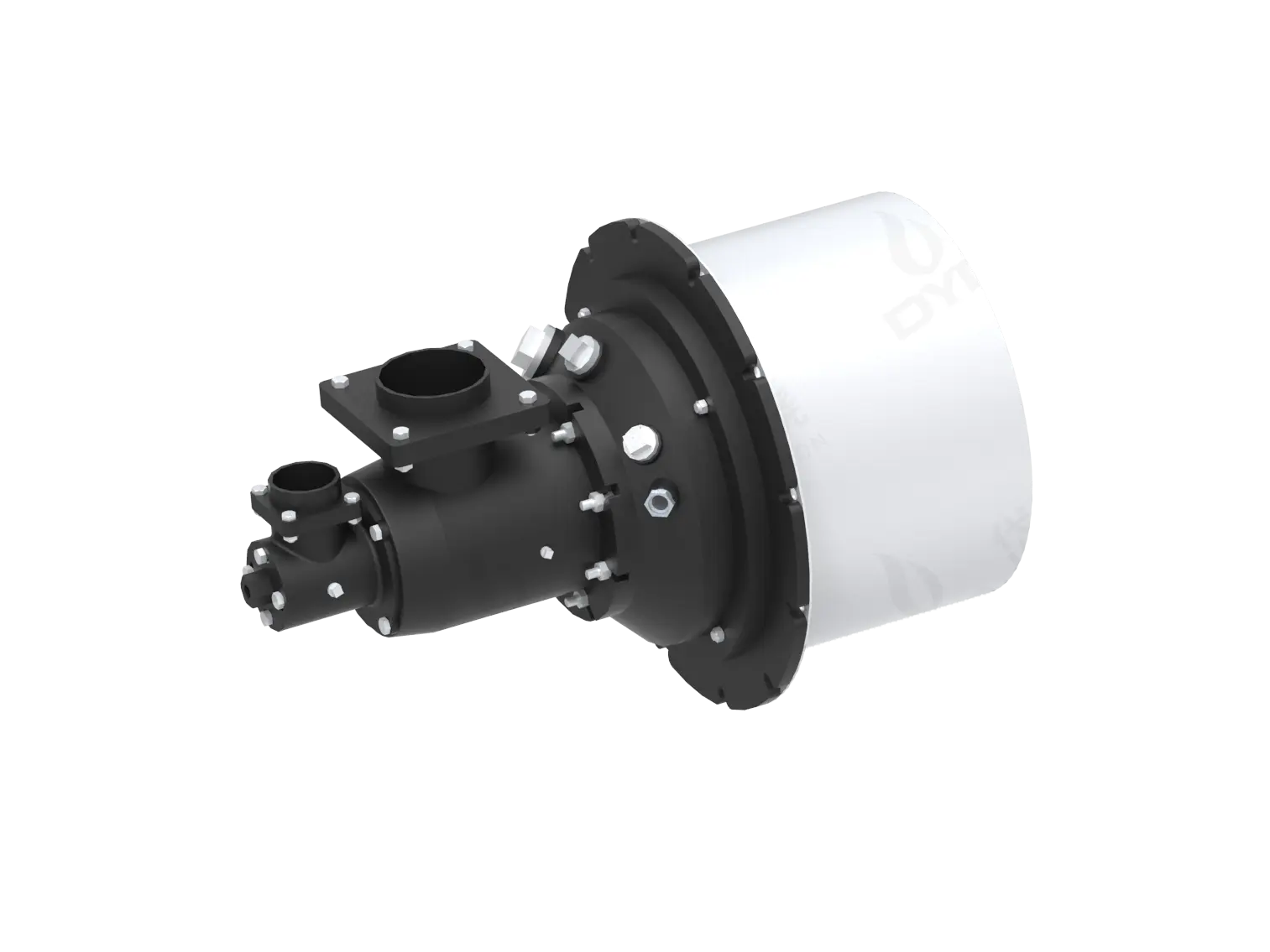
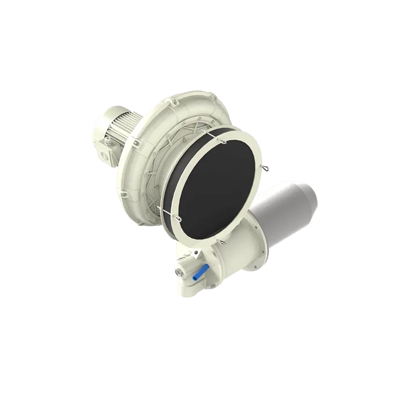
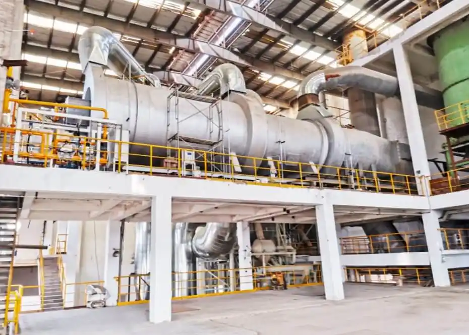
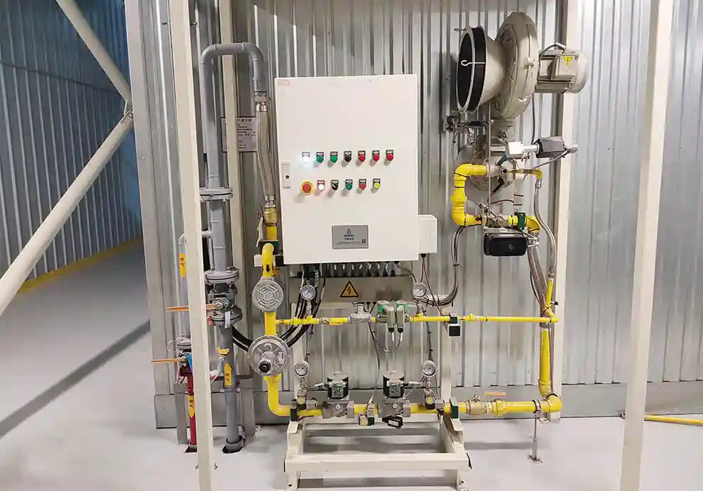
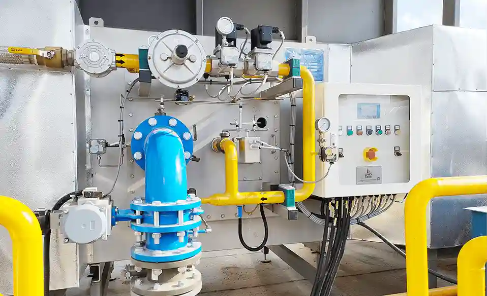
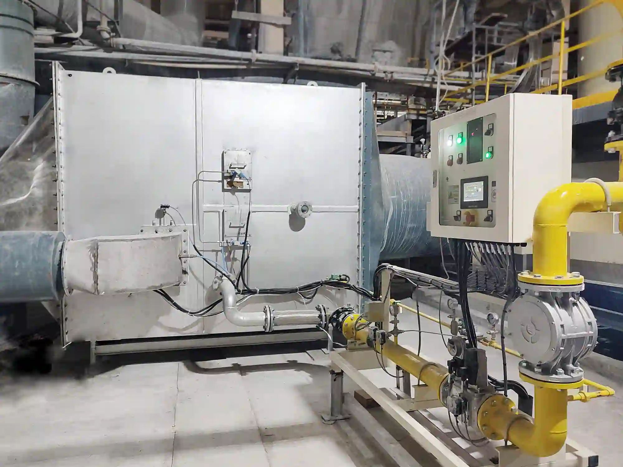
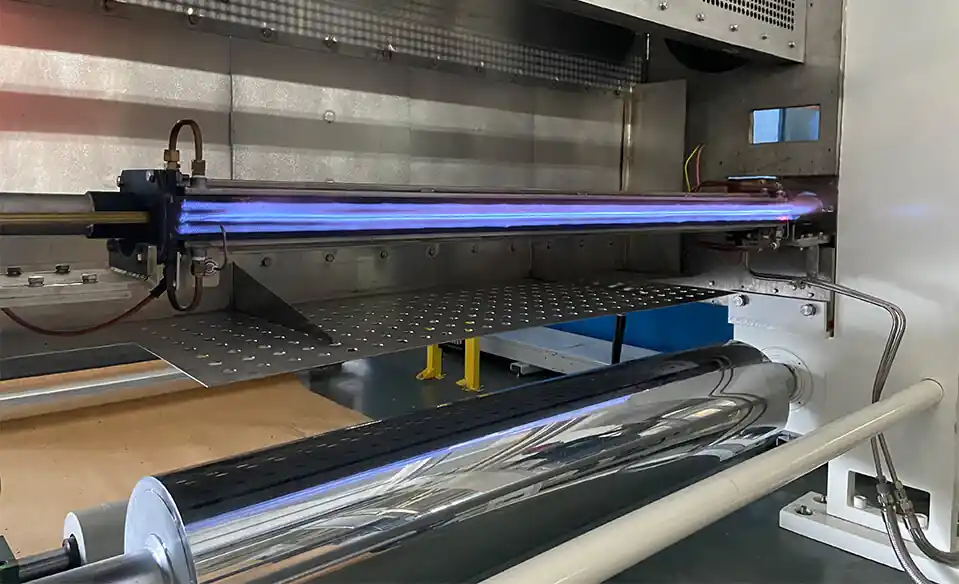
Ignition is the process of initiating combustion by providing enough energy to start the chemical reaction between fuel and oxygen. In industrial burners, ignition is the critical first step that transforms a mixture of fuel and combustion air into a stable flame. It marks the transition from a passive flow of reactants to an active, self-sustaining exothermic reaction that releases thermal energy for the intended process.
A reliable ignition system ensures:
Safe burner startup, preventing hazardous conditions during the critical initiation phase.
Stable flame establishment, allowing the combustion process to proceed smoothly.
Reduced ignition failure, minimizing downtime and the need for repeated startup attempts.
Lower fuel waste, as successful first-time ignition avoids purging and re-purging cycles.
Protection of combustion equipment, preventing damage from delayed ignition or uncontrolled fuel accumulation.
Industrial burners used in furnaces, kilns, dryers, ovens, thermal oxidizers, and heating systems rely on carefully designed ignition processes to achieve repeatable and safe operation. The ignition system is the first line of defense against unsafe combustion conditions and the foundation upon which all subsequent burner performance depends.
Ignition is the moment when the fuel-air mixture reaches the conditions required for combustion to begin. It is a rapid, localized event in which the chemical bonds of fuel molecules are broken and recombined with oxygen atoms, releasing heat and light in the process.
For combustion to occur, three elements are required:
Fuel + Oxygen + Ignition Energy = Combustion
These three elements form the classic "fire triangle." Remove any one of them, and combustion cannot occur. The ignition source provides the initial energy needed to overcome the activation energy barrier of the chemical reaction—the minimum energy threshold that must be surpassed for the exothermic oxidation reaction to proceed.
Once combustion begins, the flame must generate enough heat to sustain itself without continuous external ignition. At this point, the heat released by the reaction raises the temperature of the adjacent unburned mixture to its auto-ignition temperature, creating a self-propagating flame front.
A typical industrial burner ignition process includes several distinct stages, each of which must occur in the correct sequence for safe and reliable startup. These stages are orchestrated by the burner control system, which monitors conditions and actuates valves, fans, and ignition components according to a programmed logic.
Before ignition begins, the burner control system performs a series of safety checks to confirm that all conditions are safe for fuel introduction. This preparation phase is essential for preventing unsafe startup conditions that could lead to equipment damage or personnel injury.
Typical checks include:
Fuel valve status, verifying that main and safety shutoff valves are closed and leak-tight.
Combustion air availability, confirming that the air supply fan is operational and delivering sufficient flow.
Fan operation, checking motor current, speed, and pressure differentials.
Ignition transformer condition, ensuring that the spark generation system is ready.
Flame detector readiness, confirming that the sensor is functional and not producing a false flame signal.
Furnace pressure condition, verifying that the chamber pressure is within acceptable limits for safe ignition.
The purpose is to confirm that the burner can start safely, with all safety interlocks satisfied and no unresolved fault conditions present.
Before fuel is introduced, most industrial burners perform a pre-purge cycle. This is one of the most critical safety steps in the ignition sequence, designed to ensure that the combustion chamber and flue passages are free of any combustible gases that could cause an explosion upon ignition.
During pre-purge:
The combustion air fan operates at full or designated purge flow rate.
Fresh air flows through the furnace, displacing any residual gases from previous operation.
Remaining combustible gases are removed through the exhaust system, rendering the chamber inert.
The duration of the pre-purge is determined by the volume of the furnace and the airflow rate, with typical purges lasting from several seconds to several minutes. Standards such as NFPA 86 and EN 746 specify minimum purge requirements for industrial ovens and furnaces.
The purpose is to:
Prevent explosive fuel accumulation that could result in a deflagration or detonation.
Create safe ignition conditions by establishing an oxidizer-rich atmosphere.
Prepare the combustion chamber thermally by introducing ambient air that will be displaced as the flame establishes.
Pre-purge is one of the most important safety steps in burner operation. Skipping or shortening the purge cycle is a common cause of ignition explosions in poorly maintained or improperly configured systems.
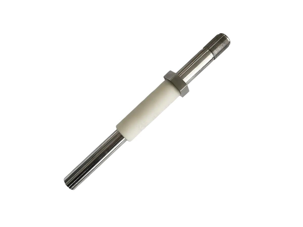
After pre-purge is completed, the ignition system creates an ignition source. This source provides the concentrated energy needed to initiate the chemical reaction at a specific location within the burner head where the fuel-air mixture is present.
Common ignition methods include:
A high-voltage electrical spark jumps between electrodes, typically operating at voltages between 6,000 and 15,000 volts, depending on the design and application. The spark provides a localized, intense source of heat that ignites the surrounding fuel-air mixture.
The spark provides:
High temperature at the electrode gap, exceeding the ignition temperature of the mixture.
Localized ignition energy concentrated at a precise point.
Rapid flame initiation, with ignition occurring within milliseconds of spark generation.
Common applications:
Gas burners of all sizes.
Industrial heating equipment where electrical power is readily available.
Systems requiring fast, repeatable ignition.
A small pilot burner is ignited first, typically by a spark igniter or hot surface. The pilot flame then ignites the main burner fuel stream once the main gas valve opens.
Advantages:
High reliability, as the pilot flame provides a continuous and robust ignition source.
Good ignition stability, particularly in challenging conditions such as high velocities or low temperatures.
Ability to ignite larger burner outputs that may be difficult to ignite directly with a spark.
Common applications:
Large industrial burners where direct spark ignition may be insufficient.
Safety-critical systems where ignition reliability is paramount.
Burners operating with difficult-to-ignite fuels.
An electrically heated element, typically made of silicon carbide or similar high-temperature material, reaches a temperature high enough to ignite the fuel mixture upon contact. The element is heated by electrical resistance and maintained at a controlled temperature.
Advantages:
No moving parts, reducing mechanical failure modes.
Reliable operation with consistent ignition performance.
No spark generation that could interfere with sensitive electronics.
Once the ignition source is active, fuel enters the burner head. This is the moment when the actual ignition event occurs, and careful coordination of fuel delivery and ignition timing is essential.
Inside the burner:
Fuel is injected through the fuel nozzles at the designed pressure and velocity.
Combustion air is supplied through the air passages, meeting the fuel stream.
Fuel and air mix in the region near the ignition source, forming a local mixture within the flammability limits.
Ignition energy from the spark, pilot flame, or hot surface starts the oxidation reaction.
A flame kernel forms—a small, stable combustion zone that serves as the nucleus for full flame development.
The initial flame must grow quickly enough to establish stable combustion. If the flame kernel is quenched by excessive velocity, insufficient residence time, or locally lean conditions, the ignition attempt will fail, and the control system will initiate a safety shutdown.
After ignition, the burner control system must confirm that a stable flame exists. This confirmation is a safety-critical step that ensures fuel will not continue to flow if combustion has not been successfully established.
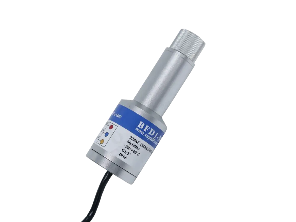
Common flame detection methods include:
Detects ultraviolet radiation produced by the combustion reaction. The sensor responds to the characteristic UV emission from the flame's radical species, providing a fast and reliable indication of combustion.
Advantages:
Fast response, typically within milliseconds.
Suitable for many gas burners, as the flame produces strong UV signatures.
Good discrimination against background radiation from furnace walls.
Measures electrical conductivity through the flame. A voltage is applied across the flame zone, and the ionized gases within the flame provide a conductive path that can be measured as a current signal.
Advantages:
Simple and reliable, with few components.
Common in gas systems, particularly in smaller burners.
Direct indication of flame presence without line-of-sight requirements.
Detects infrared radiation from the flame, typically in specific wavelength bands associated with hot combustion gases.
Advantages:
Suitable for some industrial applications where UV detectors may be less effective.
Can be used in environments where other detection methods are compromised.
If the flame signal is not detected within the required time—typically 2 to 5 seconds depending on the standard—the following occurs:
Fuel valves close immediately, stopping the fuel supply.
Burner shuts down, entering a safe state.
Safety lockout may occur, requiring manual reset before the burner can be restarted.
Starting a burner is more complicated than simply adding fuel and a spark. The industrial combustion environment presents a range of challenges that can make ignition difficult under certain conditions.
Successful ignition depends on a delicate balance of many interrelated factors:
Fuel concentration, which must be within the flammability limits at the ignition point.
Air-fuel ratio, requiring the correct stoichiometric balance for the specific fuel.
Ignition energy, sufficient to raise the local mixture above its ignition temperature.
Mixing quality, ensuring that the fuel and air are well blended in the ignition zone.
Burner geometry, providing the correct flow conditions at the ignition location.
Furnace temperature, as cold equipment may require more ignition energy.
Pressure conditions, with low or fluctuating pressures affecting mixture stability.
The mixture must be within the flammability range—the range of fuel concentrations in air that can support combustion. Outside this range, ignition is either impossible (too lean) or incomplete (too rich).
Problems:
Oxygen shortage, as insufficient oxidizer is available for complete combustion.
Slow ignition, as the excess fuel must diffuse and find oxygen before ignition can occur.
Smoke formation, with soot particles generated in the fuel-rich environment.
Problems:
Weak mixture that cannot sustain the combustion reaction.
Difficult flame formation, as the heat release is diluted by excess nitrogen.
Ignition failure, when the mixture is below the lower flammable limit.
The burner must create the correct mixture near the ignition point, where the local equivalence ratio is within the range that supports reliable ignition.
The ignition source must provide sufficient energy to overcome the activation energy of the combustion reaction. The required energy depends on the fuel, the mixture strength, and the local flow conditions.
Insufficient ignition energy may cause:
Delayed ignition, with the flame kernel forming slowly and potentially failing to establish.
Flame failure, as the initial reaction extinguishes before propagating.
Repeated startup attempts, increasing system wear and fuel waste.
Industrial burners often use high-energy ignition systems—with spark energies of several joules—to ensure reliable startup under the full range of operating conditions.
Different fuels require different ignition strategies because their chemical and physical properties influence how readily they ignite and how stable the resulting flame will be.
Characteristics:
Easy ignition, with a wide flammability range and low ignition energy requirement.
Clean combustion with minimal soot or residue formation.
Widely used in industrial burners across all applications.
Characteristics:
Higher flame speed, requiring careful control to avoid flashback.
Different ignition behavior, with a broader flammability range but lower minimum ignition energy.
Require careful flame control and sometimes specialized burner designs.
Require:
Atomization, breaking the liquid into fine droplets to increase surface area.
Proper droplet size, ensuring that droplets can vaporize before ignition.
Adequate vaporization, as ignition occurs in the vapor phase, not in the liquid state.
Before ignition can occur, the liquid fuel must be converted into a flammable vapor that can mix with air and support a flame.
The burner head strongly affects ignition quality by defining the aerodynamic conditions at the point of ignition. The placement of the igniter relative to the fuel and air streams is a critical design parameter.
A good burner head provides:
Stable fuel-air mixing in the ignition zone, ensuring a flammable mixture is present.
Correct ignition location, placing the spark or pilot flame where the mixture is optimal.
Flame anchoring once ignition occurs, enabling the flame to grow and stabilize.
Reliable flame propagation, allowing the flame to spread from the ignition point to the full burner cross-section.
Poor burner head design can cause:
Ignition delay, as the mixture is not optimally positioned for ignition.
Flame instability, with the flame failing to anchor after ignition.
Flame blow-off, where the established flame cannot sustain itself against the flow velocity.
The surrounding furnace environment also affects ignition through its influence on the fuel-air mixture and the flame development process.
Important factors include:
Furnace pressure, with excessive negative pressure pulling the flame away from the ignition point.
Temperature, with cold furnace surfaces potentially quenching the flame kernel before it can establish.
Residual gases, which may dilute the mixture or alter its flammability.
Air leakage, which can change the local air-fuel ratio near the igniter.
For example, a cold furnace may require stronger ignition support than a hot furnace already operating at temperature, as the cold surfaces absorb heat from the flame kernel and slow its growth.
A typical sequence follows a logical progression from standby to normal operation:
The burner receives a start signal from the controller or operator, initiating the startup sequence.
↓
Control system verifies that all safety interlocks are satisfied and that no fault conditions exist.
↓
Air fan operates to purge the furnace and exhaust passages of any residual combustibles.
↓
Spark generation begins, or the pilot flame is initiated through its own ignition source.
↓
If used, the pilot flame is established and proven stable.
↓
The main gas valve opens, admitting fuel to the burner head where it mixes with combustion air.
↓
Flame detector verifies that combustion has been successfully established and that a stable flame is present.
↓
Burner modulates fuel and air according to process demand, with the ignition source typically deactivated after flame confirmation.
| Problem | Possible Cause |
|---|---|
| No ignition | Faulty igniter, insufficient fuel, poor mixture at ignition point |
| Delayed ignition | Incorrect air-fuel ratio, weak ignition energy, cold furnace conditions |
| Flame failure after ignition | Poor flame stability, detector issue, insufficient flame anchoring |
| Ignition explosion | Insufficient purge, fuel accumulation during pre-ignition |
| Repeated shutdown | Flame signal loss, control system errors, improper sensor positioning |
Regularly inspect and service all components of the ignition system to ensure consistent performance:
Ignition electrodes, checking for wear, erosion, and proper gap setting.
Ignition cables, looking for insulation damage or high-resistance connections.
Transformers, verifying output voltage and current.
Pilot burners, ensuring clean operation and proper flame shape.
Proper tuning of the burner reduces the likelihood of ignition difficulties:
Fuel pressure, set to the correct value for the application and load.
Air pressure, ensuring the correct air-fuel ratio at the ignition point.
Ignition position, with the igniter correctly located relative to the fuel and air streams.
Flame appearance, used as a visual check during commissioning and periodic testing.
A correct purge cycle improves both safety and ignition reliability:
Safety, by removing any residual combustibles.
Ignition reliability, by establishing a consistent starting atmosphere.
Combustion stability, by ensuring that the chamber is properly ventilated.
A suitable flame detector prevents false shutdowns and unsafe fuel release:
Proper sensor selection for the fuel type and application.
Correct positioning for reliable flame viewing.
Regular calibration and testing to maintain sensitivity.
Ignition and stable combustion are related but distinct aspects of burner operation. A successful ignition does not guarantee stable combustion.
Ignition:
The process of starting combustion, typically completed within a few seconds. It requires sufficient energy to initiate the reaction and establish a flame kernel.
Flame Stability:
The ability of the flame to continue burning after ignition and to remain anchored at the burner under varying operating conditions. Stability depends on the balance between flow velocity, flame speed, and recirculation.
A burner may ignite successfully but still experience flame lift-off, oscillation, or extinction if combustion conditions are not properly controlled after ignition.
The combustion process starts when an ignition source, such as a spark, pilot flame, or hot surface, provides enough energy to ignite the fuel-air mixture. The ignition energy raises the local temperature above the auto-ignition temperature of the fuel, initiating the exothermic oxidation reaction.
Pre-purge removes leftover combustible gases from the furnace to prevent unsafe fuel accumulation and possible explosions. It ensures that the chamber atmosphere is non-flammable before any fuel is introduced for ignition.
This usually happens when the flame detector cannot confirm a stable flame within the required time window or when combustion conditions are unstable, causing the flame to extinguish shortly after establishment. Possible causes include incorrect air-fuel ratio, poor flame anchoring, or detector malfunction.
Ignition time depends on burner design, fuel type, and control system. Industrial burners typically complete ignition within seconds after the purge sequence, with most standard systems achieving flame establishment within 2 to 5 seconds of fuel introduction.
Yes. If fuel and air are not properly mixed, the ignition source may not be able to establish a stable flame. Poor mixing can create localized zones where the mixture is outside the flammability limits, preventing ignition or causing weak, unstable combustion.
Ignition is the foundation of safe and reliable industrial combustion. It is not simply the creation of a spark; it is a carefully controlled process involving fuel supply, air management, ignition energy, flame detection, and safety control. Each step must occur in the correct sequence and under the right conditions to ensure a successful startup.
A successful ignition system ensures:
Reliable burner startup on the first attempt and under all operating conditions.
Stable flame formation that transitions smoothly to normal combustion.
Safe operation through rigorous purge and detection protocols.
Efficient combustion by establishing the flame correctly from the outset.
For modern industrial burners, ignition performance depends on the combined design of the ignition system, burner head, fuel-air mixing process, and combustion control system. Each element must be properly engineered and maintained to achieve the reliability that industrial processes demand.
DYDTEC Combustion specializes in industrial burner technology, combustion systems, and customized thermal solutions. The company provides industrial burner solutions for furnaces, drying equipment, thermal processing systems, and energy-efficient heating applications, focusing on reliable ignition systems, optimized combustion performance, stable flame control, low emissions, and long-term operational reliability. With extensive experience in ignition system design and combustion safety engineering, DYDTEC supports customers in achieving consistent, safe, and efficient burner startup across a wide range of industrial applications.