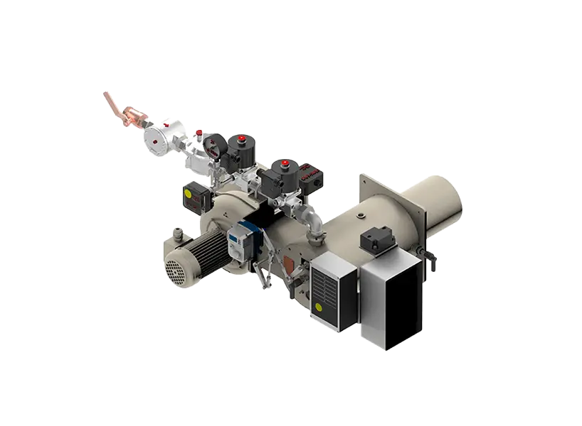
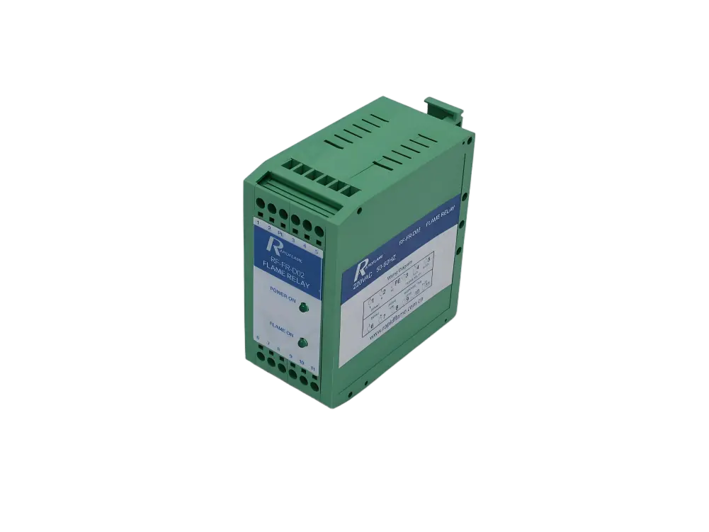
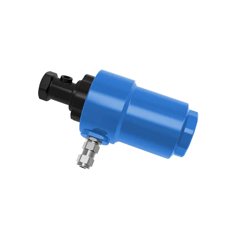
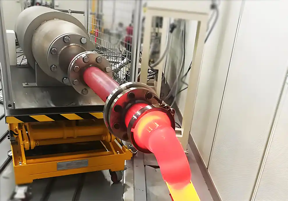
Flame detection is a critical safety and control function in industrial combustion systems. It confirms whether a burner flame is present and stable after ignition. Without reliable flame detection, fuel could continue flowing into a furnace without combustion, creating a serious risk of fuel accumulation and potential explosion. This makes flame detection not merely a performance enhancement but a fundamental safety requirement for any automated combustion equipment.
In industrial burners, flame detection systems are responsible for:
Confirming successful ignition, verifying that the transition from spark to stable flame has occurred.
Monitoring continuous flame operation throughout the firing cycle.
Shutting off fuel during flame failure, preventing unsafe fuel release.
Improving combustion safety by providing the primary safeguard against uncontrolled fuel flow.
Supporting automatic burner control by providing real-time feedback to the control system.
Flame detection technology is widely used in industrial furnaces, kilns, dryers, boilers, thermal oxidizers, and other combustion equipment. In each of these applications, reliable flame monitoring is essential for protecting personnel, equipment, and the process itself from the consequences of combustion interruptions.
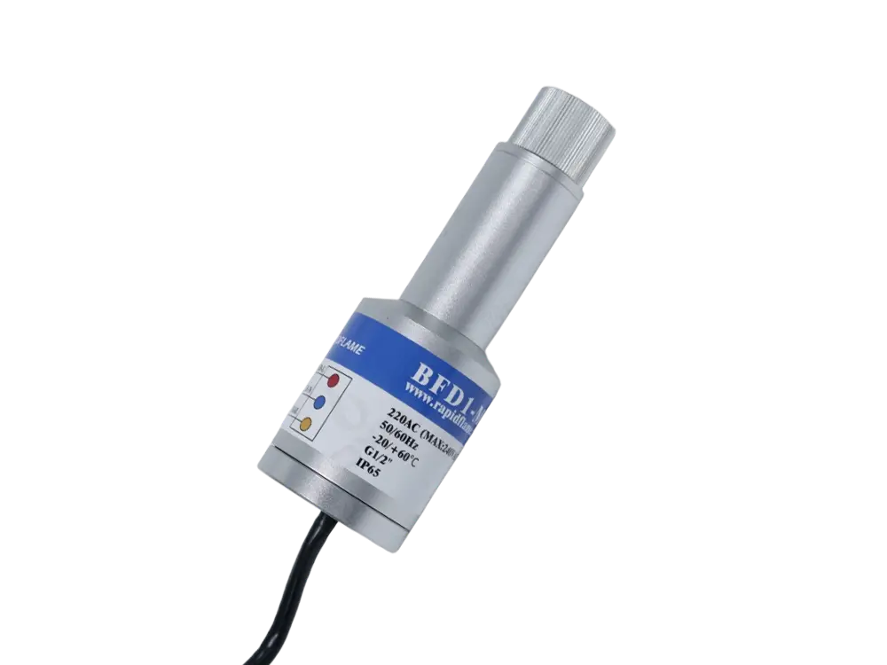
Flame detection is the process of identifying the presence of a combustion flame using sensors that detect physical signals generated during combustion. It is the means by which the burner control system "knows" that fuel is actually burning and that the combustion reaction is proceeding as intended.
A flame produces several detectable characteristics that can be measured and interpreted:
Ultraviolet (UV) radiation emitted by excited molecular species in the flame zone.
Infrared (IR) radiation generated by hot combustion gases and radiating soot particles.
Visible light in the spectrum detectable by the human eye.
Electrical conductivity due to the presence of ions and free electrons in the flame.
Flame flicker frequency, the natural fluctuation pattern that characterizes active combustion.
Flame detectors convert these signals into electrical feedback for the burner control system. The sensor output is processed, compared against thresholds, and used to determine whether combustion is occurring.
The basic process is:
Flame → Sensor Detection → Signal Processing → Burner Controller → Fuel Control
This closed-loop arrangement ensures that fuel is supplied only when a valid flame signal is present. If the flame disappears unexpectedly, the control system immediately closes the fuel valves to prevent unsafe fuel release, typically within a few seconds or less depending on the safety standard and application.
A burner cannot rely only on the ignition system to confirm combustion. The ignition source is typically deactivated after the flame is established, and from that point forward, the flame must sustain itself.
A spark or pilot flame may start correctly, but the main flame could:
Fail to establish if the fuel-air mixture is not within ignitable limits.
Become unstable due to changes in fuel composition, air supply, or furnace pressure.
Blow out during operation as a result of excessive draft, load changes, or other disturbances.
Without flame detection, the burner may continue supplying fuel without combustion. This condition allows unburned fuel to accumulate in the furnace, creating an explosive atmosphere that can ignite catastrophically when the flame eventually re-establishes or when a hot surface provides ignition energy.
A reliable flame detection system provides:
Safety protection, preventing the accumulation of unburned fuel and the risk of deflagration.
Automatic shutdown, ensuring immediate fuel cut-off when the flame is lost.
Stable operation, by enabling the control system to respond to combustion variations.
Reduced risk of explosions, which is the ultimate objective of any combustion safety system.
A typical flame detection process includes several stages, each of which must function correctly for reliable monitoring.
During combustion, the chemical reactions between fuel and oxygen produce various forms of energy release, including electromagnetic radiation across a broad spectrum. These physical signals are the raw data that flame detectors rely upon.
The most common signals include:
Produced by high-energy combustion reactions, specifically by the emission from excited radicals such as OH, CH, and C₂ in the flame front. UV radiation is strongly absorbed by glass and air, so detectors require specialized materials such as quartz or sapphire windows.
Generated by hot combustion gases and radiating soot particles. IR signals are particularly strong from flames containing carbonaceous materials and from the hot CO₂ and H₂O present in all combustion products.
Created because flames contain electrically conductive particles—ions and free electrons generated by the high-temperature dissociation of gas molecules. When an electric field is applied across the flame zone, a measurable current flows.
The natural intensity variation of flames over time, typically in the range of 10 to 100 Hz depending on the flame type and burner design. This flicker is a characteristic signature of active combustion.
The flame detector is positioned near the burner head and observes the flame zone through a viewing port or directly within the burner assembly. The physical placement of the detector is critical to its ability to capture a reliable signal.
The detector must be installed correctly to ensure it can:
See the flame clearly, with an unobstructed line of sight to the combustion zone.
Avoid interference from hot furnace walls, refractory surfaces, or other heat sources that could produce false signals.
Respond quickly, positioning the sensor close enough to detect signal changes without time lag.
Installation factors include:
Viewing angle, ensuring that the detector observes the flame root rather than just the outer flame envelope.
Distance from flame, which affects signal strength and response time.
Furnace geometry, which may require specialized sight tubes or purged viewing ports.
Burner arrangement, with multiple burners requiring individual detection channels.
The detector analyzes the received signal and converts it into a form that the burner control system can interpret. This processing stage is essential for distinguishing between a valid flame signal and background noise or interference.
The control system determines:
Flame present—the signal meets the threshold for active combustion.
Flame stable—the signal remains consistent without excessive fluctuation.
Flame lost—the signal falls below the threshold for a specified time period.
If the signal meets the required conditions, the burner continues operation. If the signal disappears or falls below the acceptable level, the fuel valves close immediately and a safety shutdown is initiated.
UV flame detectors sense ultraviolet radiation produced by combustion reactions, typically in the 200 to 300 nanometer wavelength range. The sensor is usually a UV-sensitive phototube or solid-state device that generates a current proportional to the incident UV intensity.
Fast response, with detection times typically measured in milliseconds.
High sensitivity to the specific UV wavelengths associated with flames.
Suitable for gas flames where UV emission is strong.
Commonly used in industrial gas burners, furnaces, and thermal processing systems where quick, reliable detection is required.
May be affected by strong UV sources such as welding arcs or other artificial UV emitters. Additionally, UV radiation is attenuated by smoke, dust, and fouling of the viewing window, requiring regular cleaning and maintenance.
IR detectors sense infrared radiation from hot flame gases, typically in the 3 to 5 micron or 1 to 2 micron wavelength ranges. The sensor responds to the thermal emission of combustion products and, in many cases, to the glowing soot particles that are characteristic of diffusion flames.
Suitable for high-temperature environments where UV detectors may be less effective.
Good long-distance detection capability, as IR radiation is less attenuated by atmospheric absorption.
Used in large industrial burners and heavy-duty combustion systems where detectors must be positioned further from the flame.
May require careful adjustment to avoid detecting unrelated heat sources such as hot furnace walls, refractory materials, or adjacent flames.
Many advanced industrial systems combine UV and infrared detection into a single sensor head or use separate sensors with combined logic.
Advantages:
Higher reliability, as both sensors must detect flame for confirmation.
Better discrimination between flame and background radiation, reducing false positives.
Reduced false signals, as spurious sources that trigger one sensor but not the other are rejected.
Common applications include large furnaces, critical industrial processes, and systems where safety integrity levels demand redundant sensing.
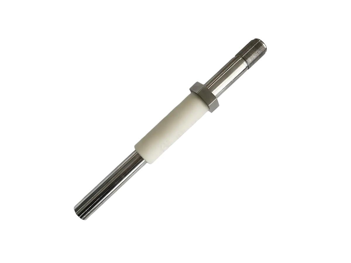
A flame contains ions that allow a small electrical current to flow between electrodes placed in or near the flame zone. A voltage is applied across the electrodes, and the current is measured. The presence of a conductive flame completes the circuit, while the absence of flame results in no current.
Advantages:
Simple structure with few components.
Fast response to flame presence or loss.
Low cost, making it suitable for smaller burner applications.
Common applications include gas burners, compact combustion equipment, and systems where simplicity and reliability are paramount.
Limitations:
Requires conductive flame characteristics—not all flames produce sufficient ionization for reliable detection.
More sensitive to installation conditions, including electrode positioning and gap spacing.
May be affected by flame temperature, composition, and stability.
A typical burner sequence integrates flame detection at multiple points to ensure safe startup and operation:
The burner receives an operating signal from the controller or operator, initiating the startup sequence.
↓
The combustion chamber is cleared of residual gases through the pre-purge cycle, creating a safe atmosphere for ignition.
↓
Spark or pilot flame starts the combustion process, introducing the fuel-air mixture.
↓
The detector confirms that a stable flame has been established within the required time window, typically 2 to 5 seconds. If confirmed, the main fuel valves remain open.
↓
The burner continues to fire, with the flame detector continuously monitoring the combustion zone.
↓
The detector constantly checks flame presence and stability, providing real-time feedback to the control system.
↓
If the flame disappears at any point, the fuel valves close immediately, the burner shuts down, and an alarm is activated to alert operators.
Incorrect positioning is one of the most common causes of flame detection problems. The detector must have an unobstructed view of the flame root—the region where combustion is first established—rather than the later stages of the flame where signals may be weaker.
Incorrect positioning can cause:
Weak flame signal, making detection marginal.
False shutdowns, as the detector fails to see the flame even when combustion is occurring.
Poor reliability, with intermittent detection that compromises burner operation.
Different flames produce different detection signals. The type of fuel, burner design, and operating conditions all influence the strength and nature of the signal available for detection.
Factors include:
Fuel type, with natural gas, hydrogen, oil, and solid fuels all producing different emission spectra.
Flame temperature, affecting the intensity and wavelength distribution of radiation.
Flame shape, which changes the spatial distribution of the signal.
Burner design, with some burners producing more intense UV or IR signals than others.
The furnace environment can interfere with flame detection in several ways.
Possible interference includes:
Hot furnace walls, which can emit IR radiation that resembles flame signals.
Reflected radiation from the flame bouncing off furnace surfaces.
Smoke and particulate matter that attenuate UV and visible signals.
Dust accumulation on detector windows, reducing sensitivity.
Exhaust gases and moisture that can condense on optical surfaces.
Dirty or damaged detectors are a major source of flame detection failures. Over time, optical surfaces become coated with dust, soot, or chemical deposits that reduce signal transmission.
Poor maintenance may cause:
Weak signals, as light transmission is reduced.
False alarms, when the control system cannot interpret the degraded signal.
Unexpected burner shutdowns, resulting from marginal detection performance.
Regular inspection and cleaning are essential for reliable operation.
Possible causes:
Incorrect detector alignment, with the sensor not properly aimed at the flame root.
Dirty sensor lens or viewing window, blocking signal transmission.
Weak flame signal, resulting from low flame intensity or poor fuel-air mixing.
Incorrect sensitivity setting, with the threshold set above the actual signal level.
Solutions:
Clean the detector and viewing port.
Adjust detector position for optimal flame viewing.
Check flame quality and optimize burner tuning.
Recalibrate sensitivity settings.
Possible causes:
Radiation from hot furnace surfaces, particularly refractory walls.
Electrical interference from ignition systems or other equipment.
Incorrect detector type selected for the application.
Solutions:
Improve installation to shield the detector from background radiation.
Use UV/IR combined detection for better discrimination.
Adjust signal processing parameters to reject false sources.
Possible causes:
Unstable flame conditions causing intermittent signal loss.
Poor mixing leading to flame fluctuation.
Pressure fluctuations in the furnace or fuel supply.
Detector failure or degradation.
Solutions:
Check and optimize combustion conditions.
Inspect burner adjustment and fuel-air ratio.
Test detector function and replace if necessary.
Review operating parameters for changes that may affect flame stability.
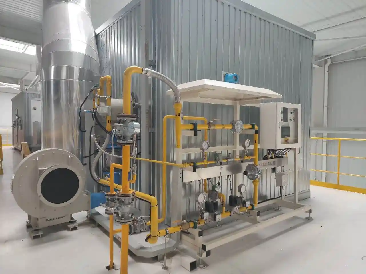
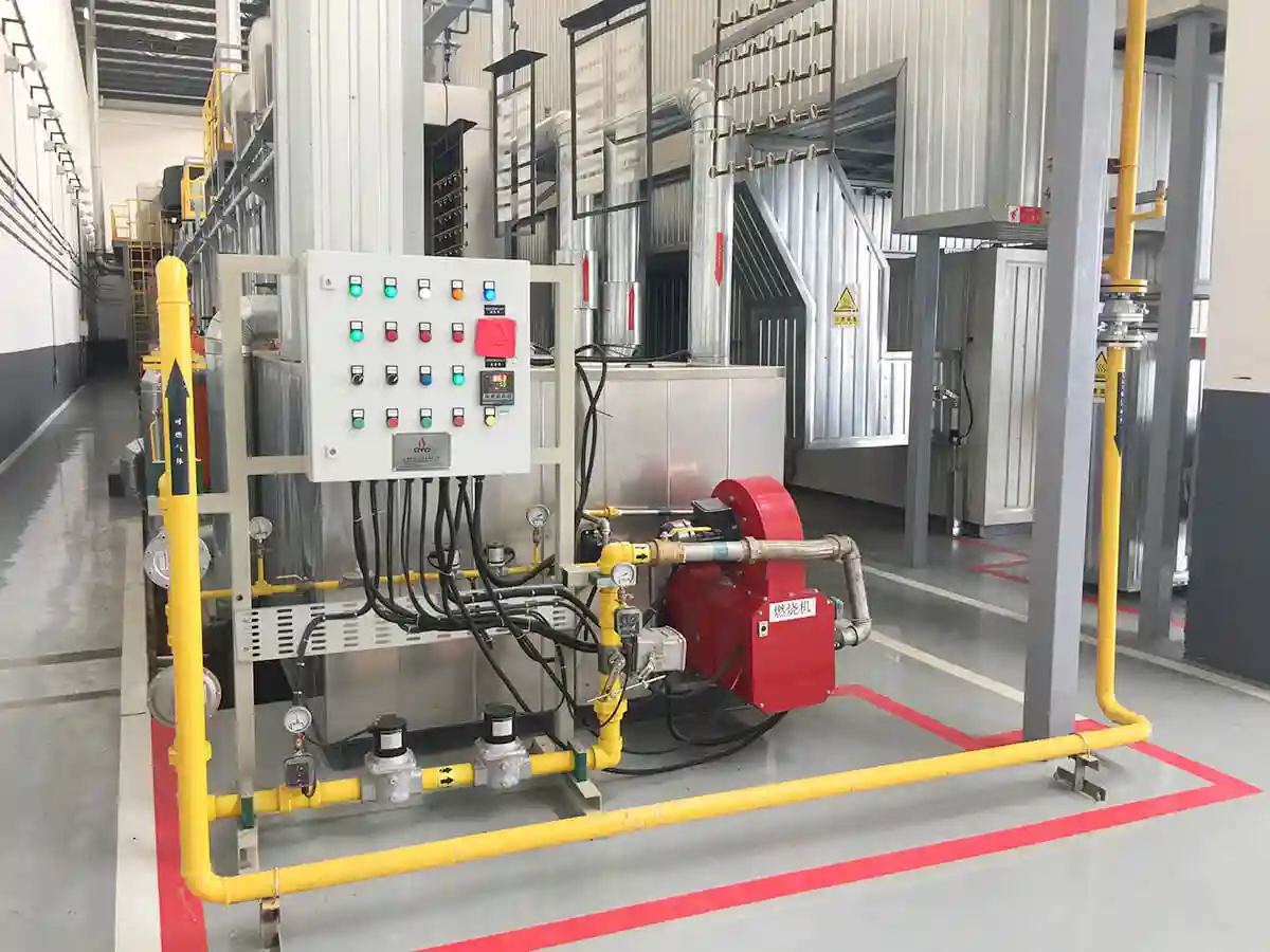
Modern industrial burners use flame detectors together with a comprehensive safety system that includes multiple layers of protection. The flame detector is a key input to this safety chain.
Components include:
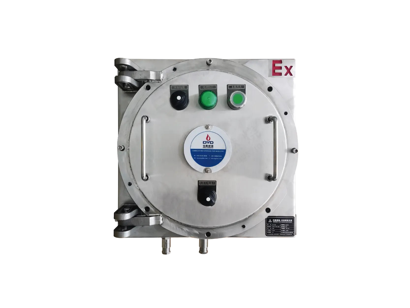
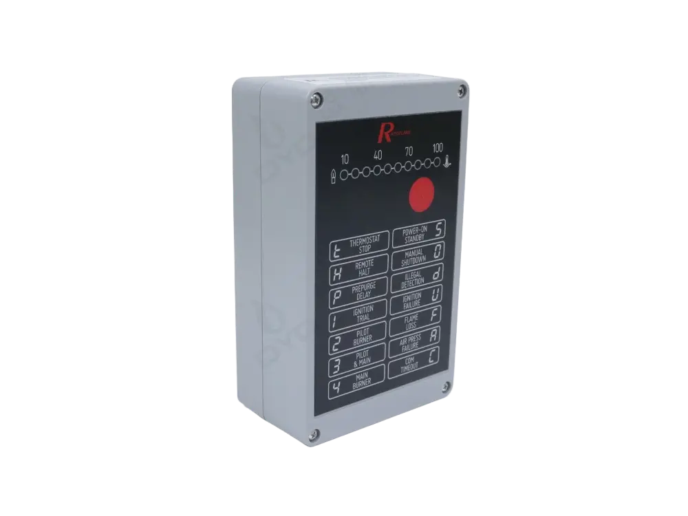
Burner management systems (BMS) that sequence startup, monitoring, and shutdown.
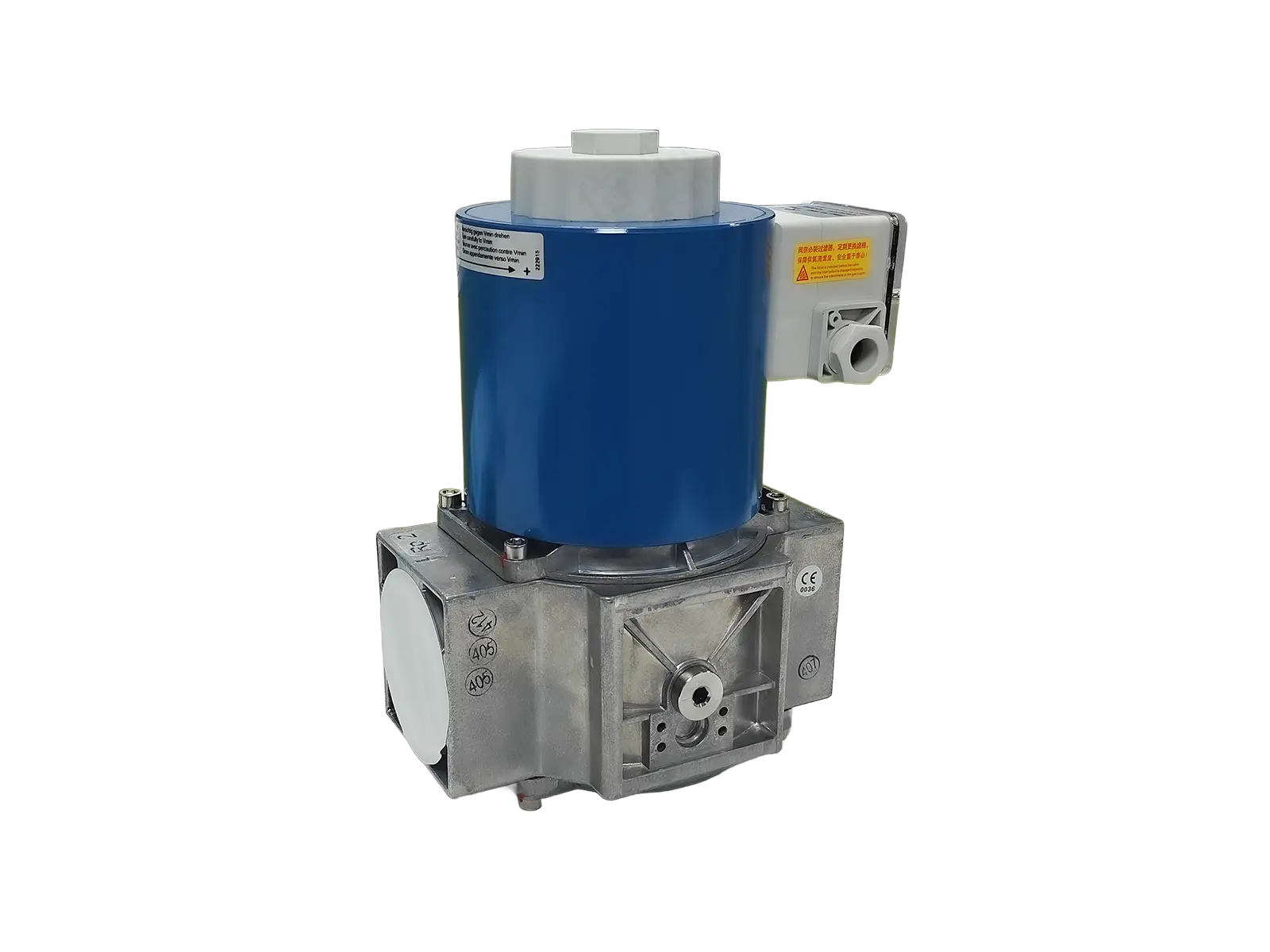
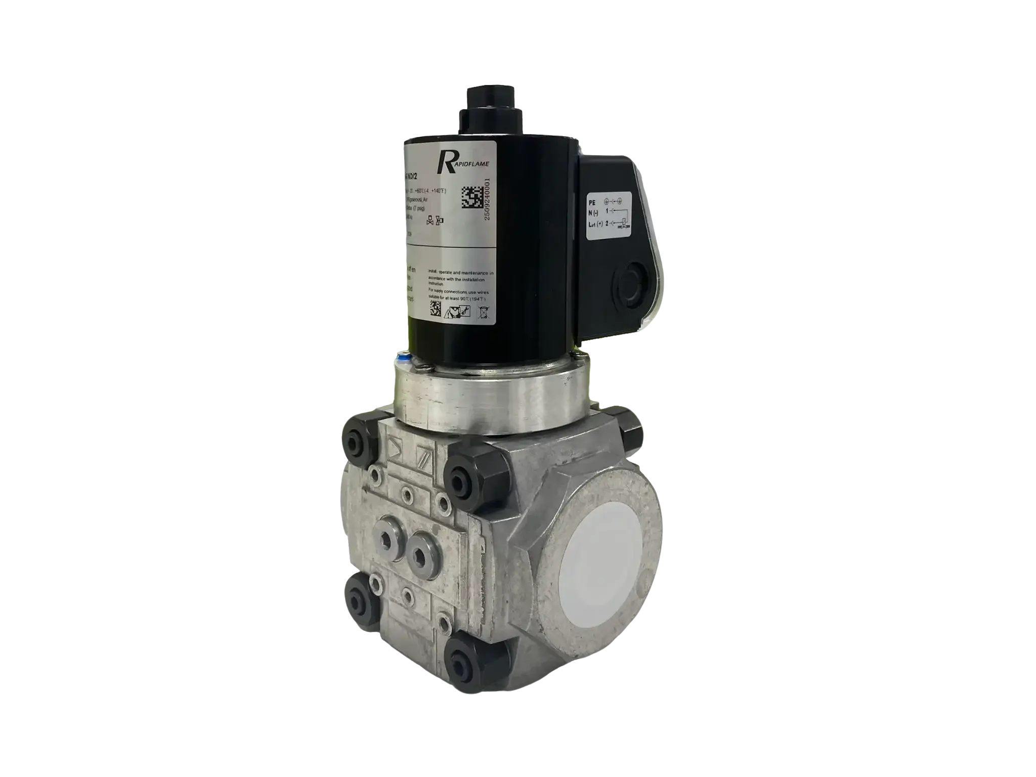
Safety shut-off valves that provide positive fuel isolation.
Pressure switches that verify fuel and air supply conditions.
Airflow monitoring systems that confirm proper ventilation.
Together, these components create a complete safety chain that ensures fuel is supplied only when all conditions are safe.
Typical safety logic:
No Flame → Fuel Shutoff → Alarm → Safe Shutdown
This sequence must occur within the safety time limits defined by applicable codes and standards to prevent hazardous fuel accumulation.
Selection depends on a range of application-specific factors that determine which detection technology is most suitable.
Different fuels create different flame characteristics. Natural gas produces strong UV emissions, while oil and coal flames may generate more IR radiation. The fuel determines the primary signal available for detection.
Consider the flame size, shape, and location relative to the detector mounting position. A small burner with a compact flame may require different detection than a large industrial burner with a long, penetrating flame.
Critical processes may require dual-sensor detection, UV/IR systems, or redundant detection channels to achieve the required safety integrity level. Processes with high value or safety risk typically demand more robust detection.
Consider the furnace environment, including dust levels, temperature, radiation interference, and accessibility for maintenance. Harsh environments may require special housings, purged viewing ports, or cooled detector assemblies.
Modern low-NOx burners often operate with complex combustion strategies that can affect flame characteristics and detection. The flame may be less intense, more diffuse, or have different spectral emissions compared to conventional burners.
Stable flame detection becomes more important because:
Flames may be less intense, particularly with staged combustion or flue gas recirculation.
Mixing zones are more controlled, potentially altering flame shape and signal strength.
Operating ranges are wider, requiring detection that is reliable across the full turndown ratio.
Reliable detection ensures that emission reduction technologies do not compromise safety. A detection system that works well with a conventional flame may need adjustment or replacement when transitioning to low-NOx burner designs.
Flame detectors confirm that fuel is actually burning. If the flame disappears, they shut off fuel to prevent dangerous accumulation of combustible gases that could lead to an explosion upon re-ignition.
The burner control system closes the fuel valves and performs a safety shutdown. The burner will typically require a manual reset before it can be restarted, ensuring that the cause of flame loss is investigated and corrected.
The best choice depends on fuel type, burner design, furnace environment, and application requirements. UV, IR, UV/IR, and ionization detectors are all used in different situations. Selection should be based on the specific characteristics of the flame and the operational requirements of the system.
Yes. Advanced flame detectors can monitor flame signals continuously and identify flame loss or unstable combustion conditions. Many modern detectors use signal processing algorithms to distinguish between stable and unstable flames, enabling early warning of developing problems.
Maintenance frequency depends on operating conditions, but regular inspection and cleaning are necessary for reliable operation. In dirty or high-temperature environments, weekly checks may be required, while cleaner applications may permit longer intervals. Always follow the manufacturer's recommendations and applicable safety standards.
Flame detection is one of the most important safety technologies in industrial combustion systems. It ensures that fuel is supplied only when a reliable flame exists and immediately protects equipment when combustion is interrupted. Without effective flame detection, the risk of fuel accumulation, explosion, and equipment damage is unacceptably high.
A properly designed flame detection system provides:
Safe burner operation, with automatic protection against flame failure.
Reliable ignition confirmation, ensuring the burner only proceeds when combustion is established.
Fast flame failure response, preventing fuel from flowing without combustion.
Reduced explosion risk, protecting personnel and equipment.
Stable combustion performance, supporting consistent process operation.
In modern industrial burners, flame detection is not just a monitoring device — it is a critical part of the complete combustion control and safety system. Its reliability directly affects both the safety and the operational effectiveness of the entire thermal process.
DYDTEC Combustion specializes in industrial burner technology, combustion systems, and customized thermal solutions. The company provides industrial burner solutions for furnaces, drying equipment, thermal processing systems, and energy-efficient heating applications, focusing on reliable ignition systems, advanced flame monitoring, optimized combustion control, low emissions, and safe long-term operation. With deep expertise in flame detection technologies and combustion safety engineering, DYDTEC supports customers in selecting, installing, and maintaining flame monitoring systems that meet the highest standards of safety and performance across a wide range of industrial applications.