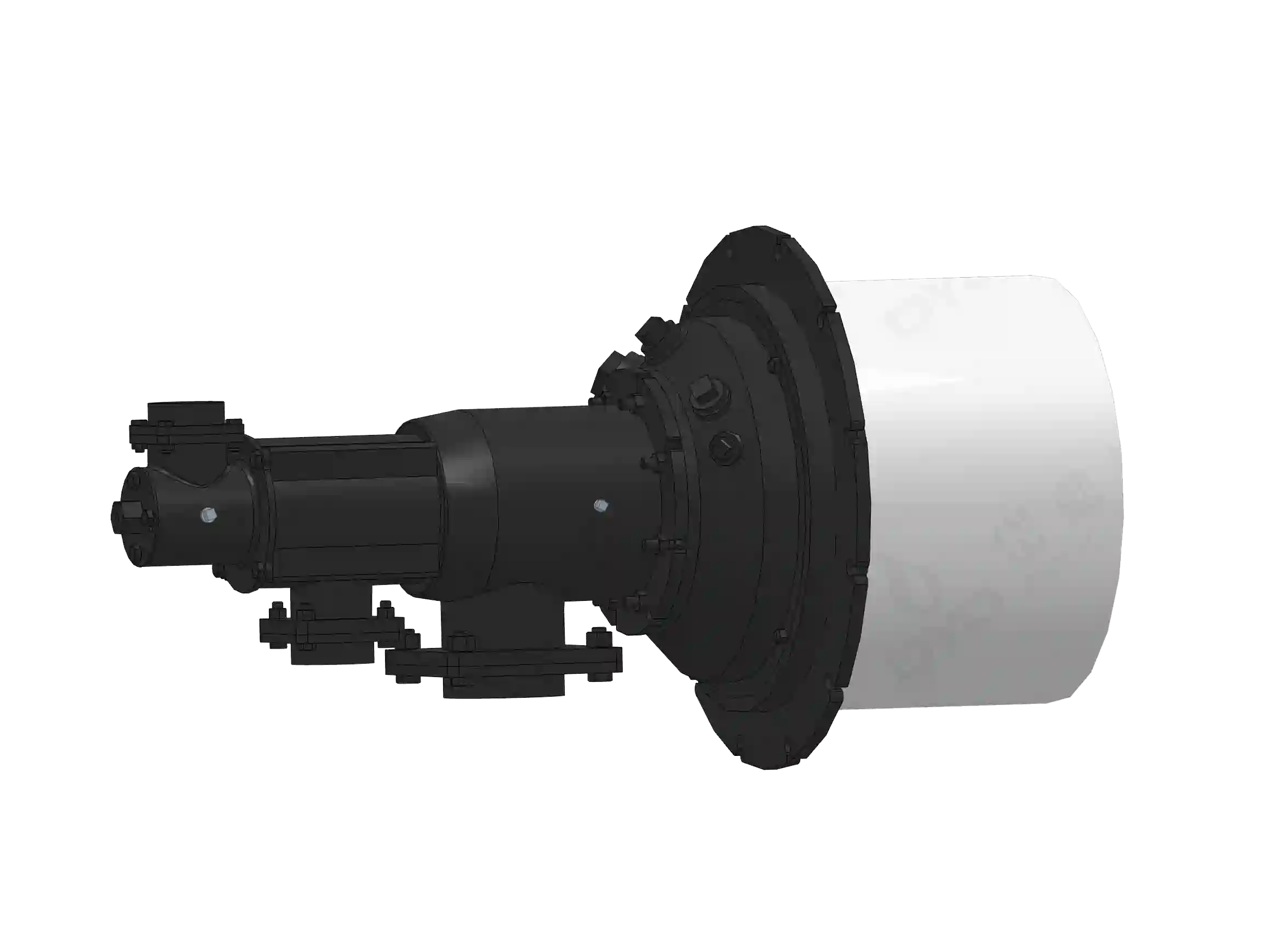
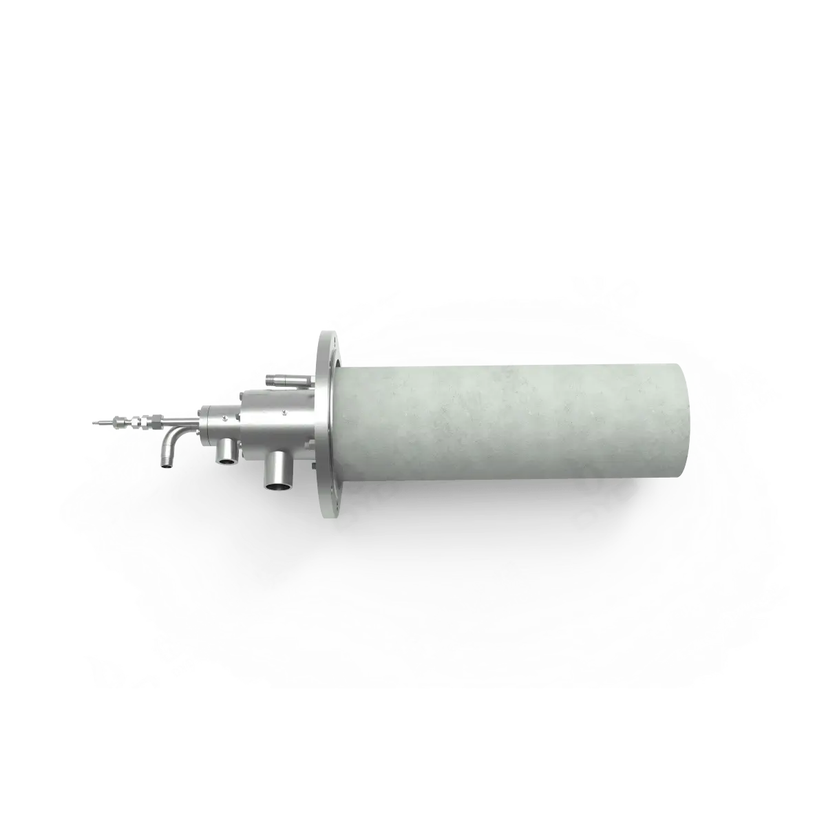
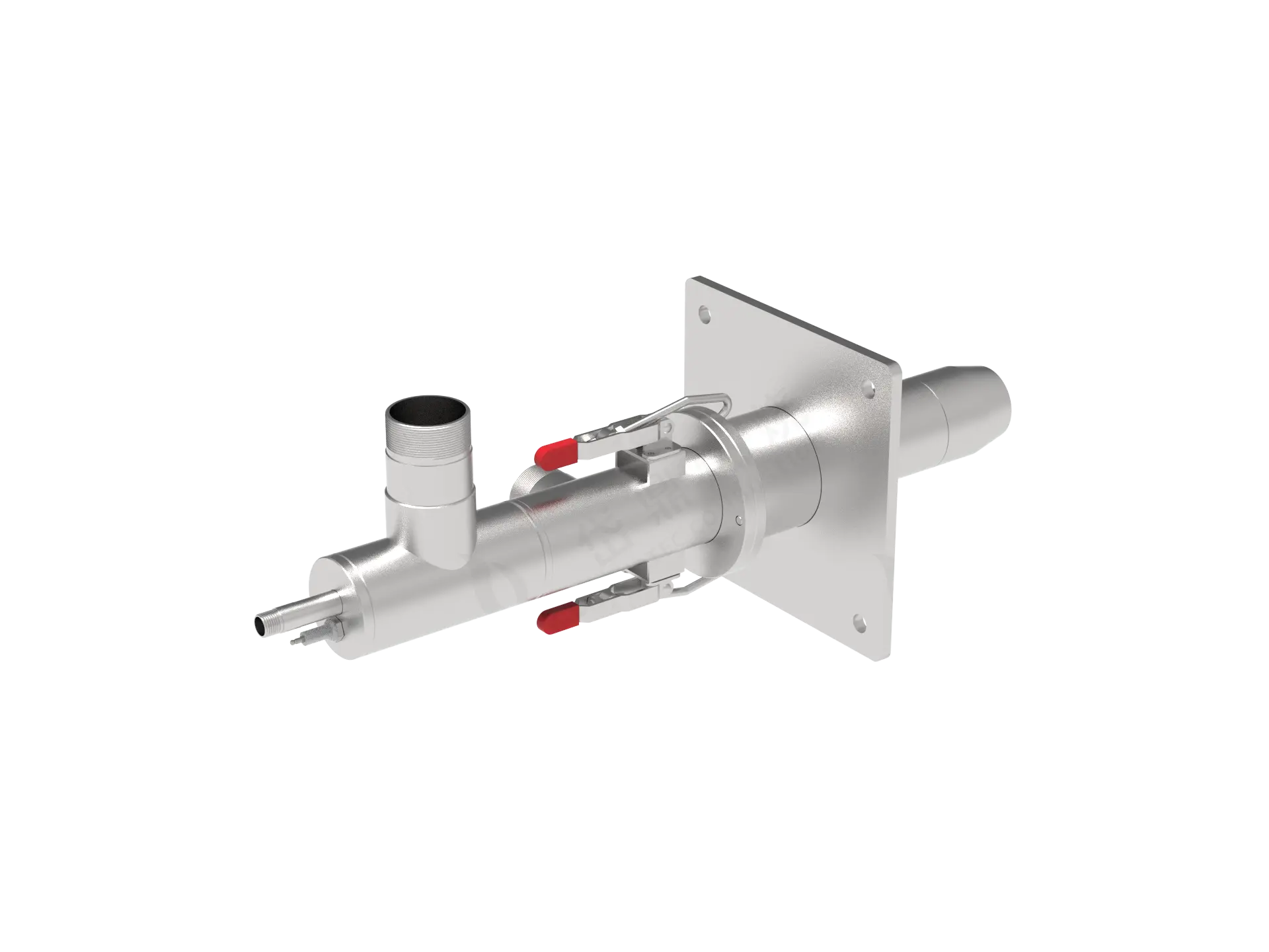
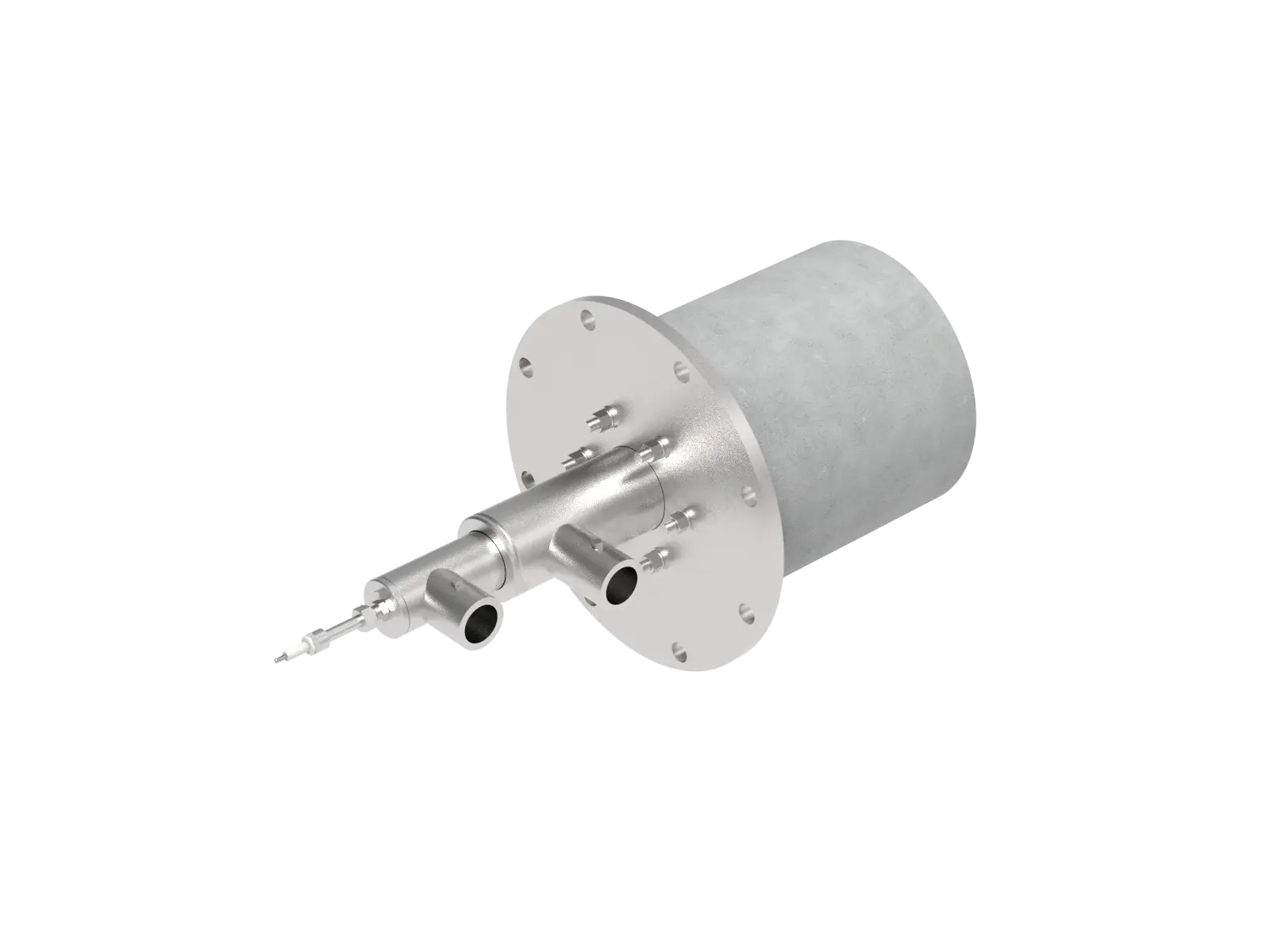
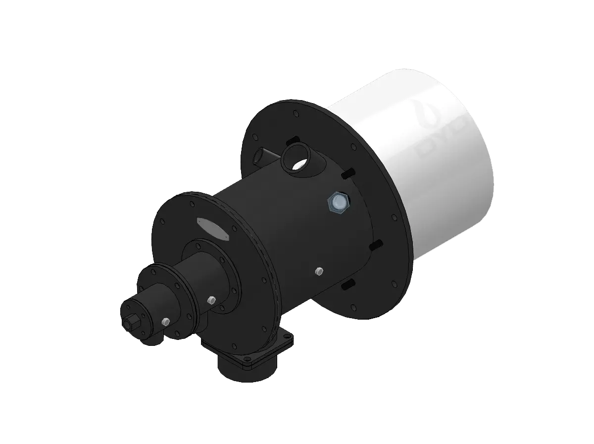
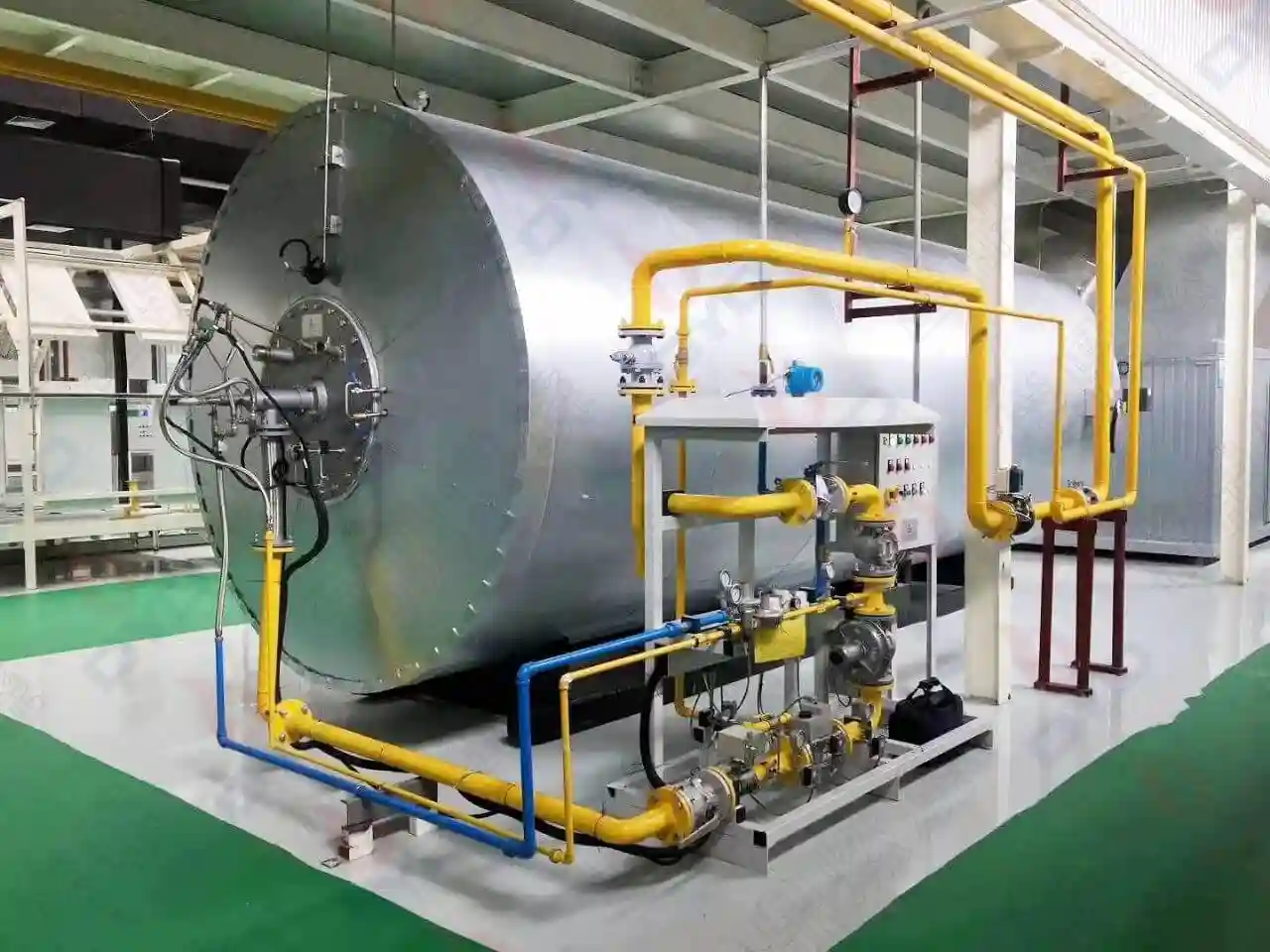
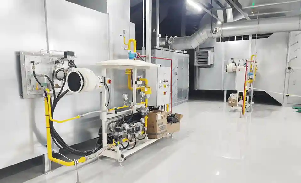
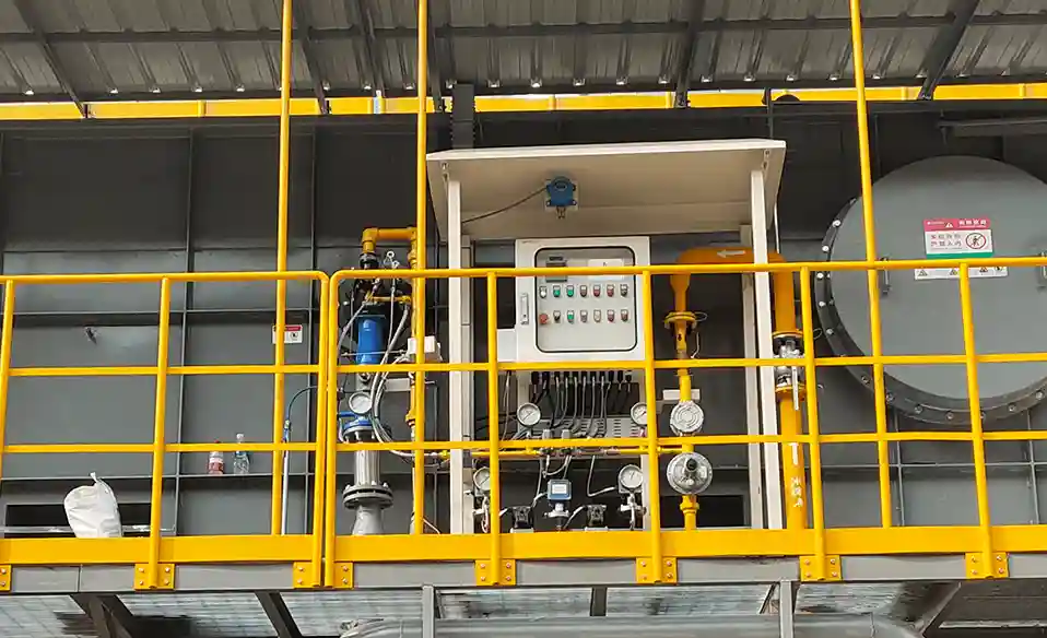
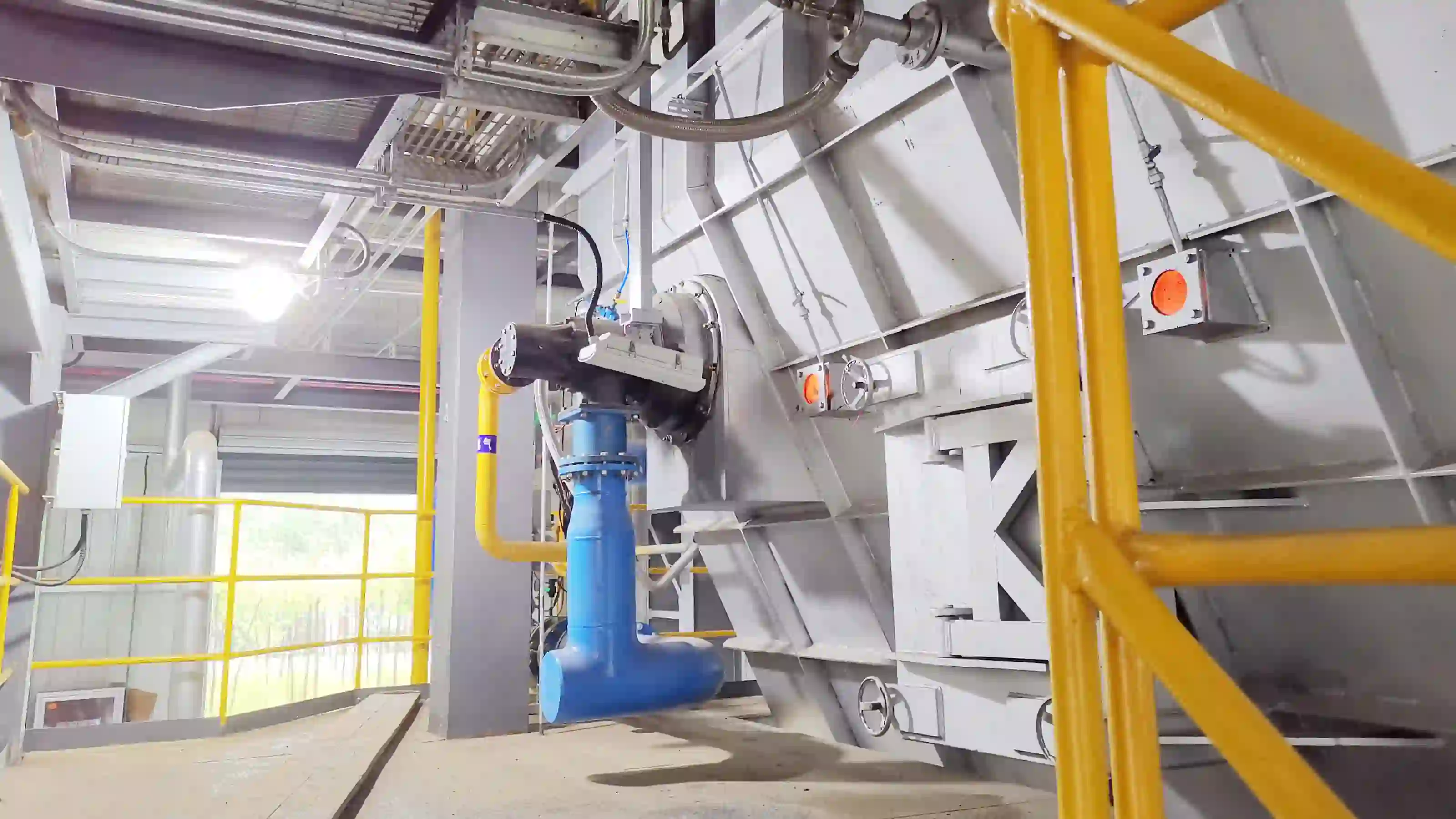
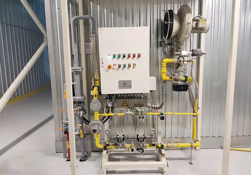
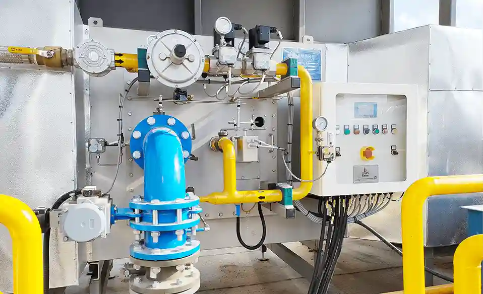
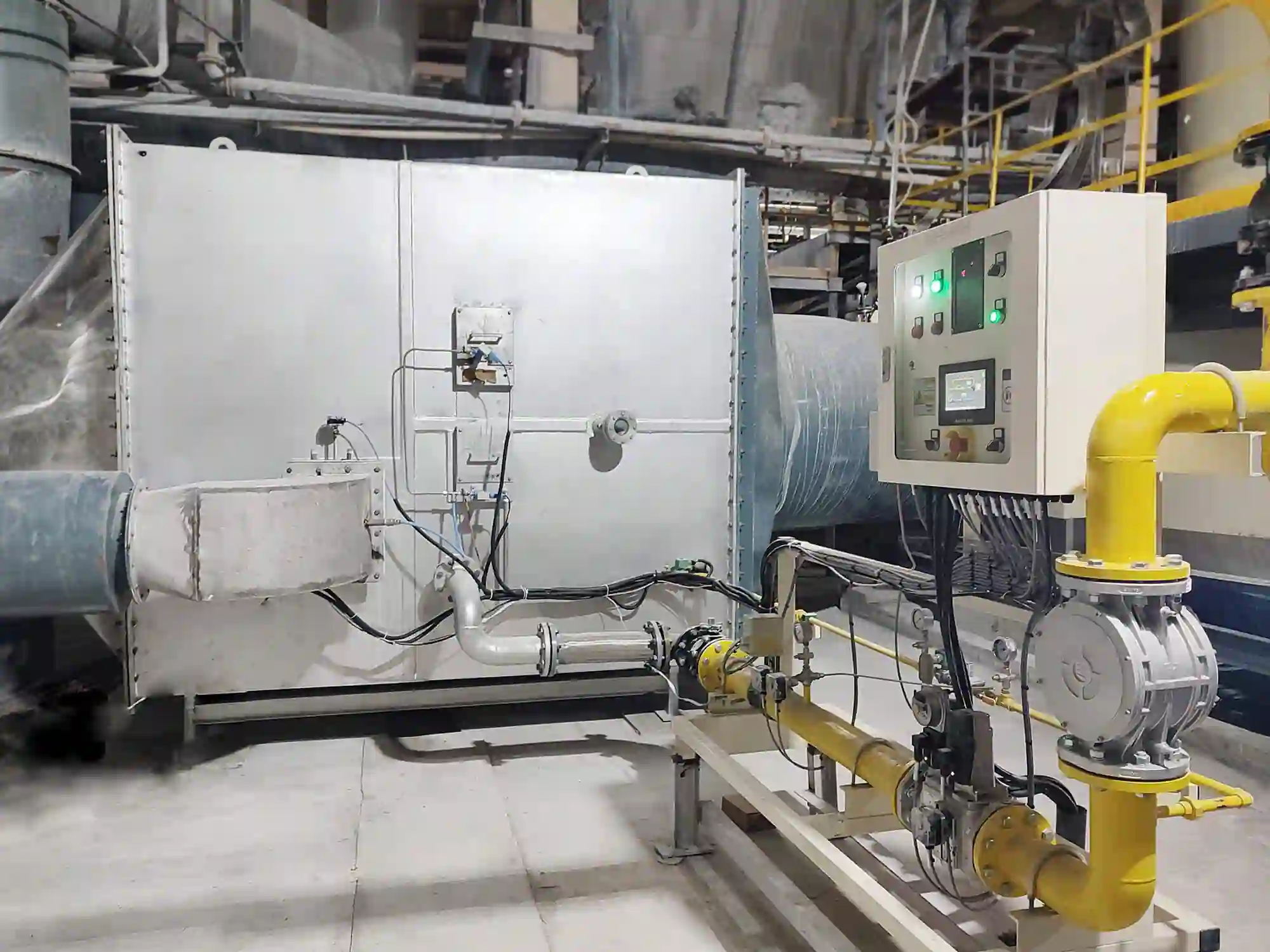
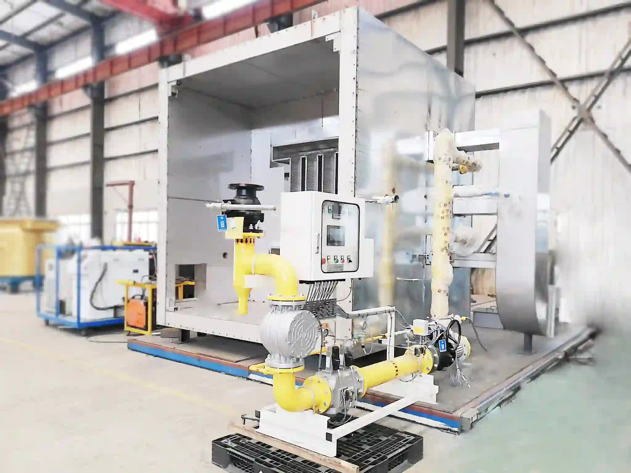
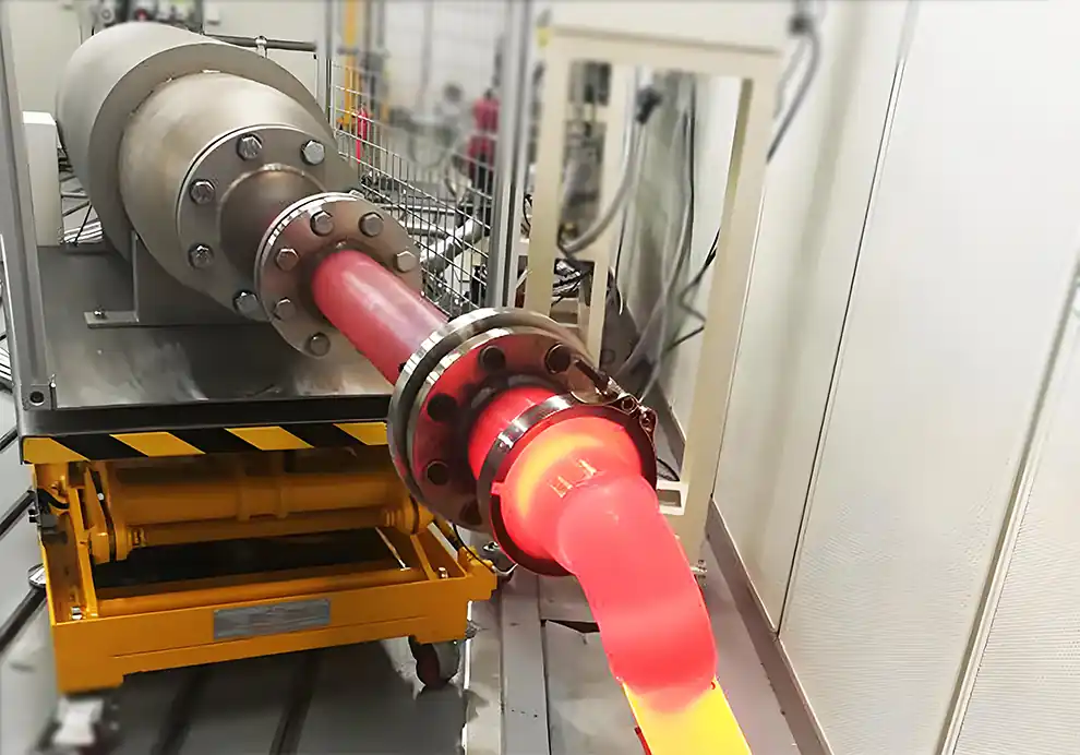
The burner start-up sequence is a carefully controlled series of operations that ensures an industrial burner ignites safely, establishes a stable flame, and reaches normal operating conditions. It is not simply a process of opening a fuel valve and lighting a flame. Rather, it is a precisely orchestrated procedure that coordinates the actions of fans, valves, igniters, sensors, and controllers in a specific temporal order. Every step in the sequence is designed to prevent fuel accumulation, protect equipment, and achieve reliable combustion. A single step performed out of order or at the wrong time can compromise the safety and reliability of the entire system.
In industrial combustion systems, a properly designed start-up sequence directly affects:
Operator safety, by preventing hazardous conditions during the most vulnerable phase of operation.
Burner reliability, ensuring consistent startup on every demand cycle.
Ignition success rate, minimizing failed attempts that waste time and fuel.
Equipment lifespan, reducing thermal and mechanical stress on burner components and furnace linings.
Fuel efficiency, avoiding the waste associated with repeated startup failures.
Emissions performance, by establishing stable combustion conditions from the outset.
Industrial burners used in furnaces, kilns, dryers, thermal oxidizers, and heating systems rely on automatic burner management systems (BMS) to execute this sequence accurately and repeatably, without variation or operator error.
A burner start-up sequence is the programmed order of operations that occurs from the moment a burner receives a start command until it reaches stable firing conditions. It is the automated protocol that governs the transition from a cold, idle state to active combustion, ensuring that all safety conditions are satisfied before fuel is introduced and that combustion is confirmed before the system proceeds to normal operation.
A typical sequence includes:
System safety checks, verifying that all interlocks and permissive conditions are satisfied.
Pre-purge, ventilating the combustion chamber to remove any residual combustibles.
Ignition preparation, activating the ignition source and establishing the conditions for ignition.
Pilot ignition, initiating the pilot flame that will serve as the ignition source for the main burner.
Main fuel release, opening the main fuel valve to admit fuel to the burner head.
Flame detection confirmation, verifying that combustion has been successfully established.
Load adjustment, increasing the firing rate to meet process demand.
Normal combustion operation, with the burner under automatic control.
Each step has a specific purpose and must be completed before the next stage begins. The control system monitors conditions at each step and will not proceed unless all criteria are met.
The basic logic is:
Check Safety → Remove Risk → Ignite → Confirm Flame → Increase Load → Operate
This sequential logic ensures that the burner transitions through progressively higher energy states only when each prior condition has been positively confirmed.
The start-up process is critical because combustion involves storing and releasing large amounts of energy. During startup, the system moves from an inert, fuel-free state to one in which significant thermal energy is being released. This transition must be managed with precision to avoid the accumulation of unburned fuel, which is the primary hazard in combustion systems.
An incorrect start-up sequence may cause:
Explosion risk, from the ignition of accumulated fuel in the furnace or exhaust passages.
Ignition failure, when the fuel-air mixture is not within ignitable limits at the time of spark.
Flame instability, resulting from improper air-fuel ratios during flame establishment.
Excess fuel consumption, from repeated startup attempts or incomplete combustion during the transition.
Equipment damage, from thermal shock, flame impingement, or pressure excursions.
Production interruption, when the burner fails to start and the process must be shut down.
A properly controlled sequence ensures that fuel is introduced only when safe combustion conditions exist—when the chamber has been purged, the ignition source is active, and the air-fuel mixture is within the flammable range.
One of the most important steps in burner start-up is the pre-purge cycle. This step is the primary safeguard against the ignition of accumulated combustible gases that could cause a deflagration or detonation within the furnace or flue system.
Before fuel enters the burner:
The combustion fan starts, typically at full speed or at a designated purge airflow rate.
Fresh air flows through the furnace, displacing any residual gases from previous operation.
Remaining combustible gases are removed through the exhaust system, rendering the chamber inert.
The duration of the pre-purge is determined by the volume of the furnace and the airflow rate, ensuring that the entire chamber volume is exchanged a specified number of times. Standards such as NFPA 86 and EN 746 provide minimum purge time requirements for different types of industrial combustion equipment.
The purpose is to eliminate:
Unburned fuel from previous operation that may have accumulated during a prior shutdown.
Combustible mixtures inside the chamber that could form from the reaction of residual gases.
Unsafe ignition conditions that would exist if fuel were introduced into a chamber containing any combustible gases.
Without adequate pre-purge, accumulated fuel could ignite suddenly upon spark application, causing pressure shock, structural damage, or an explosion that could injure personnel and destroy equipment.
Before ignition, the burner control system verifies that all conditions are suitable for fuel introduction. These checks ensure that the burner is being asked to start only when the necessary support systems are available and operating correctly.
Typical checks include:
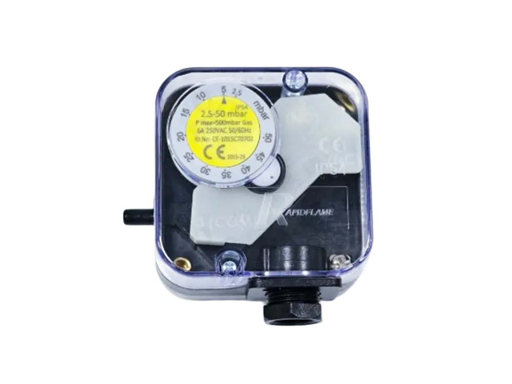
The system confirms that the combustion air system is capable of providing the required airflow for ignition and initial combustion.
Fan operation, verifying that the fan motor is running and delivering air.
Sufficient airflow, confirmed through pressure switches or flow meters.
Correct air pressure, ensuring that the air is at the design pressure for proper mixing.
Insufficient air can cause incomplete combustion, high CO emissions, and flame instability, as well as potentially allowing fuel to accumulate in the furnace.
The system checks the status of the fuel supply system to ensure that fuel can be delivered safely and at the correct conditions.
Fuel pressure, confirming that the pressure is within the acceptable range for the burner design.
Valve status, ensuring that all fuel valves are in the correct position—closed before ignition and leak-tight.
Leakage conditions, with some systems performing a valve proving test to confirm that valves are not passing fuel when closed.
Incorrect fuel conditions may prevent safe ignition by altering the air-fuel ratio or allowing uncontrolled fuel release.
The burner verifies that furnace pressure is within the acceptable range for safe ignition and combustion.
Incorrect pressure may affect flame stability by altering the flow pattern and momentum of the combustion jet.
Ignition reliability can be compromised if the pressure gradient between the burner and furnace is too high or too low.
Exhaust flow may be affected, potentially altering the purge effectiveness.
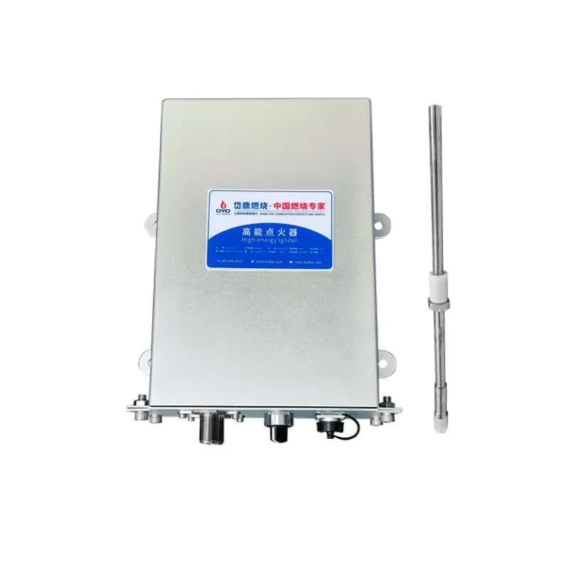
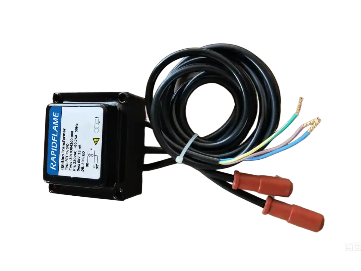
After safety checks and pre-purge, the ignition system activates. This stage establishes a reliable ignition source before the main fuel flow is introduced, ensuring that fuel will ignite immediately upon release.
Common ignition methods include:
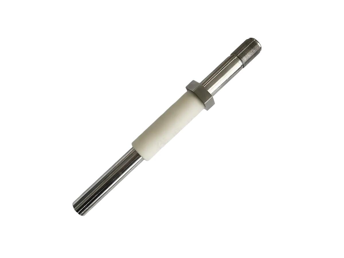
Spark ignition, using a high-voltage discharge to create a localized source of high-temperature energy.
Pilot flame ignition, where a small, continuously burning flame is established first and then used to ignite the main burner.
Hot surface ignition, using an electrically heated element to provide the thermal energy for ignition.
The purpose is to create a controlled ignition source before introducing the main fuel flow, so that the fuel-air mixture encounters an ignition source immediately upon entering the combustion zone.
A reliable ignition sequence prevents:
Delayed ignition, where fuel accumulates before the flame establishes, creating a potential for explosion.
Fuel accumulation, which can occur if ignition fails and fuel continues to flow.
Flame failure, when the ignition source is not sufficient to sustain the flame transition.
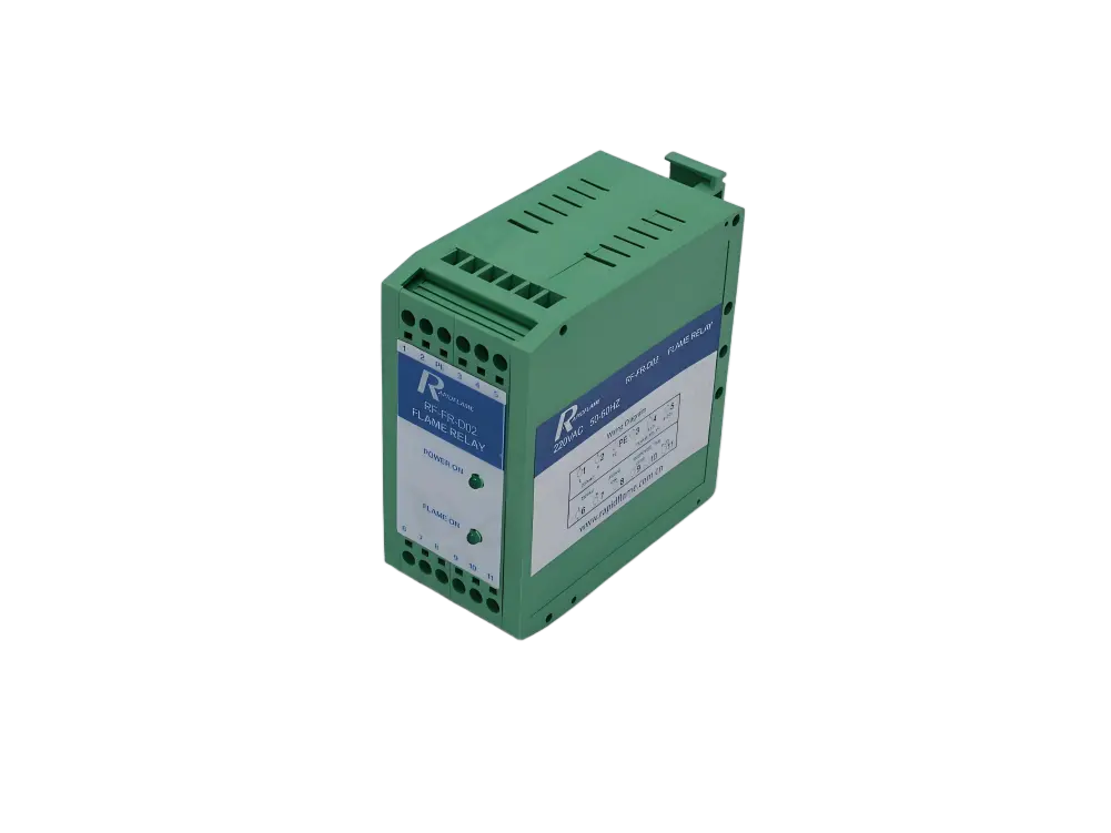
After ignition, the burner must confirm that a stable flame exists before proceeding. This confirmation is a safety-critical step that ensures fuel is not being released without combustion.
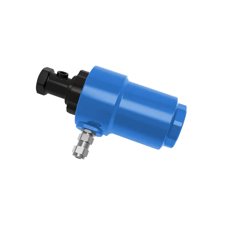
The flame detector monitors the combustion zone for signals that indicate active flame:
UV radiation, characteristic of the high-energy reactions in the flame front.
Infrared radiation, emitted by hot combustion gases and radiating particles.
Ionization signal, created by the conductive ions present in the flame.
If the flame signal is confirmed within the required time window—typically 2 to 5 seconds—the burner continues operation.
If no flame is detected, the fuel valves close immediately. This step prevents continuous fuel release without combustion, which would create an explosive hazard.
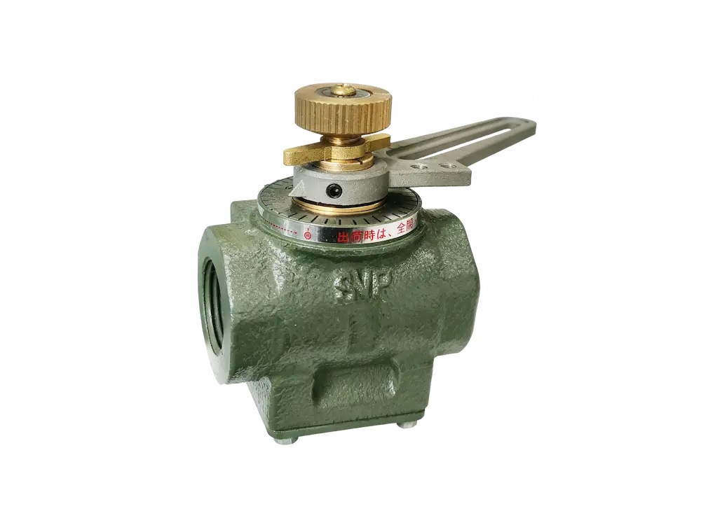
After the pilot flame or ignition source is confirmed, the main fuel valve opens to admit fuel to the main burner. The burner gradually establishes the main flame, with the transition being carefully controlled to avoid abrupt changes in heat release.
A controlled transition prevents:
Sudden heat release, which could create a thermal shock to the furnace lining and structural components.
Thermal shock, resulting from the rapid temperature rise that can crack refractories or warp metal parts.
Flame instability, as the flame transitions from ignition size to full operating size.
This is especially important for large industrial furnaces, ceramic kilns, and high-temperature equipment, where the thermal mass of the structure makes the system sensitive to rapid temperature changes.
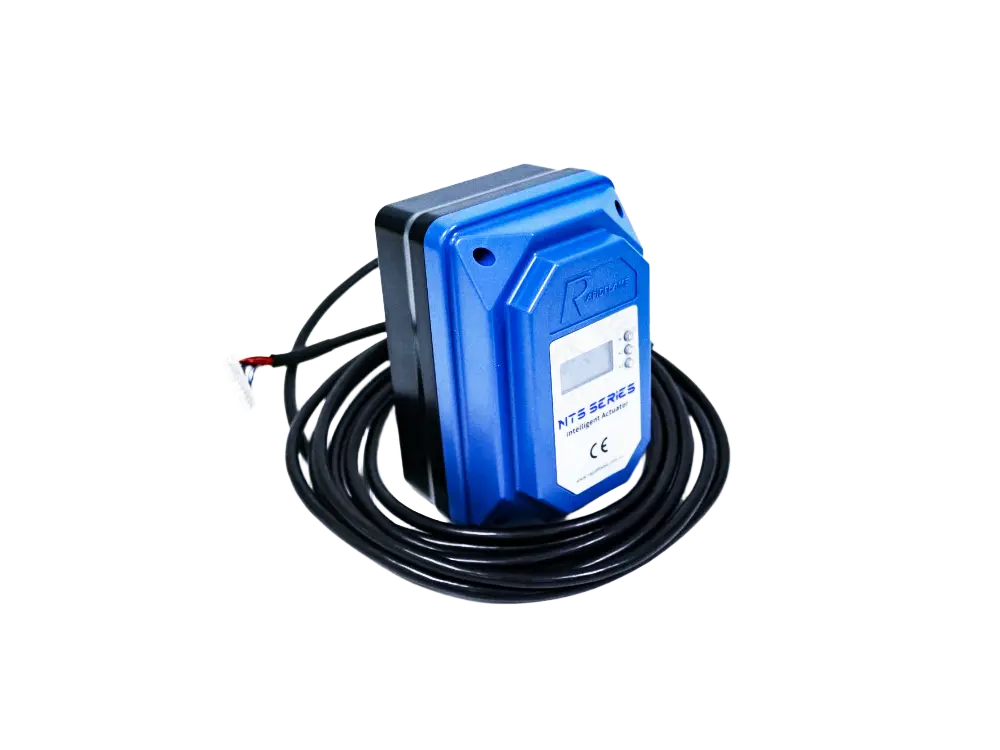
Industrial burners usually do not immediately operate at full capacity. Instead, they increase output gradually in a controlled manner, often following a programmed ramp rate.
The control system adjusts:
Fuel flow, increasing the fuel rate in accordance with the required heat input.
Combustion air, modulating the airflow to maintain the correct air-fuel ratio.
Burner firing rate, raising the output from the ignition level to the process demand level.
Benefits of controlled load increase:
Protects furnace materials from thermal stress and spalling.
Prevents overheating of the load or furnace components.
Maintains stable combustion throughout the transition, avoiding flame instability or excessive emissions.
A standard gas burner sequence follows a logical progression that can be observed in most industrial combustion systems:
The operator or control system requests burner operation, initiating the startup sequence. This may come from a manual pushbutton, a process temperature controller, or an automated scheduling system.
↓
System confirms all safety interlocks are satisfied, including air pressure, fuel pressure, valve position, furnace temperature conditions, and any process-specific permissive interlocks.
↓
Combustion chamber is ventilated with fresh air for a predetermined period, ensuring that any residual combustible gases are removed.
↓
Spark or pilot burner starts, providing the ignition source for combustion.
↓
Flame detector verifies that the pilot flame has been established and is stable.
↓
Main burner receives fuel, with the fuel valve opening only after pilot confirmation.
↓
Control system confirms that stable combustion has been achieved on the main burner.
↓
Burner adjusts output according to process demand, increasing load gradually to the required firing rate.
A burner management system is designed to stop operation when abnormal conditions occur. The system is programmed with safety time limits for each step, and failure to meet those limits results in an automatic shutdown.
Common failure responses include:
Closing fuel valves, stopping the fuel supply immediately.
Stopping ignition attempts, preventing repeated sparking in unsafe conditions.
Activating alarms, notifying operators of the failure condition.
Entering safety lockout mode, requiring a manual reset before the burner can be restarted.
This failsafe design ensures that the burner does not attempt to continue operation when conditions are unsafe.
Possible causes:
Weak ignition spark, resulting from worn electrodes or poor transformer output.
Incorrect air-fuel ratio at the ignition point, with the mixture outside the flammable range.
Fuel pressure problems, either too high or too low for reliable ignition.
Damaged igniter, with physical wear or contamination affecting performance.
Possible causes:
Poor flame stability, from incorrect air-fuel ratio or burner adjustment.
Incorrect burner adjustment, with the flame not properly anchored.
Flame detector problems, including fouling, misalignment, or faulty sensor.
Possible causes:
Safety interlock activation, such as low air pressure or low fuel pressure.
Fuel supply interruption, preventing the fuel from reaching the burner.
Abnormal furnace pressure, creating conditions unsuitable for combustion.
Possible causes:
Excess fuel accumulation before ignition, creating a rich mixture that ignites slowly.
Poor mixing, preventing the formation of an ignitable mixture at the spark location.
Incorrect ignition timing, with the spark occurring before or after the optimal fuel-air condition.
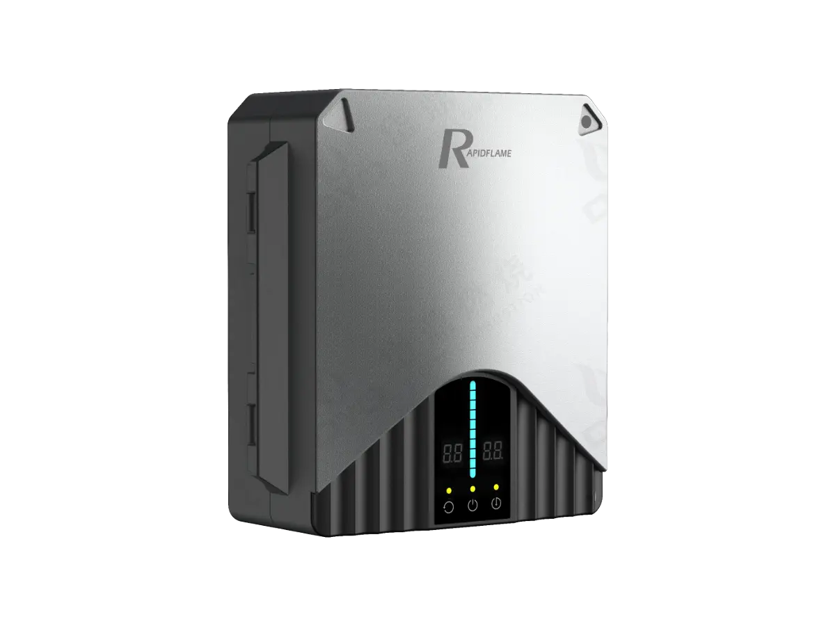
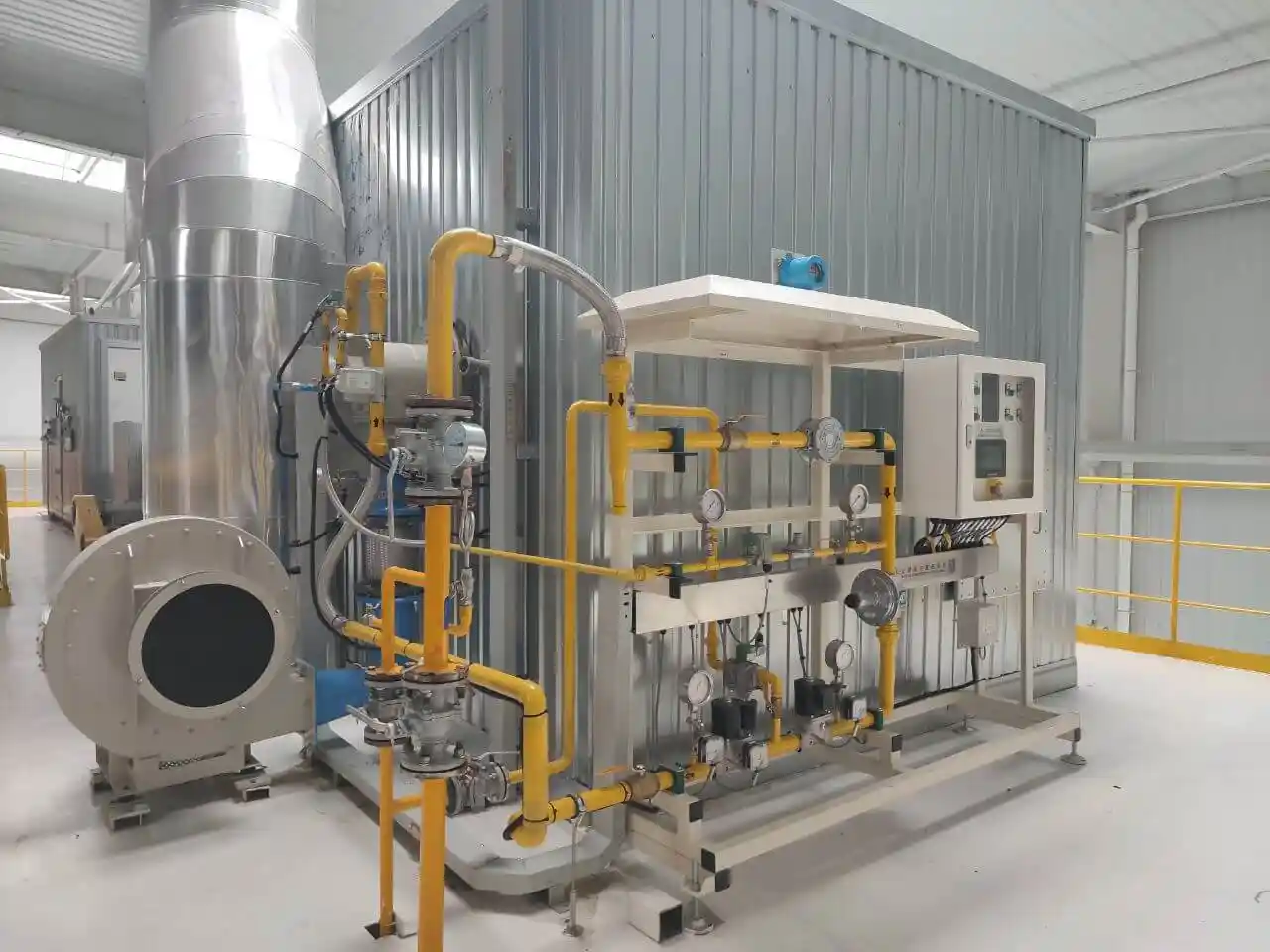
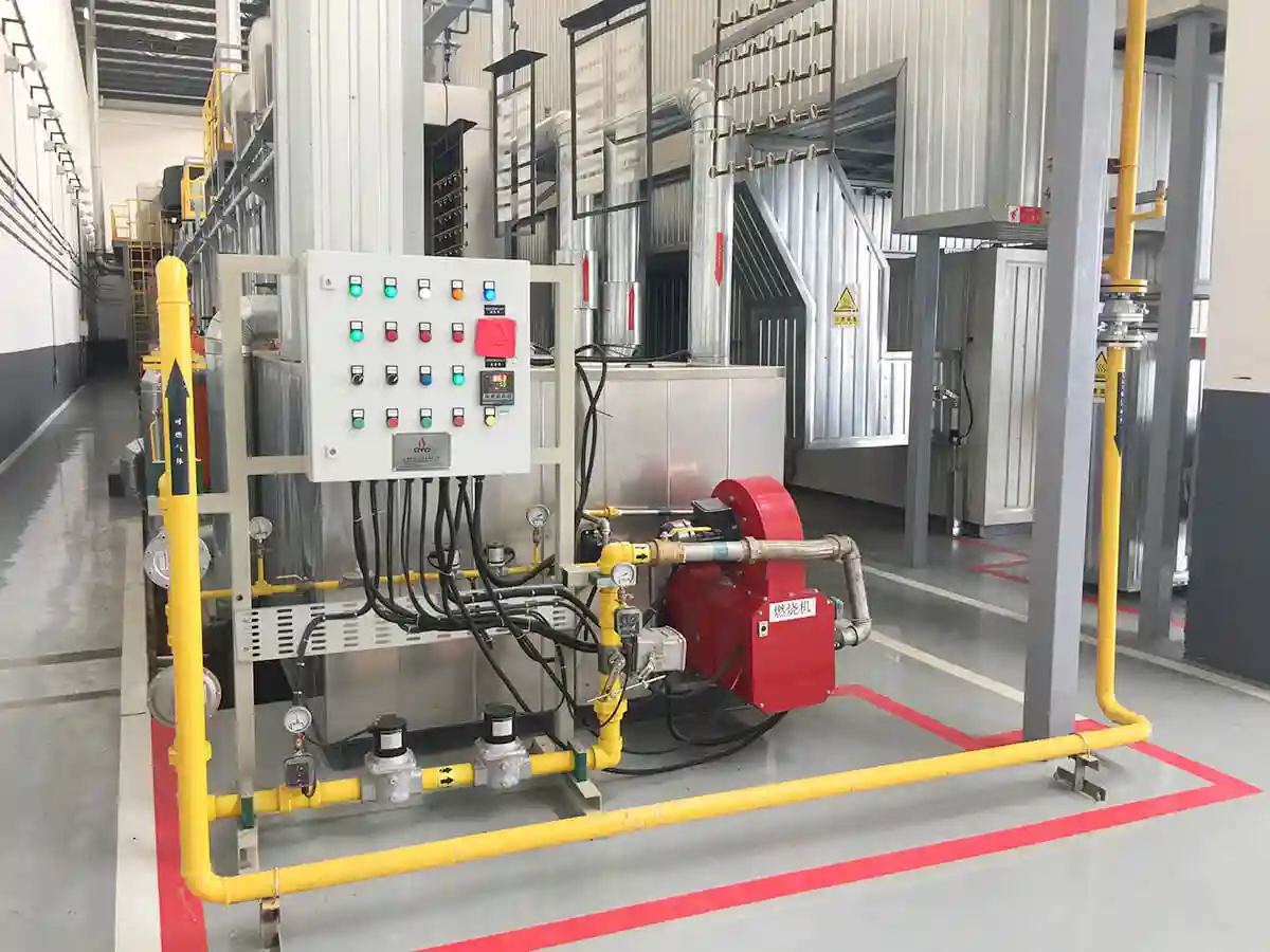
A modern industrial burner start-up sequence relies on multiple safety components working together in a coordinated manner. Each component contributes to the overall safety integrity of the system.
Key components include:
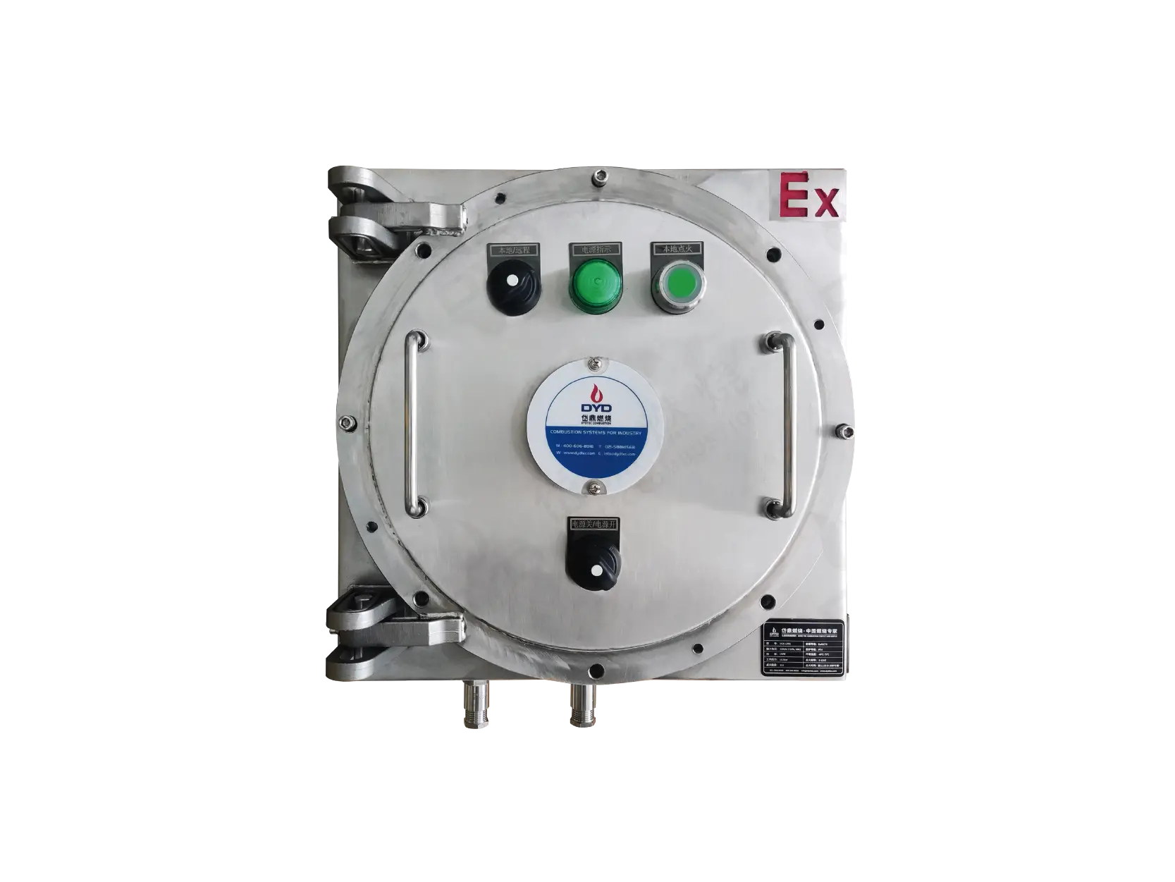
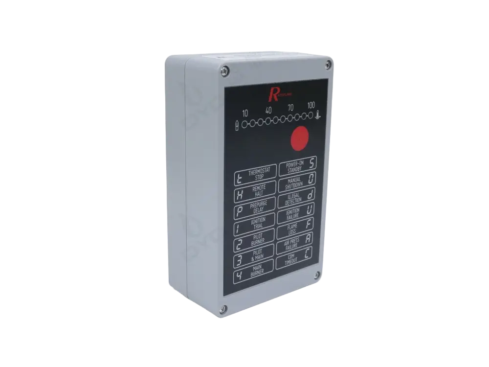
Controls:
Start sequence logic, ensuring steps occur in the correct order.
Safety logic, monitoring interlocks and conditions.
Shutdown procedures, executing emergency and normal shutdowns.
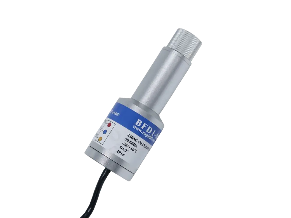
Confirms:
Ignition success, verifying the flame after ignition attempts.
Continuous flame presence, monitoring during normal operation.
Control:
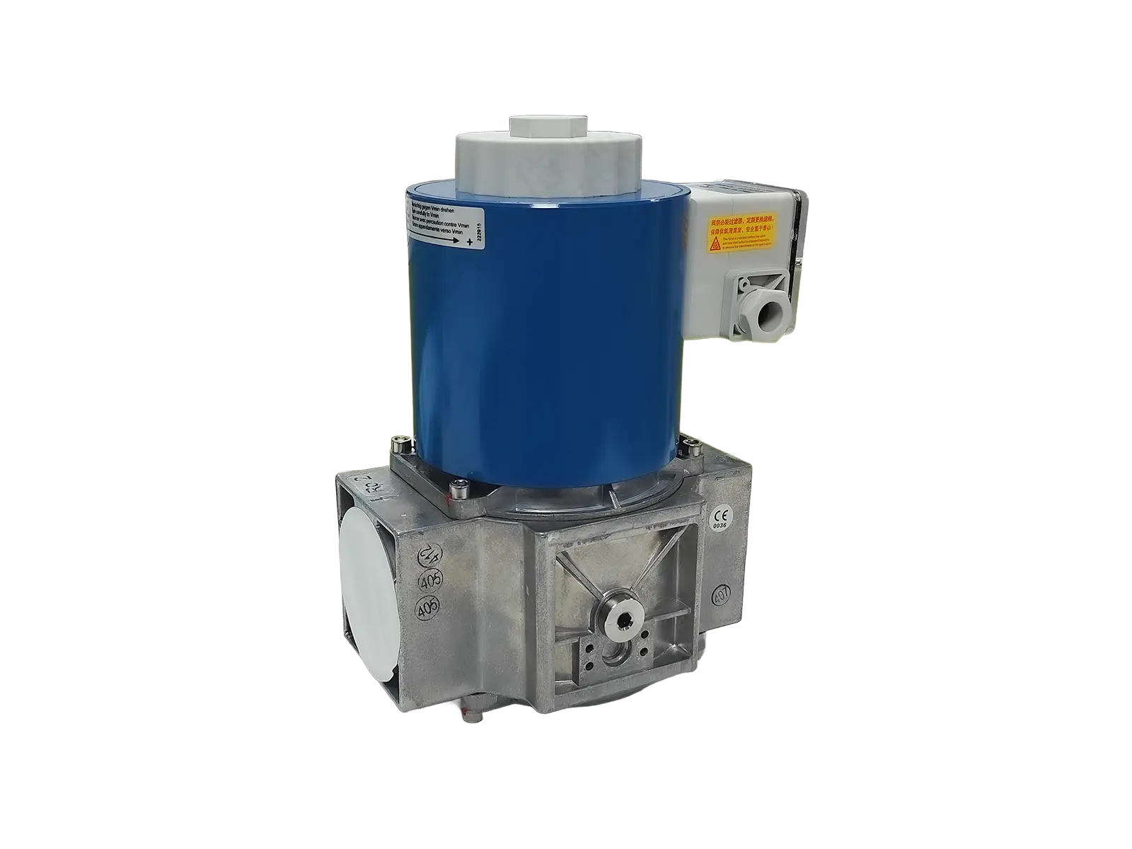
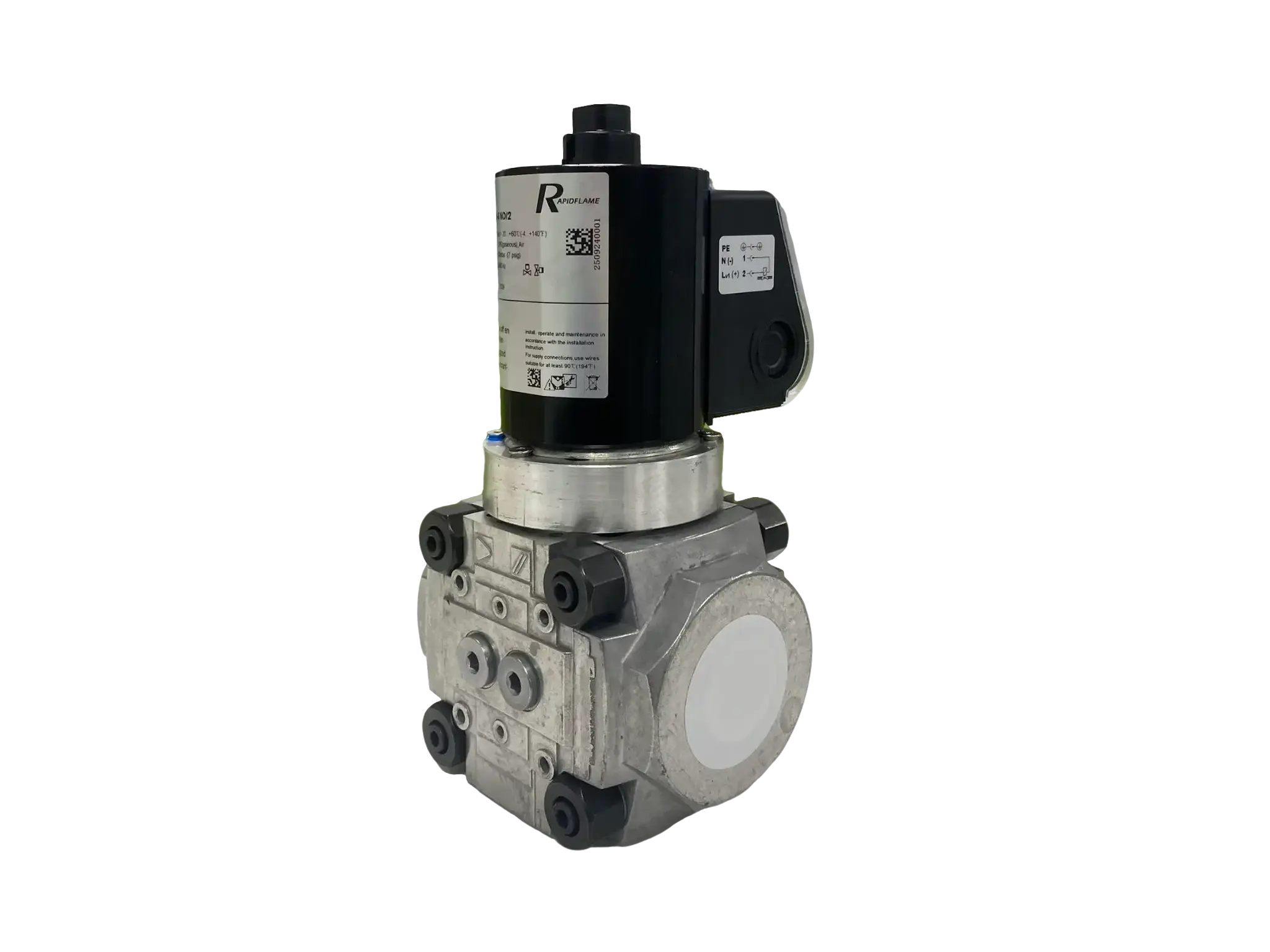
Fuel release, opening and closing at the correct times.
Emergency shutdown, isolating fuel immediately upon safety demand.
Monitor:
Fuel pressure, confirming supply availability.
Air pressure, ensuring combustion air is available.
Furnace pressure, verifying acceptable chamber conditions.
A correct start-up sequence improves efficiency through several mechanisms that reduce waste and optimize the transition to normal operation.
Fewer failed starts mean:
Less fuel waste, as fuel is not discharged during unsuccessful ignition attempts.
Less downtime, keeping the process running and reducing lost production.
Lower maintenance costs, with less stress on ignition components and valves.
Controlled heating reduces:
Thermal stress, which can cause cracking or distortion of metal parts.
Mechanical damage, from sudden pressure changes or thermal expansion.
Premature failure, extending the operating life of the burner.
A proper sequence establishes the correct:
Airflow, ensuring the right velocity and quantity of combustion air.
Fuel flow, matching the fuel rate to the airflow for correct stoichiometry.
Flame position, anchoring the flame at the designed location.
before full operation. This stable foundation allows the burner to operate efficiently throughout its load range.
Important for:
Preventing refractory damage, as controlled heating prevents thermal shock.
Achieving uniform heating, by establishing stable combustion conditions from the start.
Important for:
Preventing overheating, which could damage the product or equipment.
Maintaining stable hot air generation, ensuring consistent drying conditions.
Important for:
Safe temperature rise, avoiding thermal shock to ceramic media.
Reliable VOC destruction, ensuring combustion conditions are stable before waste gas introduction.
Important for:
Controlled temperature increase, matching the thermal sensitivity of the kiln structure.
Protecting materials and structures from thermal stresses.
Because fuel could accumulate without combustion, creating a dangerous explosive mixture. The start-up sequence ensures safe ignition conditions before fuel release, preventing the accumulation of unburned fuel.
Pre-purge and flame confirmation are among the most critical safety steps because they prevent fuel accumulation and ensure reliable combustion. Pre-purge removes hazardous gases, while flame confirmation verifies that combustion has actually occurred.
The burner control system immediately closes fuel valves and stops operation, entering a safety lockout state that requires manual reset before restart.
The time depends on burner size, control system design, and application requirements. Many industrial burners complete the sequence within seconds to several minutes, with larger systems often requiring longer purge times.
The basic safety principles are similar—purge, ignite, confirm—but the exact sequence depends on burner design, fuel type, application, and safety requirements. Different codes and standards may also impose specific requirements for different equipment types.
The burner start-up sequence is the foundation of safe and reliable industrial combustion. It ensures that fuel, air, ignition, and flame monitoring systems work together in the correct order, with each step serving a specific safety or performance purpose. The sequence transforms a cold, inert burner into a stable, efficient heat source while preventing the hazardous conditions that can arise from uncontrolled fuel introduction.
A properly designed start-up sequence provides:
Safe ignition, through purging, checks, and timed fuel release.
Stable flame formation, establishing combustion under controlled conditions.
Reduced fuel waste, with reliable first-time ignition.
Lower emissions, by establishing the correct combustion conditions from the start.
Longer equipment life, through controlled thermal and mechanical loading.
For industrial combustion systems, successful operation begins before the flame appears. The start-up sequence is the critical control process that transforms a cold burner into a stable and efficient heat source, and its design and reliability are fundamental to the safety and productivity of the entire thermal process.
DYDTEC Combustion specializes in industrial burner technology, combustion systems, and customized thermal solutions. The company provides industrial burner solutions for furnaces, drying equipment, thermal processing systems, and energy-efficient heating applications, focusing on reliable burner management, safe ignition sequences, optimized combustion control, low emissions, and long-term operational stability. With deep expertise in burner startup logic, safety system integration, and combustion control engineering, DYDTEC supports customers in designing, commissioning, and maintaining burner systems that meet the highest standards of safety and performance across a wide range of industrial applications.