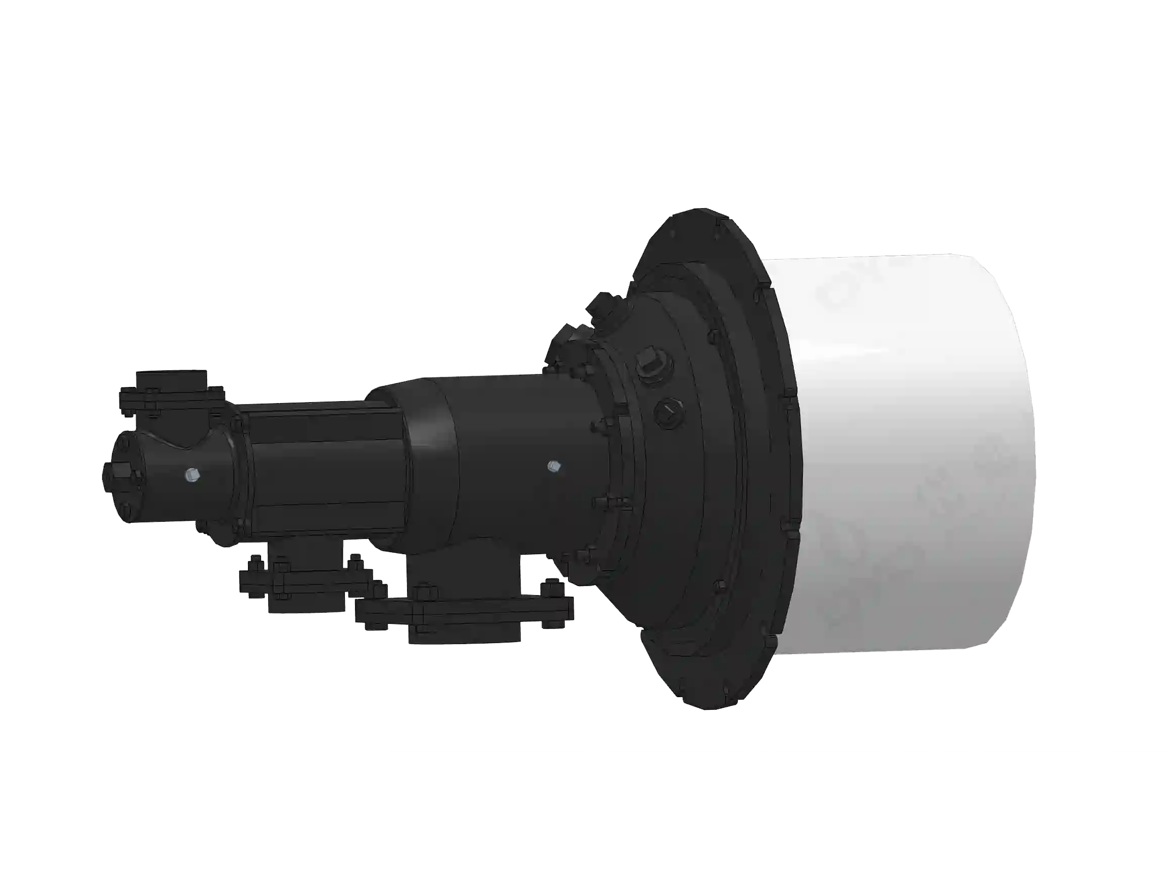
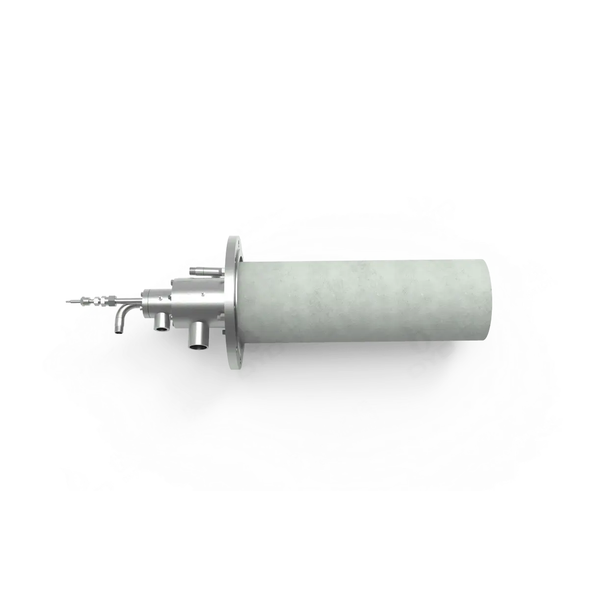
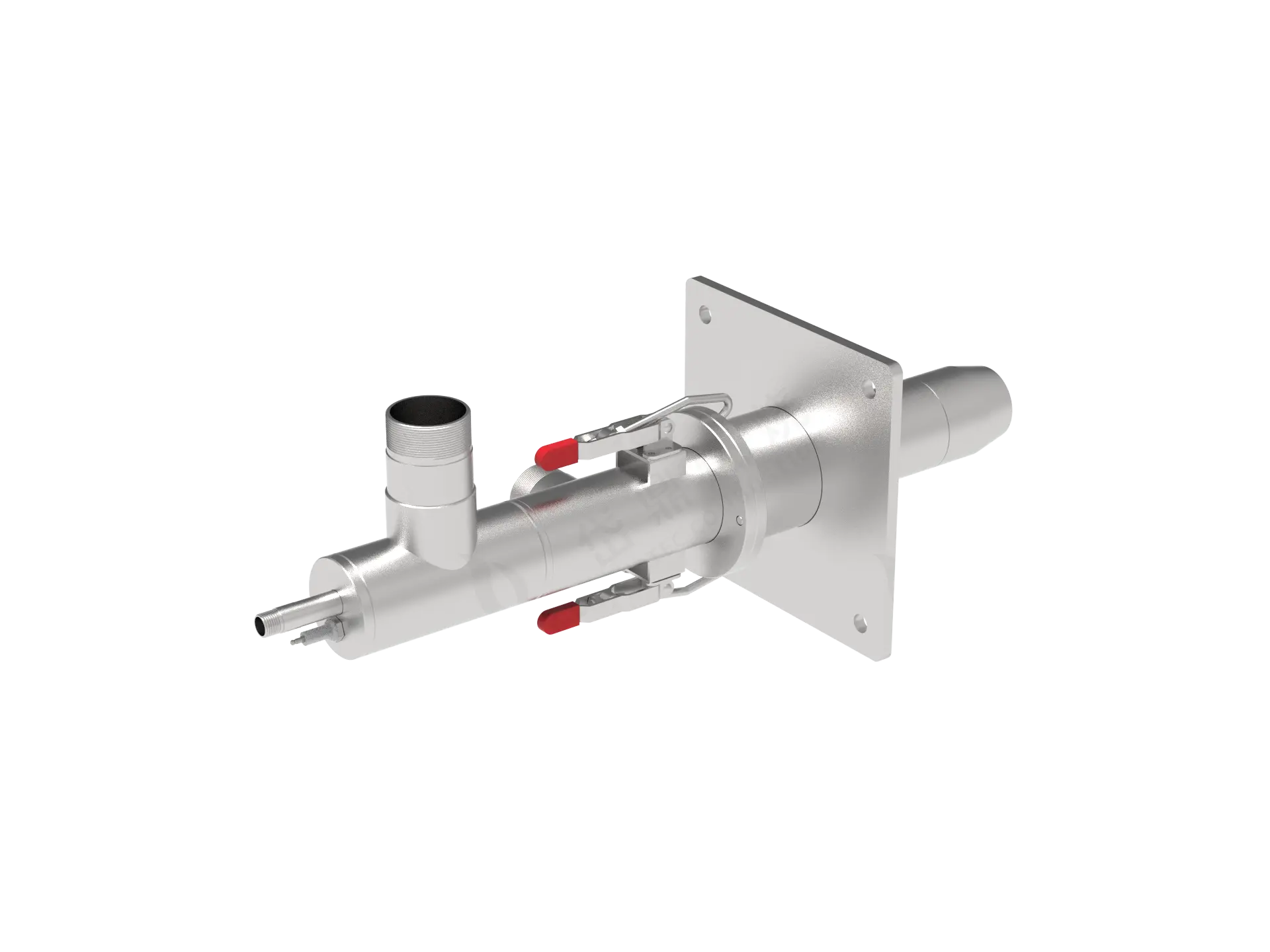
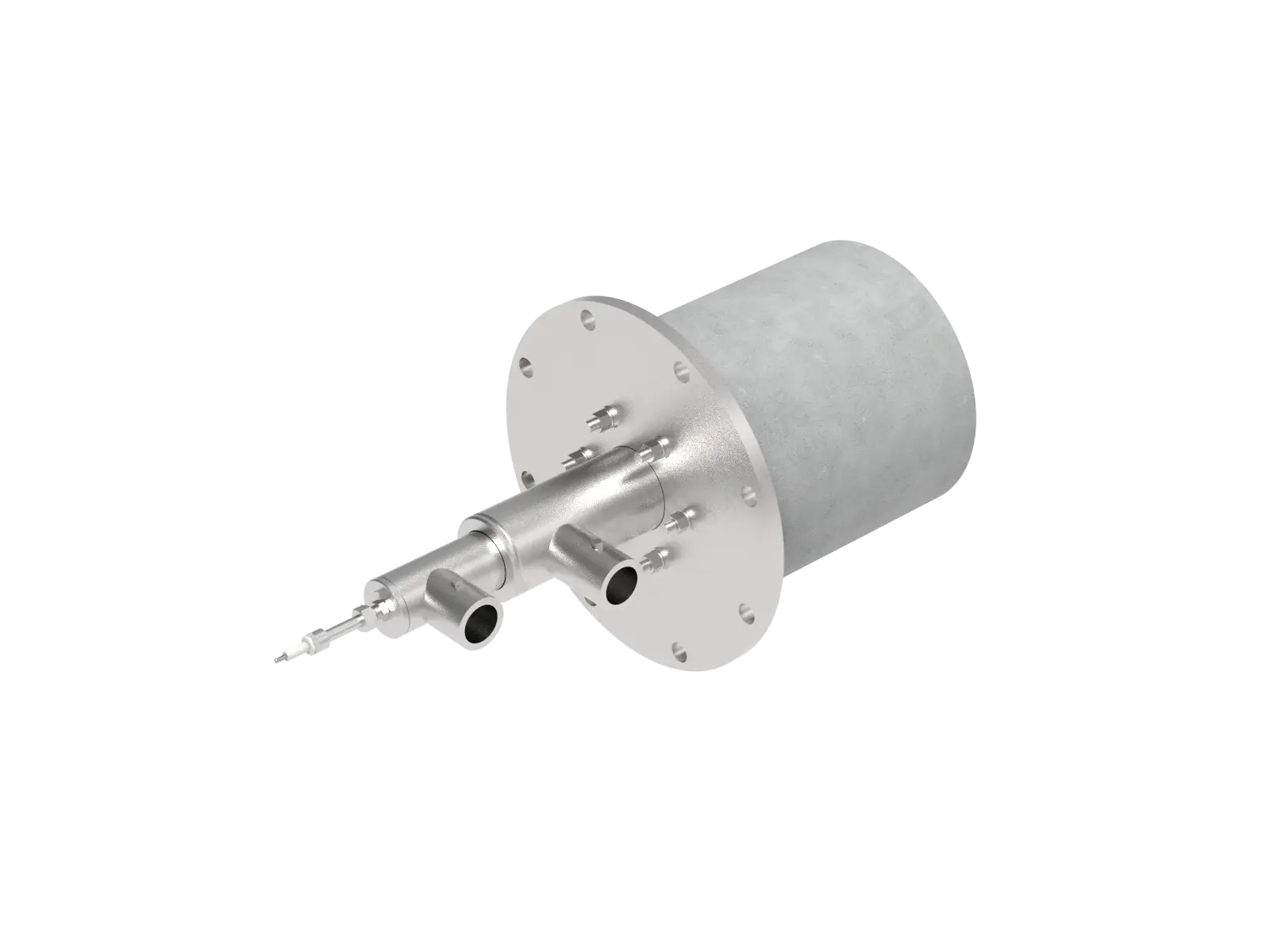
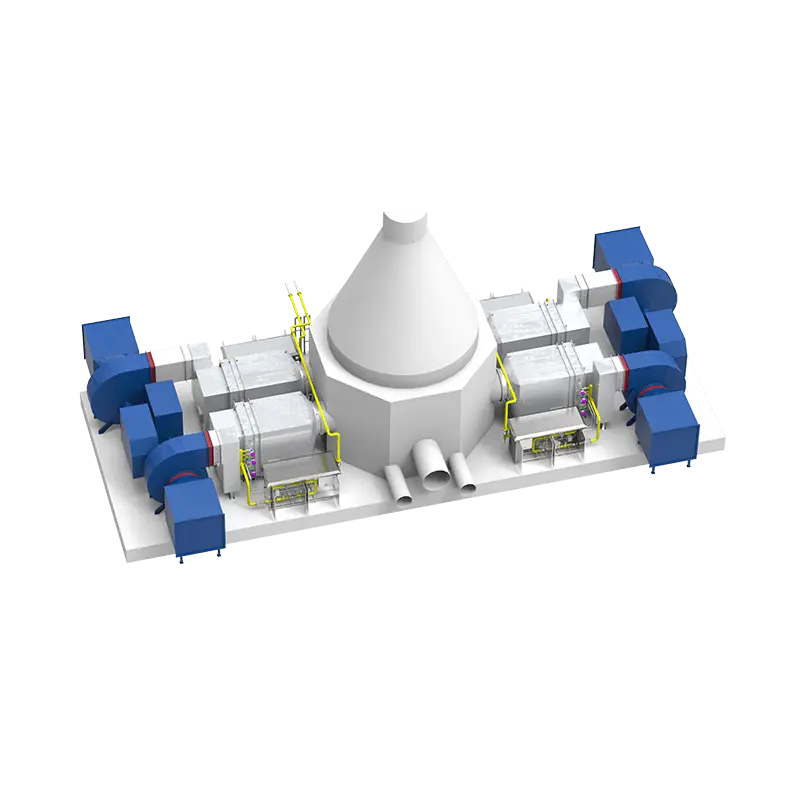
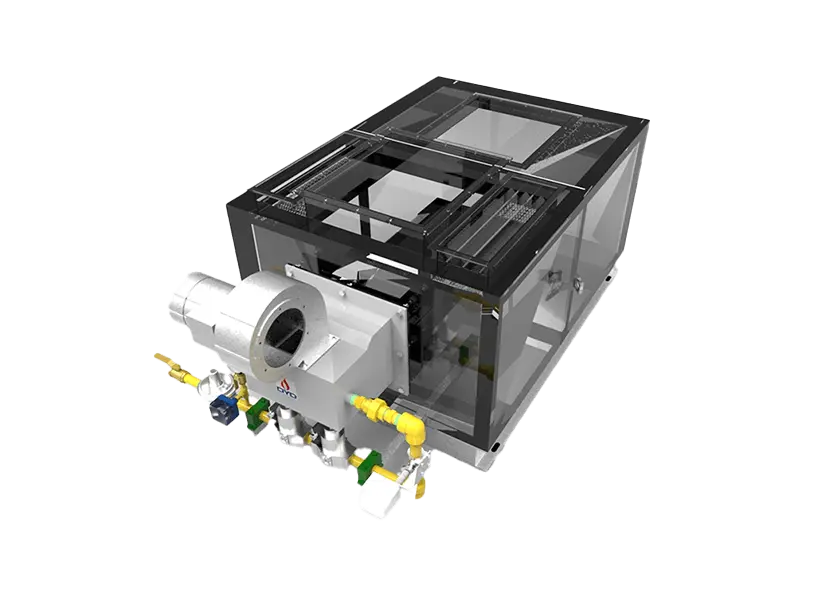
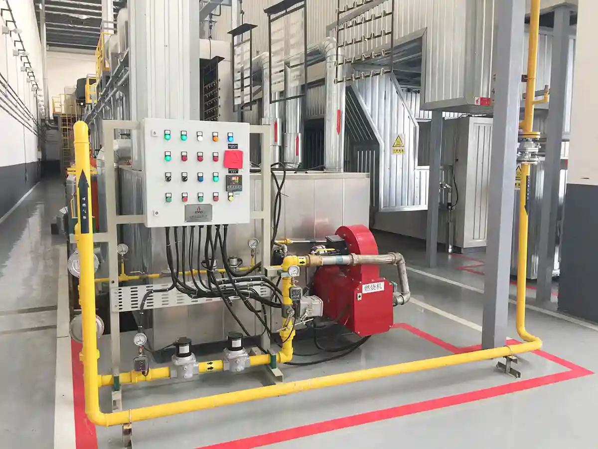
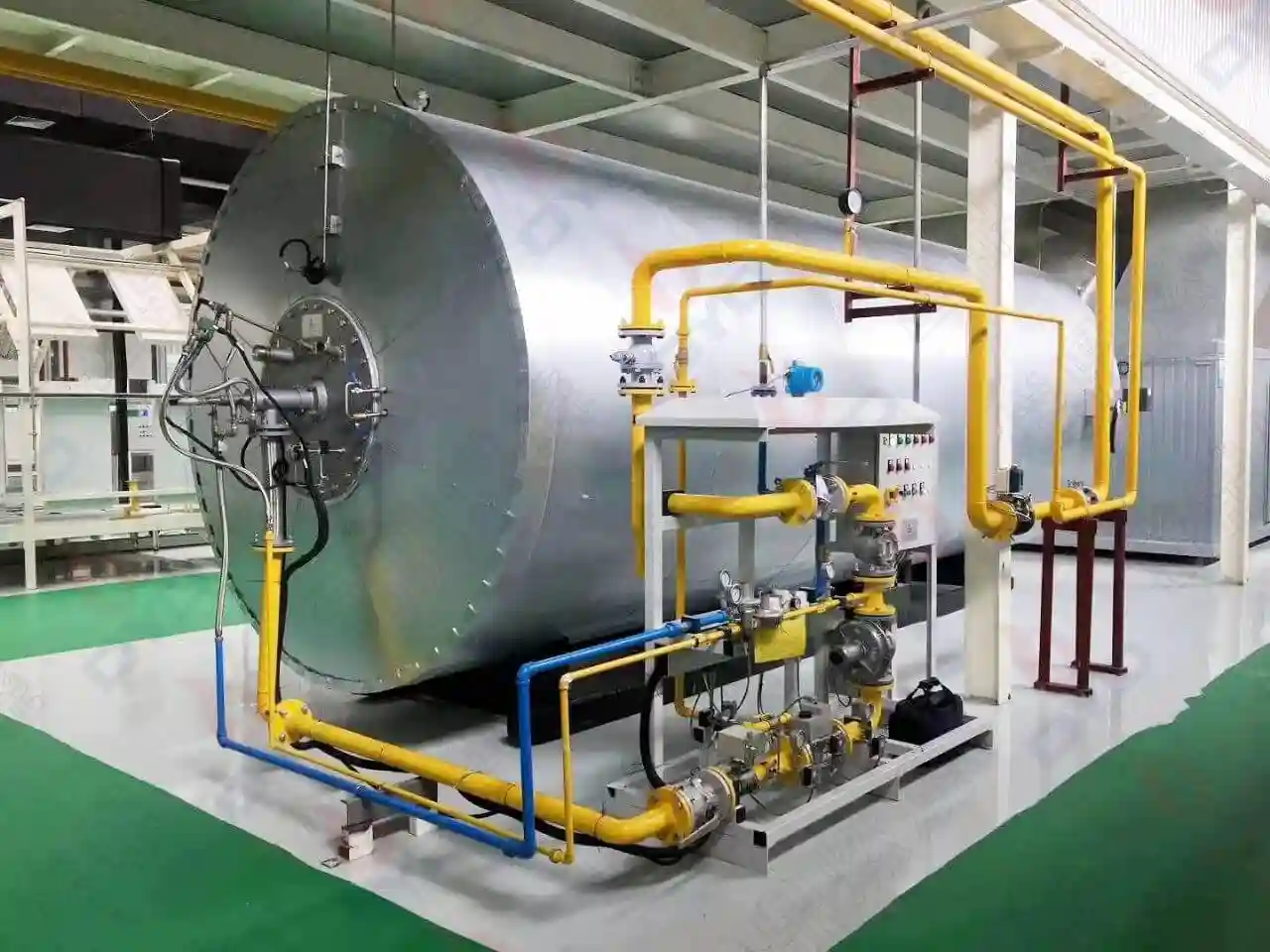
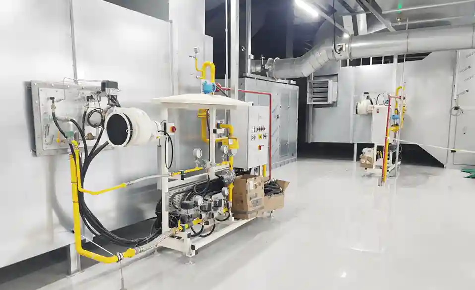
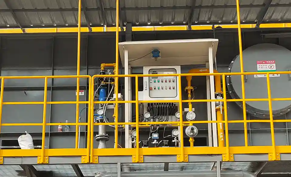
Where a burner is installed inside an industrial furnace can be just as important as which burner is selected.
A burner with the correct thermal capacity can still produce poor furnace performance if it is installed in the wrong position. Burner location affects flame trajectory, heat distribution, temperature uniformity, furnace gas circulation, flame stability, refractory loading, and ultimately the quality and efficiency of the heating process.
The correct burner location is therefore not simply the most convenient position on the furnace wall.
It should be determined by the relationship between:
Burner location → Flame trajectory → Heat release → Furnace gas flow → Heat transfer → Process result
For this reason, burner installation should be considered during furnace design rather than treated as a final mechanical installation step.
There is no universal burner location that works for every furnace.
The correct installation position depends on several factors:
Furnace dimensions
Furnace geometry
Burner capacity
Flame length
Flame shape
Flame momentum
Fuel type
Combustion-air conditions
Workpiece location
Heating-zone requirements
Exhaust location
Burner quantity
Furnace pressure
Required temperature uniformity
Process heating requirements
The basic principle is simple:
A burner should be installed where its flame and combustion gases can create the required thermal field without causing unwanted flame impingement, excessive local heating, or poor gas circulation.
This means burner location must be evaluated together with burner performance.
A burner designed for a long, high-momentum flame may require a very different installation position from a compact burner designed for short flames.
In many industrial furnaces, burners are installed through the furnace wall because this provides convenient access to fuel, combustion air, ignition components, and maintenance points.
However, installing a burner through the wall does not mean that every position on the wall is equally suitable.
The position should be selected based on:
Flame direction
Flame length
Furnace dimensions
Workpiece location
Burner spacing
Exhaust location
Heating-zone requirements
The burner opening should allow the flame to develop properly inside the furnace.
If the burner is positioned too close to an obstacle, the flame may interact with the wall, workpiece, refractory, or another burner before completing its intended combustion path.
Therefore, wall installation is a mechanical arrangement; the actual burner position is a thermal-design decision.
One of the most important considerations is the distance between the burner and the workpiece.
The burner should not automatically be positioned as close as possible to the material.
A short distance can increase heat intensity, but it can also increase the risk of:
Direct flame impingement
Local overheating
Material oxidation
Surface damage
Uneven temperature distribution
Thermal stress
On the other hand, placing the burner too far away may reduce the effectiveness of heat transfer or leave some areas insufficiently heated.
The correct distance depends on the flame characteristics and the process.
For many industrial heating applications, the objective is not to make the flame touch the workpiece.
The objective is to create a controlled high-temperature environment around the workpiece.
Therefore, the correct question is:
Where should the burner be located to produce the required workpiece temperature—not simply where can the flame reach the workpiece?
Usually, not necessarily.
Direct flame impingement is appropriate for some specialized applications, but it is not the default solution for conventional furnace heating.
In a typical heating furnace, the workpiece may be heated through a combination of:
Flame radiation
Hot-gas convection
Furnace-wall radiation
Heat recirculation
Pointing the flame directly at the product may create a high local heat flux while leaving other areas comparatively cold.
This can result in uneven heating.
For specialized flame-treatment processes, however, direct and controlled flame exposure may be the actual objective.
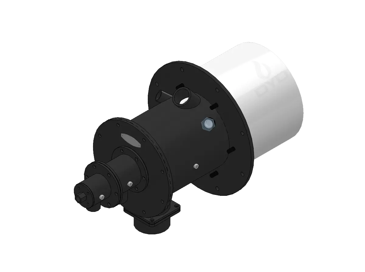
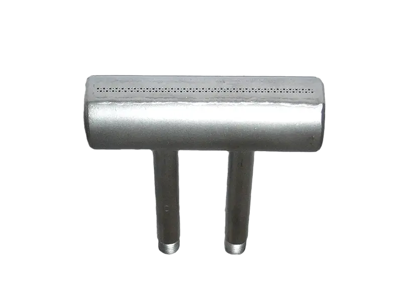
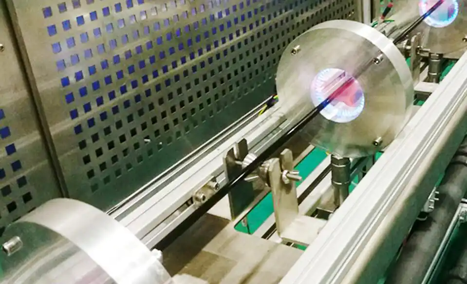
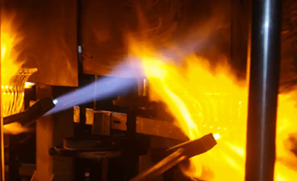
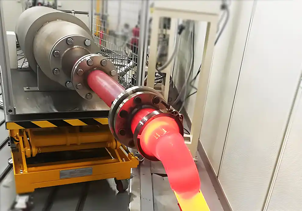
DYDTEC Combustion's flame-treatment burner range covers applications such as surface activation, deburring, stress relief, welding preheating, mold preheating, hot forming, and glass flame polishing. The burners can be customized in different shapes and power levels according to application requirements.
This illustrates an important principle:
The correct burner position depends on the process objective.
Long furnaces often require careful burner positioning because the available heating volume extends over a considerable distance.
A common design approach is to distribute burners along the length of the furnace rather than concentrating all heat in one location.
The objective is to create multiple heating zones.
Depending on the process, burners may be arranged to provide:
Preheating
Main heating
High-temperature heating
Soaking
Controlled cooling or temperature transition
The burner arrangement should match the thermal profile required by the process.
For example, a furnace may require lower heat input in the entrance zone and higher heat input in the central heating zone.
Installing identical burners at identical positions does not automatically produce a uniform thermal profile.
The burner capacity, burner spacing, installation angle, flame length, and control strategy should all be considered together.
A wide furnace creates a different problem.
If the burner arrangement is concentrated along one side, the opposite side may receive insufficient heat.
This can produce lateral temperature differences.
For wide furnace chambers, designers may distribute burners across multiple positions so that the combustion gases can cover the required furnace volume.
Possible arrangements include:
Opposing burners
Staggered burners
Multiple burner rows
Symmetrical burner layouts
Multi-zone burner arrangements
The actual arrangement depends on the furnace geometry and process.
The objective is to avoid creating a situation in which one side of the furnace becomes a persistent hot zone while the other side remains relatively cold.
A tall furnace introduces vertical temperature-distribution challenges.
Hot combustion gases naturally interact with buoyancy and furnace circulation, so burner elevation becomes important.
If all burners are installed at the same low elevation, the upper furnace region may not receive the required heat.
Conversely, installing burners too high may cause excessive heating of the roof or upper refractory.
Possible design approaches include:
Different burner elevations
Upward-directed flames
Downward-directed flames
Multiple heating levels
Controlled gas recirculation
The appropriate solution depends on the furnace's thermal requirements and the flame characteristics of the selected burner.
Furnace geometry is one of the strongest factors determining burner position.
Two furnaces with the same thermal capacity can require completely different burner arrangements if their geometries are different.
Important geometric parameters include:
Determines how far combustion gases need to travel and how heating zones are distributed.
Influences lateral heat distribution and burner spacing.
Affects vertical temperature distribution and buoyancy-driven gas movement.
Determines how effectively flames and combustion gases can occupy the available furnace volume.
Supports, rollers, trays, baffles, workpieces, and other structures can obstruct flame development and gas circulation.
Therefore, burner position should be selected based on the three-dimensional furnace geometry, not simply the location of available openings.
Burner location and flame length must be considered together.
A burner with a long flame requires sufficient free space for the flame to develop.
If it is installed too close to the furnace wall or workpiece, direct impingement may occur.
A burner with a shorter flame may be more suitable for a compact heating zone.
This is why burner selection should precede final burner-position design.
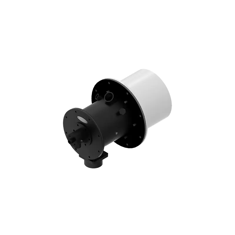
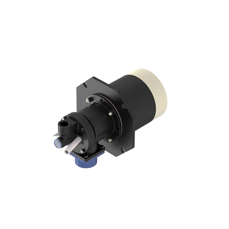
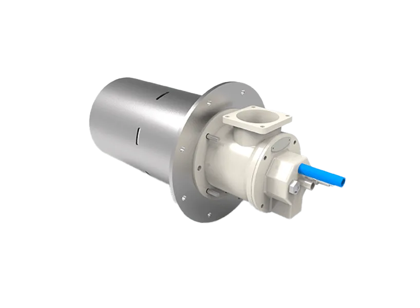
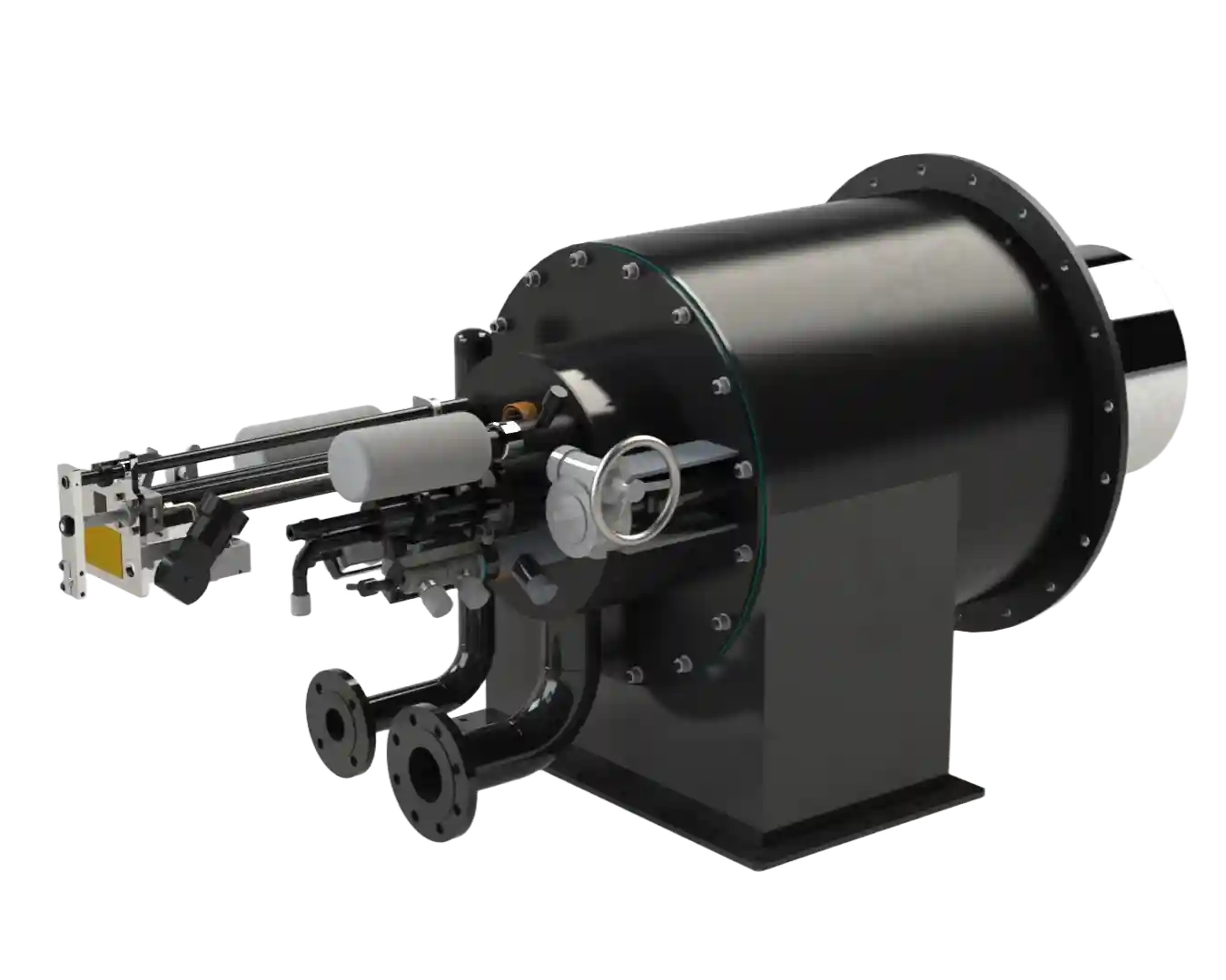
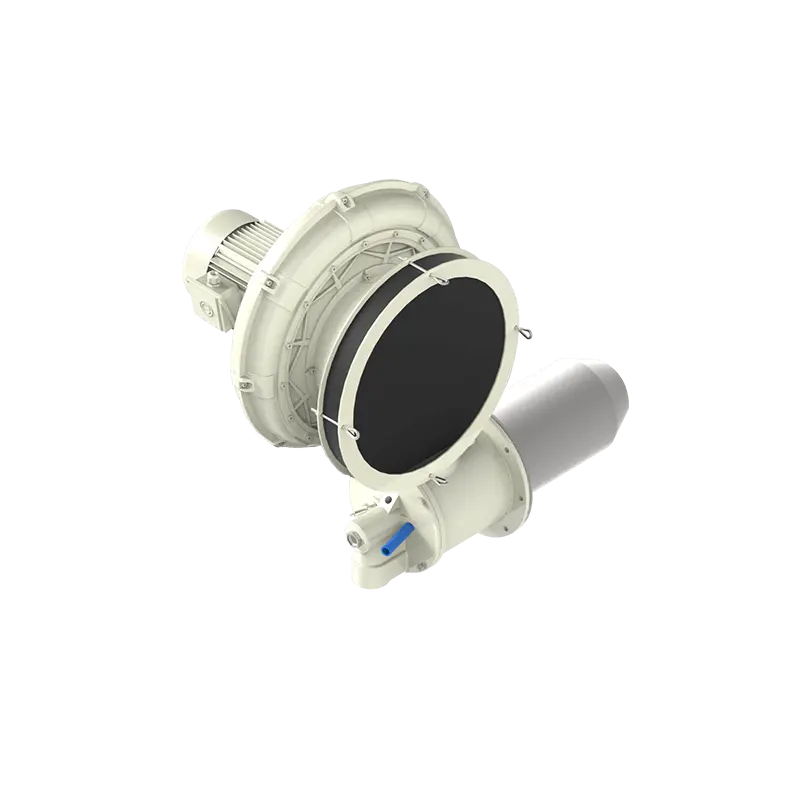
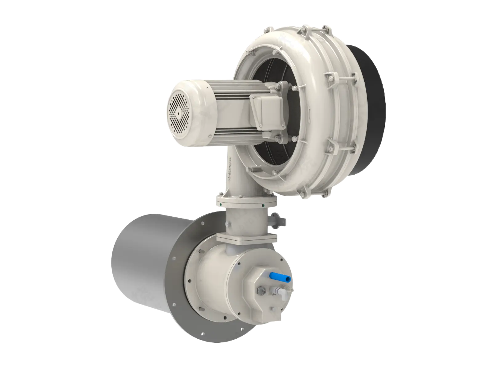
DYDTEC Combustion's industrial gas burners are designed with different flame speeds, flame lengths, and power levels for different industrial heating applications. They are used in industrial furnaces and combustion systems for heating, incineration, curing, drying, melting, and other processes.
Flame momentum determines how strongly the flame and combustion gases penetrate into the furnace.
A high-momentum flame can travel farther and influence a larger volume of the furnace.
This can be beneficial in a large furnace, but it can also increase the risk of:
Wall impingement
Workpiece impingement
Flame interaction
Localized overheating
A lower-momentum flame may be more appropriate for a compact heating zone.
Therefore, burner location should be selected based on the combination of:
Flame momentum + Flame length + Furnace dimensions + Target heating zone
When a furnace uses multiple burners, the burners should be treated as a coordinated system.
The objective is not simply to divide the required thermal capacity by the number of burners.
For example, four burners installed at four convenient positions may produce a less uniform thermal field than four burners specifically arranged to generate balanced gas circulation.
When multiple burners are used, engineers should consider:
Burner spacing
Burner elevation
Burner angle
Flame overlap
Flame interaction
Furnace-wall clearance
Workpiece clearance
Exhaust location
Heating-zone boundaries
The final arrangement should create a coordinated combustion field.
Opposing burner arrangements can be useful in some furnace geometries, but they should not be applied automatically.
If opposing flames are properly designed, they can interact with the furnace atmosphere and contribute to heat distribution.
However, excessive flame interaction may create:
Localized high-temperature zones
Flame instability
Unwanted recirculation
Increased turbulence
Uneven heat distribution
Whether opposing burners are appropriate depends on burner characteristics, furnace dimensions, firing rate, and the desired gas-flow pattern.
Symmetry can be useful when the furnace and process are symmetrical.
A symmetrical burner arrangement may help produce a balanced thermal field.
However, thermal symmetry is more important than mechanical symmetry.
If the workpiece arrangement, exhaust system, heating load, or furnace geometry is asymmetric, a perfectly symmetrical burner layout may not produce a symmetrical temperature field.
Therefore, burner placement should follow the actual thermal requirements rather than symmetry alone.
The relationship between the burner and exhaust outlet is extremely important.
The exhaust system creates a gas-flow path through the furnace.
If the burner is installed too close to the exhaust, hot combustion gases may be drawn toward the exhaust before effectively transferring heat to the workpiece.
This can reduce the utilization of furnace volume.
In some cases, it may also affect:
Flame development
Furnace temperature
Combustion stability
Heat-transfer efficiency
Local oxygen concentration
Therefore, burner location and exhaust location should be designed together.
The basic objective is to ensure that combustion gases travel through the intended heating zone before leaving the furnace.
Installing burners close to furnace doors can create several challenges.
Frequent door opening can introduce cold air into the furnace and disturb the local thermal field.
A burner located too close to the door may also experience changing flow conditions during loading and unloading.
Potential consequences include:
Flame disturbance
Local temperature fluctuations
Increased heat loss
Uneven heating
Unstable combustion conditions
In some furnace designs, burners can still be installed near doors if the thermal and flow conditions are properly considered.
The key is to prevent the door-opening process from repeatedly disrupting the intended combustion environment.
Furnace pressure influences combustion and flame behavior.
The relationship between burner position and furnace pressure should therefore be considered during installation.
Pressure differences can affect:
Air infiltration
Flame stability
Combustion-gas movement
Heat loss
Flame trajectory
A burner installed in a region with strong local gas flow may behave differently from a burner installed in a relatively stable region.
Therefore, burner location should be evaluated together with furnace pressure and exhaust-system design.
Temperature uniformity is often the most important criterion when determining burner position.
A furnace can have the correct total thermal capacity but still produce poor temperature uniformity if the burners are badly positioned.
For example:
Too concentrated → Hot spots
Too widely separated → Cold zones
Poor angle → Uneven heat distribution
Poor exhaust location → Uneven gas circulation
Poor burner elevation → Vertical temperature gradient
The objective is to distribute combustion energy throughout the required process zone.
Burner position can indirectly affect fuel consumption.
If heat is distributed efficiently throughout the furnace, a larger proportion of the generated thermal energy can contribute to the actual process.
If combustion gases leave the furnace too quickly or large areas of the furnace remain poorly heated, additional fuel may be required to achieve the target process temperature.
However, fuel consumption is determined by the complete furnace system, including:
Burner efficiency
Excess air
Furnace insulation
Furnace pressure
Exhaust losses
Heat-transfer efficiency
Workpiece loading
Process temperature
Burner control
Therefore, burner position should be considered one part of overall energy optimization rather than treated as an independent fuel-saving device.
Low-NOx burner installation requires additional attention to the combustion environment.
Low-NOx burners may use technologies such as controlled mixing, staged combustion, internal recirculation, or other combustion strategies.
The burner must therefore be installed in a position that allows its designed combustion process to develop correctly.
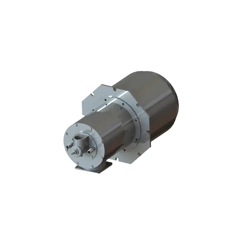
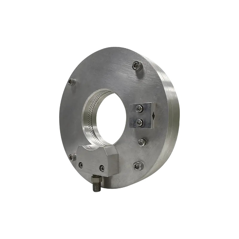
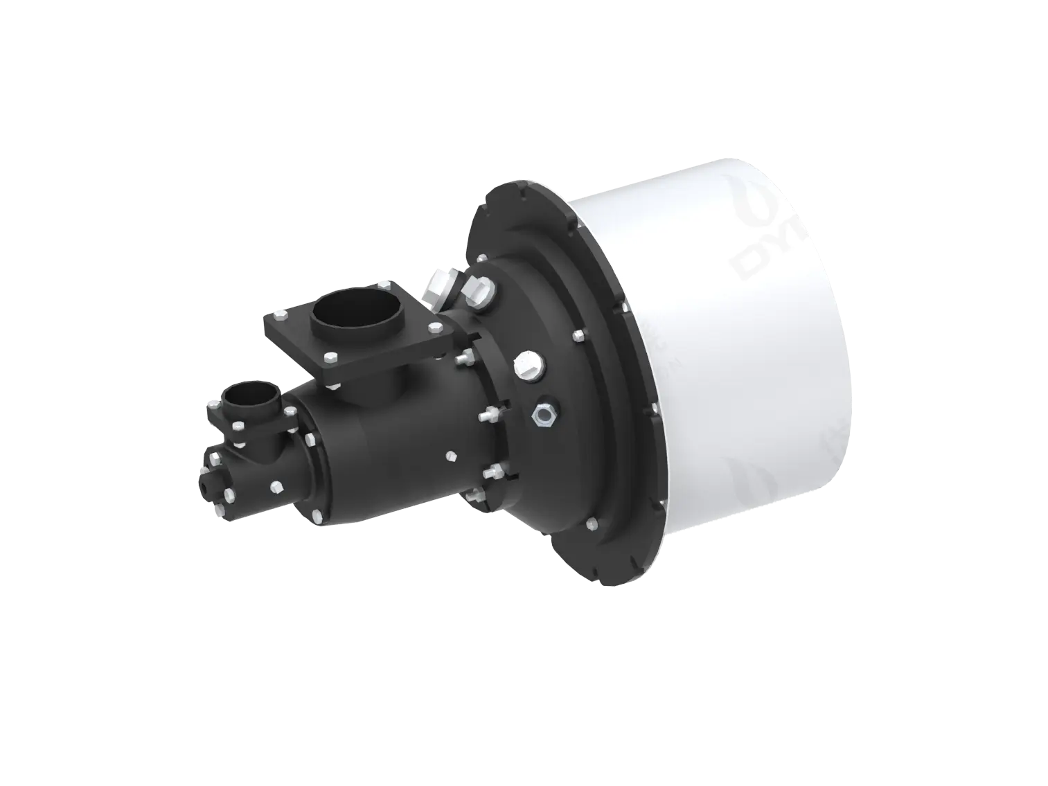
DYDTEC Combustion produces low-NOx burners for applications including hot-air furnaces, drying furnaces, preheating furnaces, ceramic kilns, glass tempering furnaces, heat-treatment furnaces, waste-gas incineration systems, and thermal oxidizers.
The correct installation position should be determined together with the burner design rather than simply replacing an existing burner without reconsidering the combustion field.
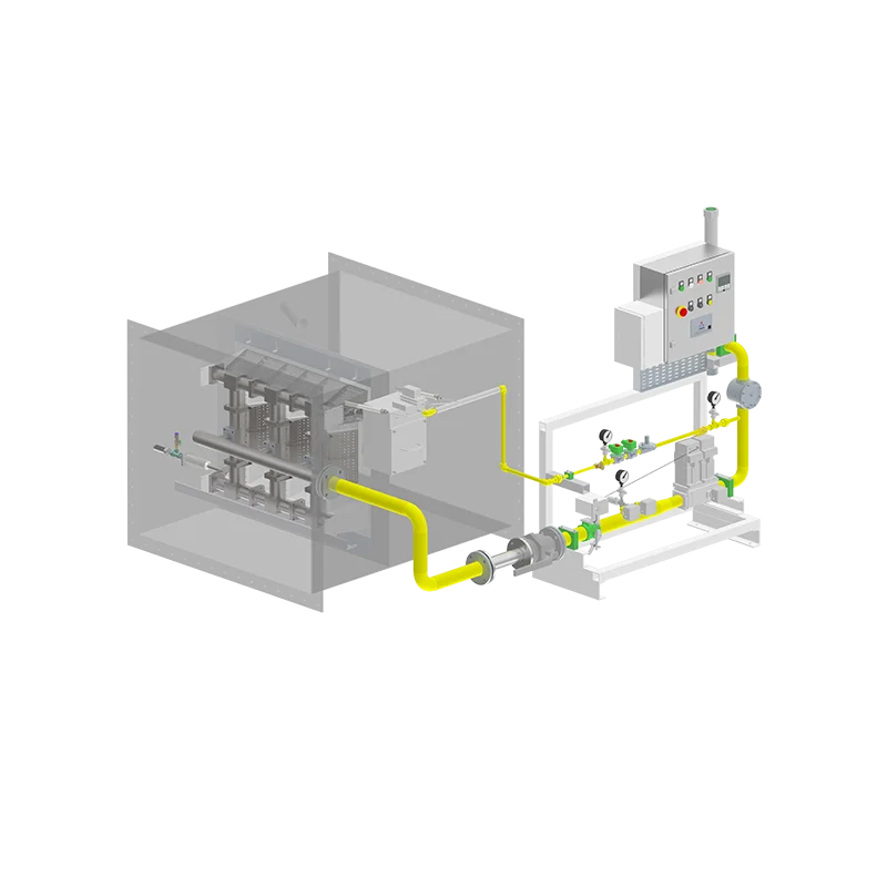
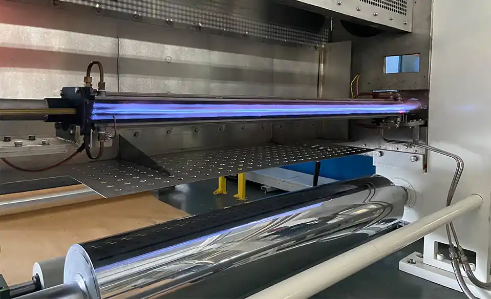
Linear burners are different from conventional point-type industrial burners.
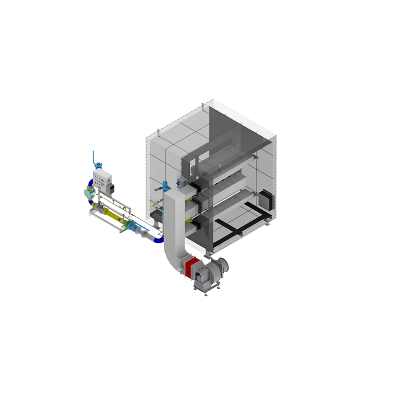
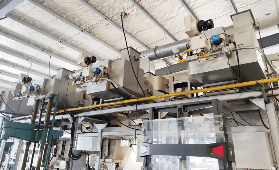
They are commonly integrated into air ducts or hot-air systems to provide large-area and relatively uniform heat distribution.
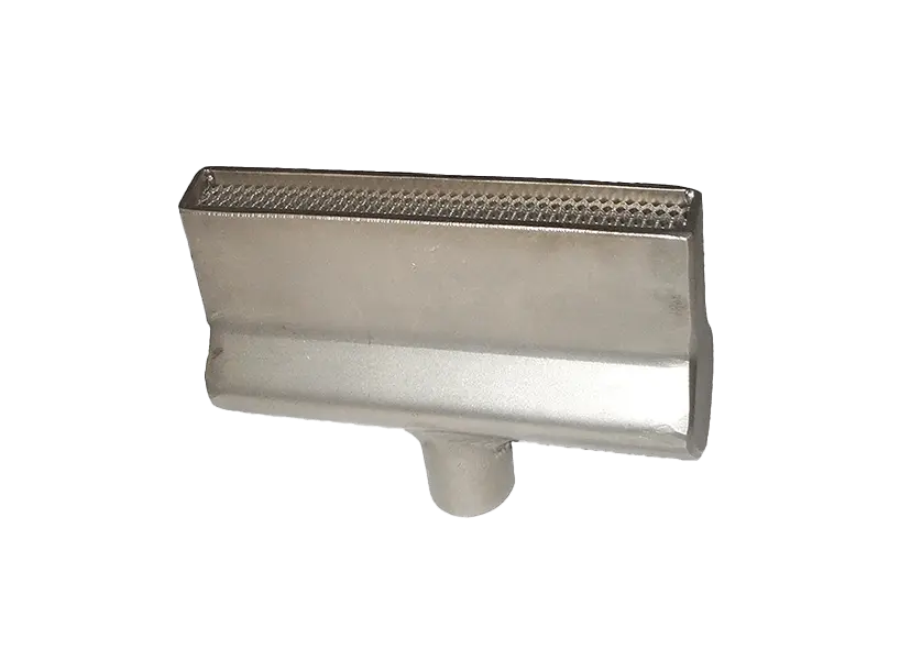
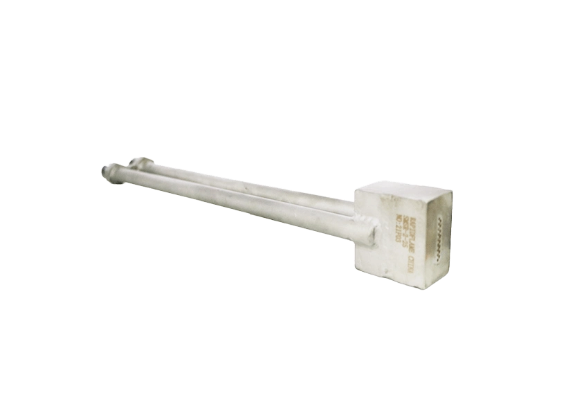
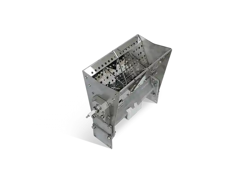
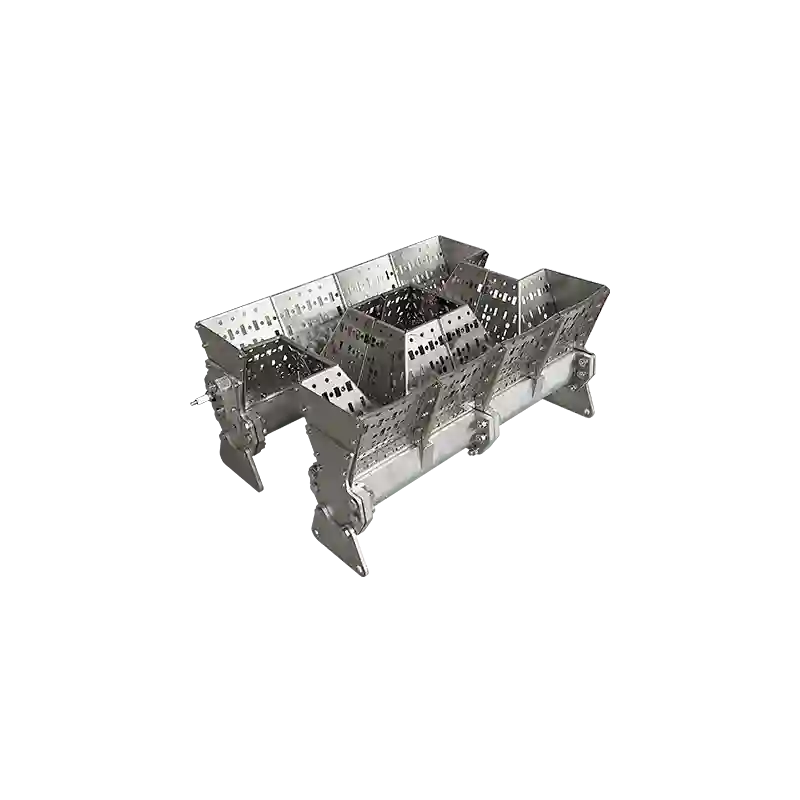
DYDTEC Combustion's linear burners are designed for large-area heat input inside air ducts and are used in industrial drying, industrial air conditioning, HRSG supplementary heating, grain drying, malt drying, baking, air dryers, chemical dryers, fresh-air heating boxes, curing, and metal forming applications.
For this type of application, the installation position should be determined based on:
Airflow direction
Duct dimensions
Air velocity
Required outlet temperature
Burner heat-release distribution
Mixing distance
Downstream equipment
The objective is to ensure that heat is mixed with the process air effectively before reaching the downstream process.
Industrial drying systems often require uniform hot-air distribution rather than direct flame heating.
In such systems, the burner may be integrated into a hot-air furnace or air-heating section.
The position should provide sufficient distance and mixing conditions for the combustion heat to become part of the process-air stream.
This is particularly important when the process requires:
Uniform product temperature
Stable drying temperature
Clean process air
Controlled moisture removal
Low-temperature operation
Heat-treatment furnaces generally require high temperature uniformity.
Burners should therefore be positioned to avoid creating strong local thermal gradients.
Important considerations include:
Workpiece arrangement
Furnace-zone dimensions
Flame length
Flame direction
Burner spacing
Furnace-wall clearance
Exhaust location
Temperature measurement points
The burner arrangement should allow the furnace to maintain the required temperature profile rather than simply maximize local heat release.
Melting furnaces typically require high heat input, but the location of that heat input is critical.
The burner position should be selected according to:
Furnace geometry
Material location
Melt surface
Refractory structure
Required heat flux
Exhaust location
The flame should be controlled so that heat is transferred efficiently without creating unnecessary refractory overheating or unwanted localized thermal loading.
For melting applications, burner position is therefore part of the overall thermal design.
Flame-treatment systems are different from conventional furnace heating systems.
The purpose may be to expose a material surface to a controlled flame for:
Surface activation
Improved adhesion
Deburring
Stress relief
Preheating
Surface modification
In these systems, the burner may be installed at a fixed position relative to a conveyor or mounted on a robot.
DYDTEC Combustion's flame-treatment equipment can use fixed flame heads for continuous processing of flat materials such as plastic sheets, metal sheets, films, and paper. Robot-mounted flame nozzles can also provide rotating or multi-angle treatment for pipes, bottles, and irregular components.
In this case, burner position is determined by the required flame-to-surface relationship.
A practical burner-positioning process can be divided into several steps.
First determine what the burner is expected to accomplish.
Is the objective:
Uniform furnace heating?
Rapid heating?
Localized heating?
Drying?
Melting?
Heat treatment?
Air heating?
Flame treatment?
The answer determines the type of burner arrangement required.
Measure or define:
Furnace length
Furnace width
Furnace height
Heating zones
Workpiece location
Internal structures
Furnace openings
Exhaust location
Determine:
Burner capacity
Flame length
Flame shape
Flame velocity
Flame momentum
Turndown ratio
Fuel type
Combustion-air requirements
Select a position that provides sufficient clearance for the flame and allows combustion gases to enter the intended heating zone.
Verify that the flame will not unintentionally hit:
Furnace walls
Refractory
Workpieces
Rollers
Supports
Other burners
Evaluate how combustion gases will move from the burner toward the exhaust.
The desired flow path should maximize useful heat transfer before the gases leave the furnace.
Measure or simulate the expected thermal field.
If necessary, adjust:
Burner position
Burner angle
Burner spacing
Burner capacity
Heating-zone control
After installation, actual furnace temperature measurements and flame observations should be compared with the design assumptions.
For complex systems, thermal and CFD simulation can provide additional support during design.
DYDTEC Combustion has developed combustion and thermal digital-twin simulation capabilities and CFD thermal simulation technology as part of its technical development.
Yes, whenever possible.
For OEM furnace manufacturers, burner location should ideally be defined during the furnace-design stage.
Waiting until the furnace has already been fabricated can create problems because the final burner position may be constrained by:
Structural members
Refractory thickness
Piping
Access doors
Exhaust ducts
Maintenance space
Existing equipment
Early combustion-system design allows the furnace and burner to be developed together.
This makes it easier to coordinate:
Furnace geometry + Burner position + Burner angle + Exhaust + Control system
rather than trying to fit the burner into an already completed furnace.
Mechanical convenience does not guarantee good combustion performance.
This can increase the risk of direct flame impingement and localized overheating.
Poor coordination between burner and exhaust can cause hot gases to leave the furnace before useful heat transfer occurs.
Identical burner elevation is not always appropriate for a furnace with significant vertical temperature differences.
A burner with a long flame needs sufficient space to develop.
Multiple burners can interact with each other, changing the overall combustion field.
Moving a burner can change flame trajectory, gas circulation, heat distribution, and potentially combustion behavior.
Burner selection and positioning should ideally be integrated into the furnace design from the beginning.
It is difficult to determine the correct burner location without knowing which burner will be installed.
Similarly, it is difficult to select the correct burner without understanding where it will operate.
These three factors are closely connected:
Burner Selection → Burner Characteristics → Burner Position → Flame Trajectory → Furnace Thermal Field
For example, a burner with a long, high-momentum flame may require a different installation position from a compact burner.
A linear burner integrated into an air duct has a completely different installation logic from a point-type gas burner.
A flame-treatment burner mounted on a robot has a different positioning requirement from a burner installed permanently in a furnace wall.
Therefore, burner selection and installation should be treated as one engineering problem.
For complex industrial applications, a burner manufacturer should ideally evaluate more than the burner's nominal capacity.
The technical evaluation may include:
Furnace geometry analysis
Burner selection
Flame-length analysis
Burner-position recommendations
Burner-angle recommendations
Burner-spacing design
Combustion-air requirements
Fuel-system requirements
Exhaust-flow analysis
Temperature-distribution analysis
CFD or thermal simulation
Commissioning support
Customized burner development
DYDTEC Combustion has more than 100 burner models covering more than 200 application scenarios and provides customized combustion solutions according to different project requirements.
Its product range covers gas burners, linear burners, low-NOx burners, oil burners, oxygen burners, hydrogen burners, low-calorific-value burners, flame-treatment burners, and combined-fuel burners.
There is no universal best location. The burner should be positioned according to furnace geometry, flame characteristics, workpiece location, heating requirements, burner arrangement, and exhaust-gas flow.
In many furnace designs, yes. However, the exact wall position must be selected based on flame trajectory, clearance, heat distribution, and furnace gas flow.
There is no universal distance. The appropriate distance depends on flame length, flame momentum, heat-release intensity, workpiece material, and process requirements.
Not necessarily. Many furnace processes require a uniform thermal environment rather than direct flame impingement.
It can be possible, but the burner and exhaust locations must be coordinated. If hot gases are extracted too quickly, heat may not be effectively transferred to the process.
Large furnaces often require multiple burners distributed according to heating zones, furnace geometry, workpiece arrangement, and required temperature uniformity.
Not always. Symmetry can be useful, but burner positioning should ultimately follow the thermal requirements of the furnace.
It can indirectly affect energy utilization by influencing heat distribution and exhaust losses, although overall fuel consumption depends on the complete furnace and combustion system.
Yes. The local gas-flow environment around the burner can influence flame development and stability.
Ideally, yes. Early integration of burner and furnace design can reduce installation constraints and help optimize the thermal field.
Yes. CFD and thermal simulation can help evaluate flame trajectories, combustion-gas circulation, temperature distribution, and potential hot spots before finalizing the design.
Potentially, but changing the installation position can change the surrounding flow and thermal environment. The burner and furnace should be evaluated together before repositioning.
A burner should be installed where its flame and combustion gases can create the required thermal field—not simply where the burner is easiest to mount.
The correct installation position depends on the interaction between:
**Furnace geometry
Burner characteristics
Workpiece position
Burner angle
Burner spacing
Exhaust location
Gas circulation
Temperature requirements**
A poorly positioned burner can create hot spots, cold zones, flame impingement, uneven heating, refractory problems, and inefficient heat utilization even when the burner itself has sufficient capacity.
For this reason, burner installation should be considered during the early stages of furnace and combustion-system design.
The most reliable approach is to select the burner and determine its position as part of the same engineering process:
Select the right burner → determine the right position → establish the right flame trajectory → create the right thermal field.
With more than 100 burner models, more than 200 application scenarios, and a product portfolio covering gas, linear, low-NOx, oil, oxygen, hydrogen, low-calorific-value, flame-treatment, and combined-fuel burners, DYDTEC Combustion provides customized industrial combustion solutions for different process requirements.