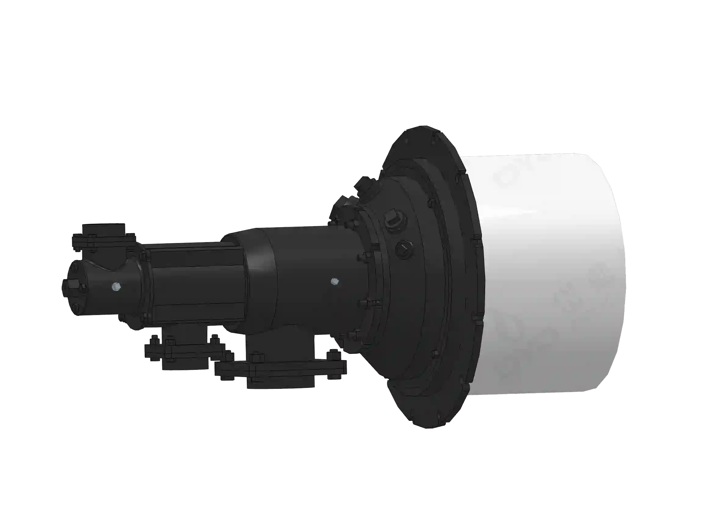
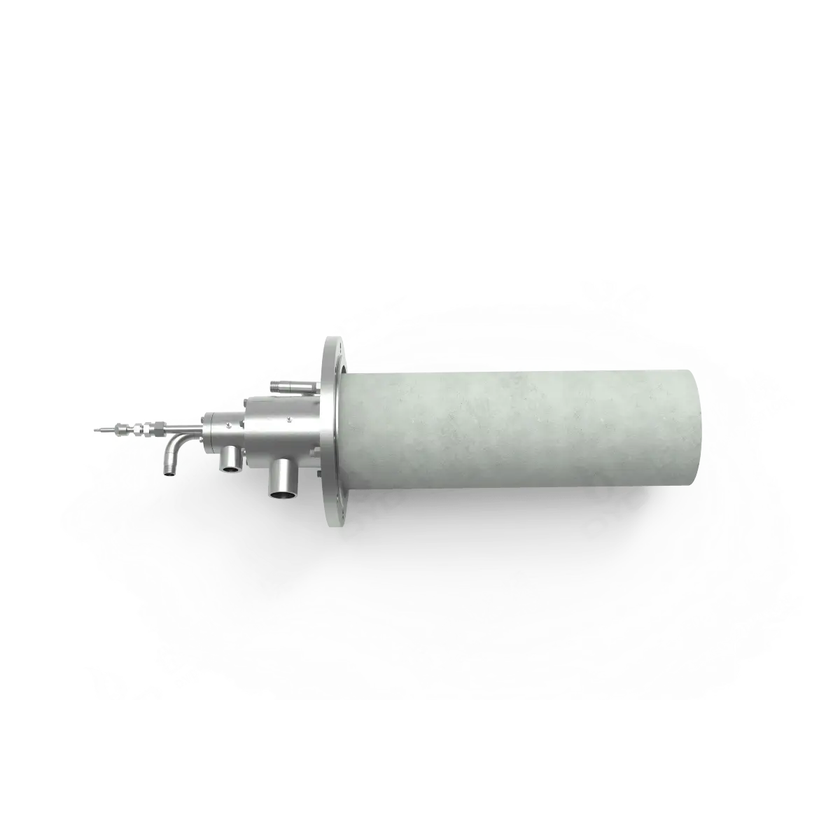
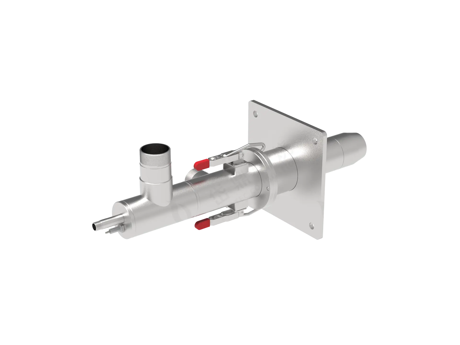
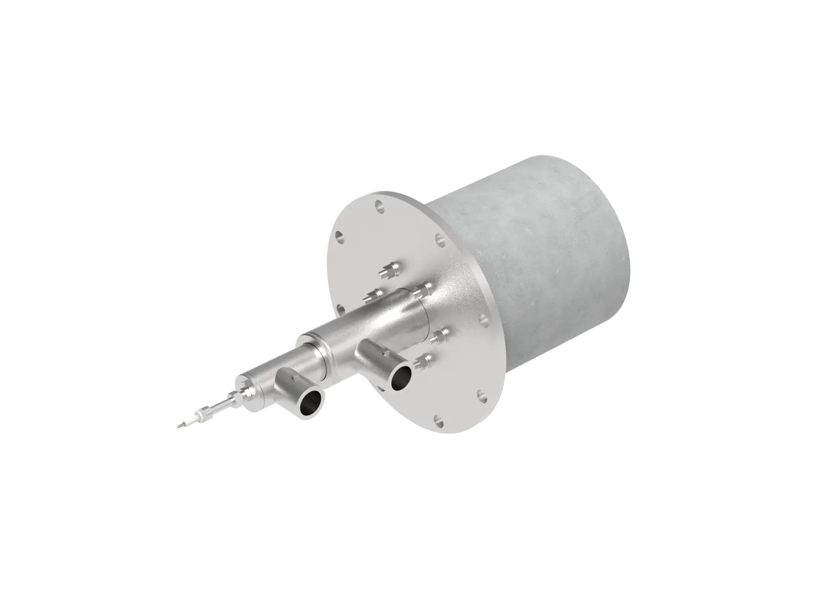
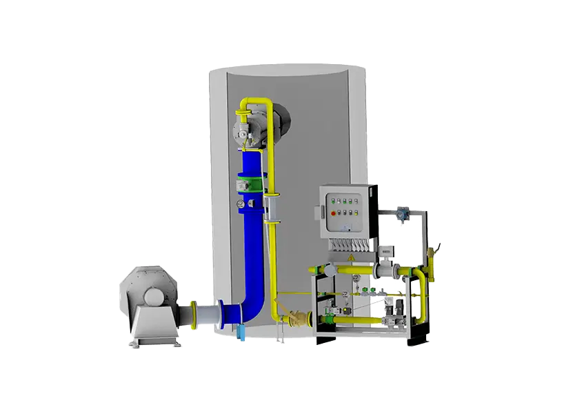
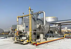
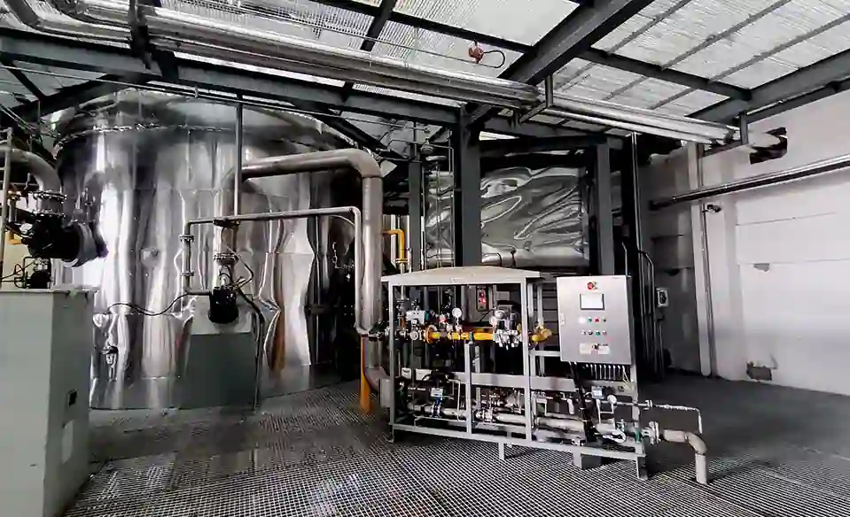
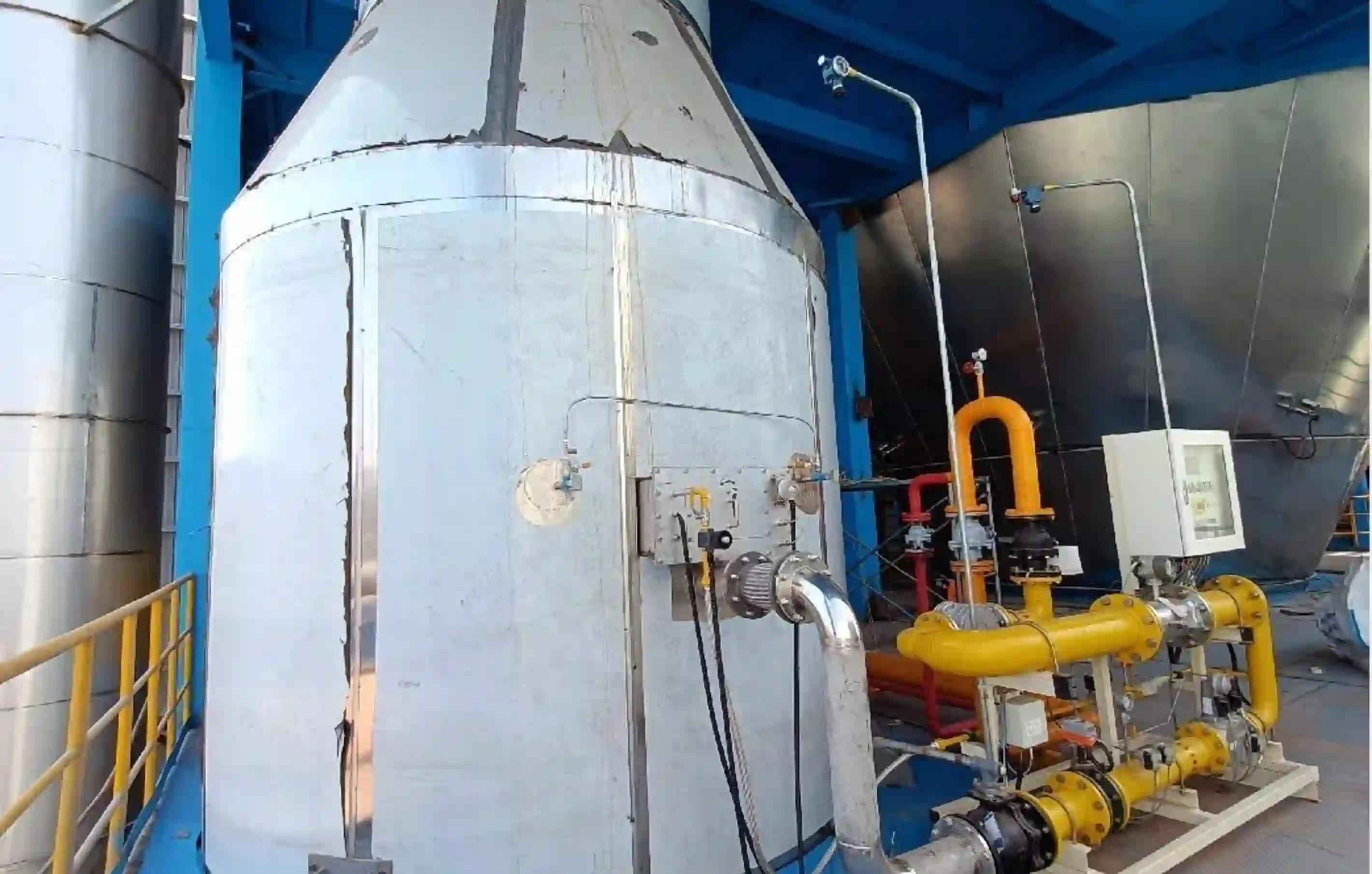
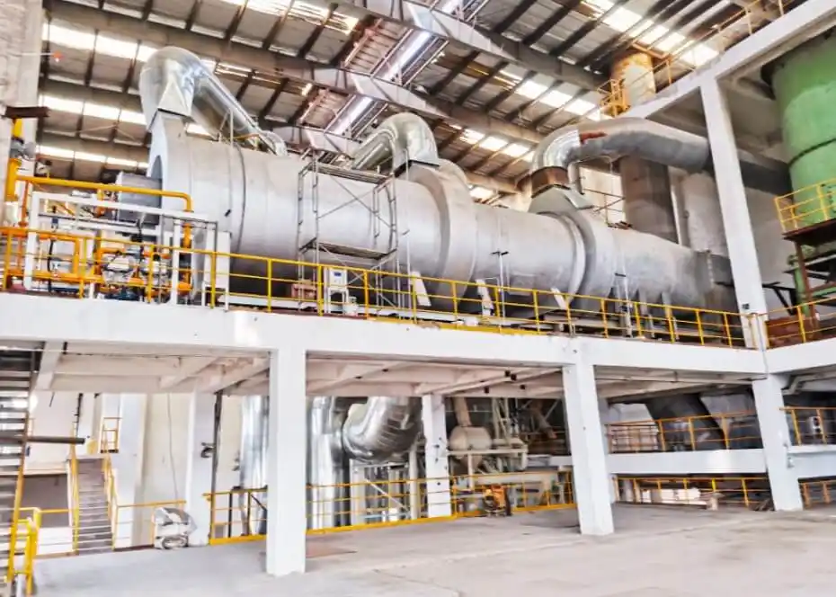
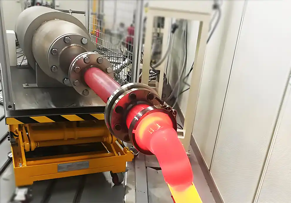
The shape of a combustion chamber has a direct influence on how a burner flame develops, how hot gases move, and how heat is distributed throughout industrial equipment.
Two chambers can have exactly the same volume and the same burner capacity but produce very different combustion results simply because their shapes are different.
A long and narrow chamber, a short and wide chamber, a tall vertical chamber, and a compact cylindrical chamber create different flow fields around the flame.
This is why burner selection should not be based only on thermal capacity or furnace volume.
The more complete relationship is:
Burner → Flame → Chamber Shape → Gas Flow → Heat Transfer → Process Performance
The key principle is:
A burner should be matched to the geometry of the chamber in which it operates.
A burner releases fuel and combustion air into a defined physical space.
That space determines:
How far the flame can travel
How the flame expands
Where combustion gases circulate
How quickly hot gases reach the chamber walls
How heat reaches the product
Where recirculation zones form
How gases eventually leave through the exhaust
The chamber shape therefore influences both combustion behavior and heat-transfer behavior.
A burner that performs well in one chamber may need a different flame configuration when installed in another chamber, even if the required heat input remains unchanged.
Yes.
Flame length is one of the most important characteristics that needs to be considered when matching a burner to chamber geometry.
A long, narrow chamber may provide a long path for flame development.
A short chamber provides much less distance before the flame reaches a wall or another structure.
For example:
Long chamber + long flame
can potentially provide good flame development.
But:
Short chamber + long flame
may increase the risk of flame impingement.
Similarly:
Large chamber + very short flame
may concentrate heat close to the burner and leave other areas insufficiently heated.
Therefore, the objective is not to achieve the longest possible flame.
The objective is to achieve a flame shape that fits the chamber and the process.
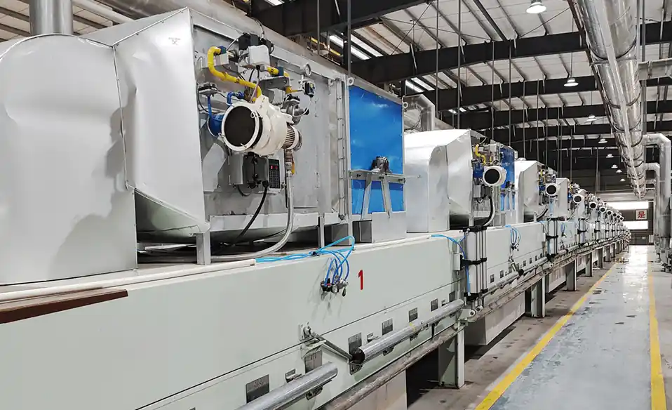
Long and narrow chambers are common in continuous industrial heating equipment.
Examples include:
Continuous furnaces
Long drying ovens
Heat-treatment lines
Preheating tunnels
Continuous heating chambers
In this geometry, the burner may be installed at one end and fire along the length of the chamber.
This configuration places particular importance on:
Flame length
Flame momentum
Burner angle
Gas circulation
Exhaust position
A long flame can provide good longitudinal heat coverage.
However, excessive flame length may cause the flame to approach the opposite wall or interact with the product.
For long chambers, burner placement and exhaust location should therefore be considered together.
A short and wide chamber presents a different challenge.
The available flame-development distance may be limited, while the required heating area can be relatively large.
A concentrated flame may create a local hot zone near the burner.
Possible solutions include:
Multiple burners
Distributed burner placement
Different flame patterns
Increased gas recirculation
Tangential firing
Optimized burner angles
The correct solution depends on the process and thermal requirements.
Simply increasing burner capacity is not necessarily the best way to improve heating.
Vertical chambers can create strong buoyancy effects because hot combustion gases naturally rise.
This can influence:
Flame trajectory
Hot-gas circulation
Temperature stratification
Exhaust flow
Heat distribution
A burner firing upward may take advantage of natural buoyancy.
However, if the process requires uniform temperature around a product located at different elevations, buoyancy can also create temperature differences.
The burner, chamber geometry, and exhaust arrangement should therefore be designed as a complete flow system.
Cylindrical chambers can create different circulation patterns from rectangular chambers.
Depending on burner arrangement, combustion gases may circulate around the central axis.
This can be useful for applications requiring:
Circumferential heating
Radial heat distribution
Rotational thermal flow
Uniform heating around a central product
However, the result depends heavily on burner orientation and exhaust configuration.
A cylindrical chamber does not automatically produce uniform heating.
Chamber width determines the amount of lateral space available for flame expansion and hot-gas circulation.
If the chamber is narrow, the flame may interact with the side walls sooner.
If the chamber is wide, the flame may have more room to expand.
However, excessive width can also reduce the effectiveness of a concentrated flame when the process requires broad heat coverage.
This is why engineers should evaluate:
Flame Width + Chamber Width + Product Position
rather than considering chamber width alone.
Chamber height becomes particularly important for vertically oriented flames and high-temperature applications.
A tall chamber may provide additional space for:
Flame development
Hot-gas rise
Recirculation
Temperature stratification
A low chamber provides less vertical clearance.
If the burner fires upward inside a low chamber, the flame may approach the roof or refractory too quickly.
In contrast, a downward-firing burner in a tall chamber may require careful consideration of flame termination and exhaust flow.
Absolutely.
Temperature uniformity depends on how heat is distributed throughout the chamber.
Chamber geometry influences:
Gas circulation
Dead zones
Recirculation zones
Wall heat transfer
Product exposure
Exhaust flow
A chamber with a poorly designed flow path can produce:
Hot Zone → Cold Zone → Hot Zone
even when the burner itself is operating correctly.
This is why temperature-uniformity problems cannot always be solved by changing the burner.
Sometimes the underlying problem is chamber geometry or airflow.
Direct flame impingement should generally be avoided unless the process specifically requires controlled flame contact.
Potential consequences include:
Localized overheating
Refractory thermal stress
Wall damage
Product overheating
Uneven temperature distribution
Changes in flame behavior
The risk becomes greater when:
The chamber is too small
The flame is too long
The burner angle is incorrect
The burner output is excessive
Internal structures obstruct the flame
For this reason, flame clearance should be checked at both minimum and maximum firing conditions.
Burner angle determines the initial direction of the flame.
Changing the angle can alter:
Flame-wall distance
Flame trajectory
Gas circulation
Heat distribution
Product exposure
For example, a burner firing directly toward a wall may create a concentrated hot zone.
Changing the angle can redirect the flame into a larger circulation path.
In some industrial furnaces, burners may be arranged tangentially to create a swirling flow pattern.
Therefore, burner angle is often a geometry-dependent design parameter rather than a fixed burner specification.
Burner position determines where heat enters the chamber.
Possible locations include:
End wall
Side wall
Roof
Floor
Multiple side positions
Opposite sides
Different heating zones
The best position depends on the required thermal field.
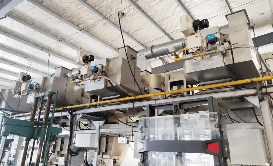
For example, a long chamber may benefit from burners distributed along its length.
A compact chamber may require fewer burners with carefully selected flame characteristics.
Chamber geometry can influence the number of burners required.
A single burner may be suitable when:
The chamber is relatively compact
Heat distribution is simple
The required thermal load is moderate
Multiple burners may be more appropriate when:
The chamber is long
Heating zones are required
Product loading is distributed
Temperature uniformity is critical
Independent zone control is needed
The important point is:
Burner quantity should be determined by thermal distribution requirements, not chamber volume alone.
Yes.
The chamber shape and exhaust location work together to determine the path of combustion gases.
Consider:
Burner → Flame → Hot Gas → Exhaust
If the exhaust is located too close to the burner, hot gases may leave before adequately transferring heat to the chamber or product.
If the exhaust is located too far away, excessive temperature gradients or pressure differences may develop.
The optimal exhaust position depends on:
Chamber geometry
Burner location
Product location
Required gas circulation
Exhaust flow
Chamber geometry influences gas-flow resistance and circulation paths, which can affect pressure distribution.
However, chamber shape alone does not determine furnace pressure.
Pressure is also affected by:
Combustion-air supply
Fuel input
Exhaust fan
Exhaust duct
Leakage
Dampers
Recirculation
The combustion chamber should therefore be evaluated as part of the complete air and exhaust system.
Heat transfer inside a combustion chamber occurs through mechanisms including:
Convection
Radiation
Conduction through chamber structures
Direct flame radiation where applicable
Chamber geometry determines how much surface area is exposed to hot gases and how those gases move through the chamber.
A long chamber may promote extended gas-to-wall heat transfer.
A compact chamber may create higher local heat flux.
A chamber with poor circulation may leave some areas underheated regardless of burner output.
Indirectly, yes.
A poorly matched chamber can increase:
Exhaust heat losses
Wall heat losses
Temperature gradients
Overheating
Heating time
A well-designed chamber can help direct heat where it is needed.
However, fuel efficiency is determined by the complete system, including:
Burner + Air-Fuel Ratio + Furnace Insulation + Exhaust + Process Load + Control
Chamber shape is one factor within this larger system.
Drying equipment provides a good example of why chamber geometry matters.
A drying system may use a burner to generate hot air, which then flows through the drying chamber.
The system can be represented as:
Burner → Hot Air → Drying Chamber → Product → Exhaust
The chamber shape affects:
Air velocity
Air distribution
Product exposure
Residence time
Recirculation
Exhaust flow
A burner can produce the correct hot-air temperature while the drying chamber still produces uneven product drying if airflow distribution is poor.
Therefore, burner selection and drying-chamber design should be coordinated.
Heat-treatment processes often require tight temperature uniformity.
The chamber shape influences how combustion gases move around the workpiece.
Important considerations include:
Product arrangement
Burner position
Flame direction
Gas circulation
Exhaust location
Furnace insulation
Heating zones
For sensitive heat-treatment processes, the goal is not simply to reach the target temperature.
The goal is to create a controlled thermal field around the product.
At high temperatures, the consequences of poor geometry become more significant.
A concentrated flame can create high local thermal loads on:
Refractory
Furnace walls
Product
Fixtures
Heat-resistant components
High-temperature combustion systems therefore require careful consideration of:
Flame shape
Flame temperature
Burner angle
Chamber dimensions
Burner position
Gas circulation
The burner should be selected together with the chamber design.
For OEM manufacturers, chamber geometry is often determined during equipment design.
If the burner is selected after the chamber has already been finalized, the available burner options may become limited.
A better approach is:
Process Requirements
↓
Thermal Calculation
↓
Burner Selection
↓
Chamber Geometry
↓
Burner Position & Angle
↓
Air & Exhaust Design
↓
Control System
This integrated approach allows the burner and chamber to be developed together.
When asking a burner manufacturer to evaluate a combustion system, OEMs should provide:
Length
Width
Height
Internal volume
Installation position
Burner angle
Burner opening
Available space
Product position
Product dimensions
Product throughput
Required temperature
Shelves
Rollers
Baffles
Heat exchangers
Refractory structures
Exhaust location
Exhaust flow
Exhaust pressure
A chamber cross-section or 3D CAD model can be particularly useful.
A practical evaluation should consider at least four relationships.
How much heat is required?
What flame length, width, and momentum are required?
How much physical space is available for the flame and hot gases?
How will heat reach the product and leave through the exhaust?
This prevents a common mistake:
Selecting a burner based only on kW and then trying to make it fit the furnace.
The better approach is to match the burner and chamber as a thermal system.
DYDTEC Combustion develops industrial combustion solutions for different equipment structures and process conditions.
Its portfolio includes 100+ burner models covering 200+ application scenarios, providing different combustion configurations for applications with different chamber sizes, shapes, thermal loads, and operating conditions.
For an OEM project, chamber geometry can be considered together with:
Burner capacity
Flame characteristics
Burner position
Burner angle
Fuel conditions
Combustion-air supply
Exhaust conditions
Temperature-control requirements
This approach is particularly useful when a standard burner configuration cannot be directly matched to the equipment.
A standard burner may provide the required thermal capacity but still not be ideal for a particular chamber.
Customization may be required when the equipment has:
Unusual chamber dimensions
Limited installation space
Special flame requirements
Non-standard fuel
High backpressure
Tight temperature-uniformity requirements
Special burner angles
Complex heating zones
DYDTEC Combustion has a 98%+ self-developed system product rate, supporting greater flexibility when combustion equipment needs to be adapted to specific OEM equipment and process conditions.
A chamber may have sufficient volume but insufficient flame-development distance.
Two burners with the same capacity can have different flame characteristics.
A small change in firing direction can significantly affect flame-wall clearance and heat distribution.
The exhaust determines where hot gases leave the chamber.
This can create local overheating.
More burners do not automatically mean better temperature uniformity.
Late burner selection can force compromises in the equipment design.
Yes. Chamber shape affects flame development, heat distribution, gas circulation, burner positioning, and exhaust flow.
Yes. A long narrow chamber and a short wide chamber can have very different combustion and heat-transfer characteristics even when their volumes are identical.
Not necessarily. Burner capacity should be based primarily on thermal demand, while chamber geometry determines how that heat can be distributed.
Indirectly. The chamber does not change the burner’s designed flame characteristics by itself, but the available space and flow environment determine how the flame develops and interacts with the chamber.
The flame may impinge on walls, refractory, products, or internal components, potentially causing localized overheating.
Heat may become concentrated near the burner and fail to provide adequate coverage of the chamber.
Yes. Geometry affects gas circulation, recirculation zones, heat-transfer paths, and exhaust flow, all of which can influence temperature uniformity.
No. Burner quantity depends on thermal load, chamber geometry, heating zones, temperature uniformity, and control requirements.
It can influence gas-flow resistance and circulation, but furnace pressure is also determined by the air supply, exhaust system, leakage, and operating conditions.
Indirectly. Poor geometry can contribute to uneven heating, longer heating times, or higher exhaust losses, but fuel consumption depends on the complete thermal system.
At minimum, provide chamber dimensions, burner location, product position, internal structures, exhaust location, operating temperature, and required heat input.
Ideally, burner selection and chamber design should be developed together, especially for customized OEM equipment.
Neither should be considered independently. Volume describes available space, while shape determines how that space influences flame and gas flow.
Chamber shape directly affects how combustion develops inside industrial equipment.
The same burner can produce different results in different chamber geometries because flame development, gas circulation, heat transfer, and exhaust flow are all influenced by the physical shape of the combustion space.
The most effective design approach is therefore:
Process→ Thermal Load→ Burner→ Flame Characteristics→ Chamber Shape→ Airflow→ Exhaust→ Temperature Distribution
Rather than asking only:
“What burner capacity does this furnace need?”
OEM engineers should also ask:
“What flame can this chamber accommodate, and how should the combustion gases move through the equipment?”
That question leads to a more complete combustion-system design and helps reduce problems such as flame impingement, uneven heating, excessive local temperatures, and inefficient heat distribution.
For industrial OEM equipment, the burner and chamber should be designed as one thermal system—not as two independent components.