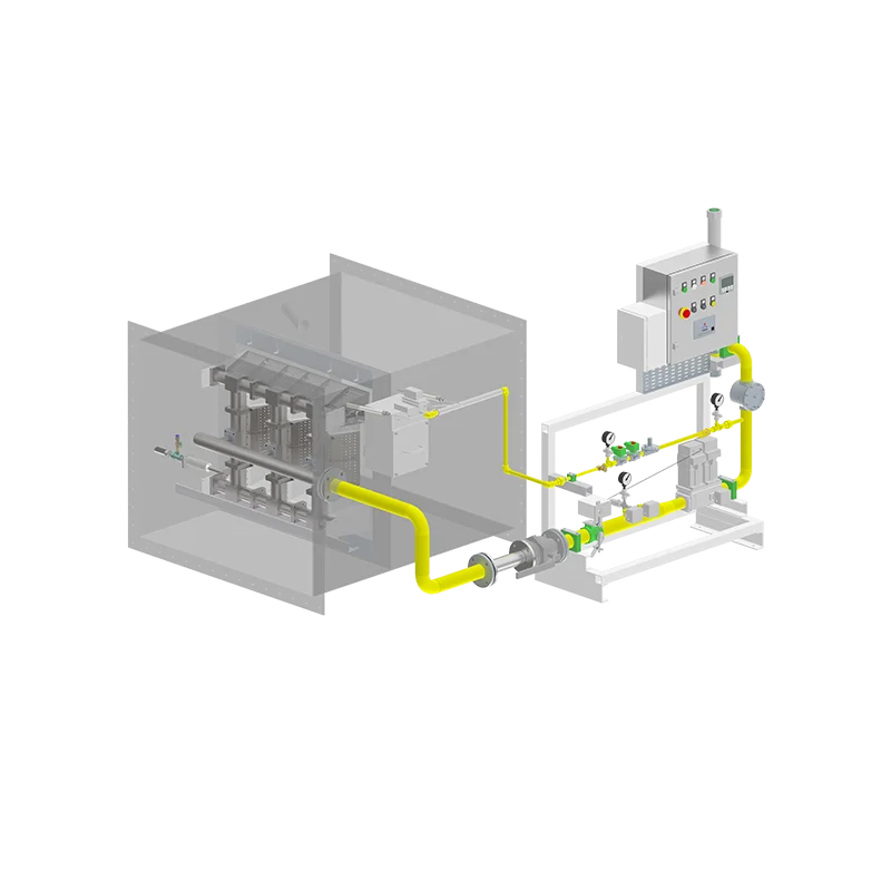
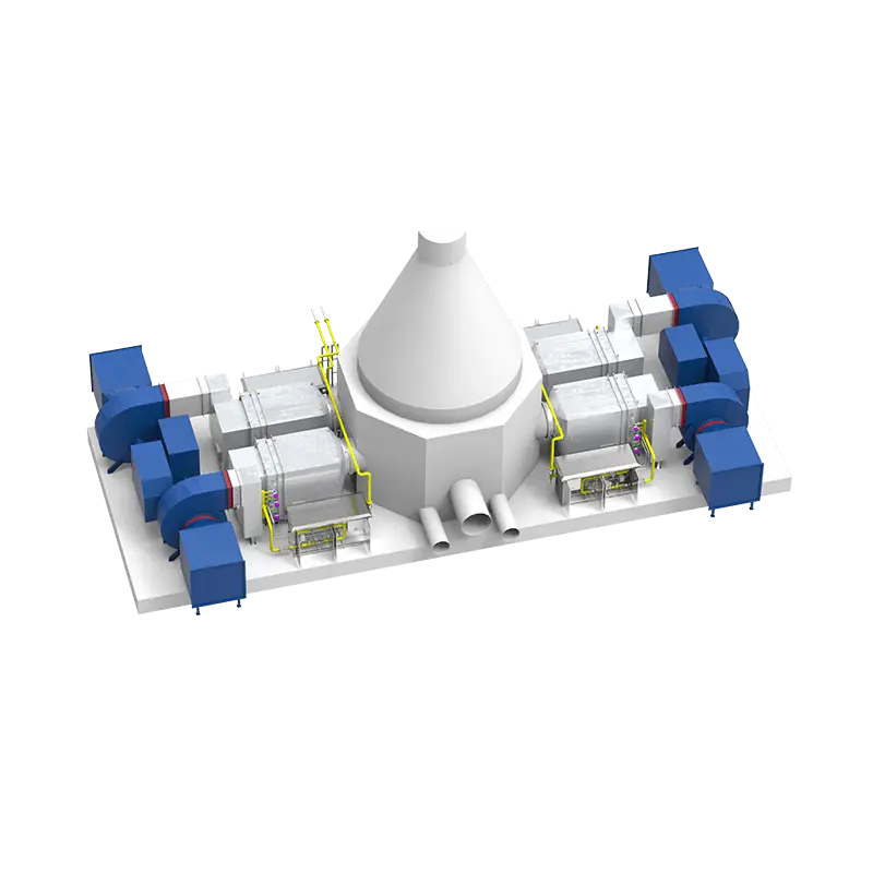
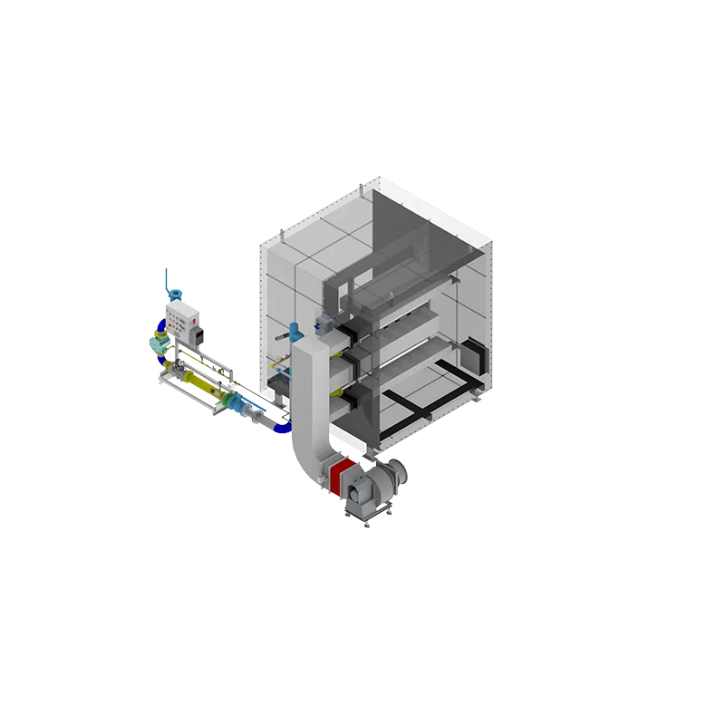
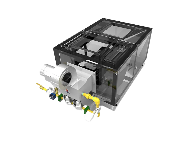
A furnace can have the right burner capacity, the correct fuel, and the required operating temperature—and still fail to achieve stable and uniform heating.
One of the reasons is airflow.
Inside an industrial furnace, air and combustion gases determine how heat moves from the burner to the furnace walls and the product. The airflow pattern influences combustion stability, flame shape, temperature distribution, heat transfer, exhaust performance, and ultimately the consistency of the industrial process.
This is why furnace airflow should not be treated simply as a matter of “how much air the blower supplies.”
The more important question is:
How does the air move through the furnace, and what does that airflow do to the flame and heat distribution?
A well-designed combustion system needs to coordinate:
Fuel + Combustion Air + Burner + Furnace Geometry + Gas Flow + Exhaust
In an industrial combustion system, airflow can refer to several different flows.
Combustion air is supplied to the burner to react with the fuel.
Its main functions are to:
Support combustion
Control the air-fuel ratio
Influence flame characteristics
Affect combustion stability
Influence emissions
Process air is used to transfer heat to the product or process.
For example, in a hot-air drying system:
Burner → Heated Air → Product → Exhaust
Process air may be much larger in volume than the combustion air required by the burner.
Some furnaces circulate hot gases back through the chamber to improve temperature uniformity and heat transfer.
These three airflows should not automatically be treated as the same thing.
Airflow affects several critical aspects of furnace performance:
Combustion stability
Flame shape
Flame temperature
Heat distribution
Temperature uniformity
Heat-transfer efficiency
Furnace pressure
Exhaust behavior
Fuel-air mixing
Emissions
A burner releases heat, but airflow determines how much of that heat is carried, mixed, transferred, and eventually removed from the furnace.
This creates a simple relationship:
Burner → Flame → Hot Gas Flow → Heat Transfer → Product
If the airflow pattern is poorly matched to the furnace, even a technically capable burner may not deliver the expected process performance.
The amount and velocity of combustion air influence how fuel mixes with air.
Changes in combustion-air conditions can affect:
Flame length
Flame width
Flame velocity
Flame stability
Flame temperature
Heat-release distribution
Too little air can result in incomplete combustion and excessive CO.
Too much air can increase excess-air losses and carry more heat out through the exhaust.
The objective is therefore not simply to maximize airflow.
The objective is to provide the appropriate air-fuel ratio for the required operating condition.
If combustion air is insufficient for the fuel input, several problems may develop.
Potential symptoms include:
Incomplete combustion
Increased CO
Unstable flame
Soot formation in some fuel systems
Reduced combustion efficiency
Abnormal flame appearance
Increased safety risk
The actual consequences depend on the fuel, burner design, operating condition, and combustion technology.
This is why air supply should be controlled together with fuel input rather than independently.
Excessive combustion air can also reduce system performance.
Additional air entering the furnace must eventually be heated.
If the excess air leaves through the exhaust, it carries sensible heat away from the furnace.
Potential consequences include:
Increased exhaust heat loss
Lower effective thermal efficiency
Lower flame temperature
Changes in flame shape
Greater exhaust volume
Therefore:
More combustion air does not automatically mean better combustion.
The correct air supply depends on the burner and process requirements.
Temperature uniformity is one of the most important reasons to control airflow.
Imagine a furnace with a burner at one end.
If hot gases travel directly from the burner to the exhaust without sufficient mixing or circulation, the furnace may develop:
Hot Zone → Cold Zone → Exhaust
The burner may be operating correctly, but the product still experiences uneven heating.
Proper airflow can help distribute heat across the chamber.
This may involve:
Gas recirculation
Controlled air movement
Multiple burners
Optimized burner angles
Proper exhaust positioning
Internal circulation paths
Long furnaces create a greater distance between the heat source and the exhaust.
If airflow is not properly designed, heat may become uneven along the furnace length.
For example:
Burner → High Temperature → Lower Temperature → Exhaust
This can be particularly important in:
Continuous furnaces
Heat-treatment lines
Drying tunnels
Preheating equipment
Continuous ovens
The burner flame and airflow should be designed so that heat reaches the required process zones rather than simply moving toward the exhaust.
Air velocity and fuel-air mixing influence flame development.
Depending on the burner technology, changes in air conditions can affect:
Flame length
Flame diameter
Flame momentum
Mixing intensity
Heat-release location
This means that airflow should be considered together with furnace dimensions.
For example:
Long flame + short chamber
may create flame-wall interaction.
While:
Short flame + large chamber
may produce insufficient heat coverage.
The correct relationship depends on the burner and furnace design.
Airflow carries thermal energy through the furnace.
Heat transfer can occur through:
Convection
Radiation
Conduction
Gas movement influences convective heat transfer and determines which surfaces and products are exposed to hot gases.
Higher gas velocity can increase convective heat transfer in some systems, but excessive velocity may also create unwanted effects.
Therefore, airflow should be optimized for the actual process rather than maximized.
Yes.
Poor airflow distribution can create localized high-temperature areas.
Possible causes include:
Burner positioned too close to the product
Excessive flame momentum
Poor gas circulation
Inadequate mixing
Incorrect burner angle
Poorly positioned exhaust
Internal obstacles
Hot spots can cause:
Product quality problems
Refractory overheating
Material deformation
Uneven drying
Uneven heat treatment
In these situations, simply reducing burner capacity may not solve the underlying problem.
The airflow pattern may need to be examined.
Yes.
Cold zones can develop when heated gases fail to reach certain areas of the furnace.
Typical causes include:
Poor circulation
Dead zones
Insufficient mixing
Excessively strong exhaust flow
Poor burner distribution
Incorrect chamber geometry
The solution may involve changing:
Burner position
Burner angle
Air distribution
Recirculation
Exhaust arrangement
Again, the problem may be airflow rather than burner capacity.
Furnace pressure is closely connected with air and gas flow.
Pressure can be influenced by:
Combustion-air supply
Fuel input
Exhaust capacity
Exhaust resistance
Furnace leakage
Dampers
Recirculation
If the exhaust system removes gases faster than the incoming air and combustion gases can replace them, furnace pressure may become negative.
If incoming flow exceeds exhaust capacity, pressure may increase.
Depending on the application, the furnace may be designed for:
Slight negative pressure
Near-atmospheric pressure
Slight positive pressure
The appropriate condition depends on the equipment and process.
Combustion cannot be evaluated independently from the exhaust system.
A simplified system is:
Fuel + Air → Combustion → Hot Gas → Exhaust
The exhaust system determines how quickly combustion gases leave the furnace.
If exhaust flow is excessive, it may:
Increase heat loss
Draw additional cold air into the furnace
Change furnace pressure
Disturb flame behavior
If exhaust capacity is insufficient, it may:
Increase furnace pressure
Affect combustion
Reduce process stability
Increase the risk of unwanted gas accumulation
Therefore, exhaust capacity should be considered together with burner airflow.
Airflow can affect fuel consumption indirectly through thermal losses.
When excess air enters the furnace, that air must be heated.
If it subsequently leaves through the exhaust, the associated heat is lost.
A simplified energy relationship is:
Fuel Input = Useful Process Heat + Furnace Heat Loss + Exhaust Heat Loss + Other Losses
Excessive airflow can increase the exhaust component.
However, reducing air below the appropriate level is not an energy-saving strategy because incomplete combustion and unstable operation can create other problems.
The objective is optimized combustion air, not minimum air.
Airflow and combustion-air distribution can influence NOx formation because combustion temperature and oxygen availability affect NOx-generation mechanisms.
Depending on burner technology, NOx reduction strategies may include:
Staged combustion
Premixed combustion
Flue-gas recirculation
Controlled excess air
Flame-temperature management
The exact approach depends on the application and burner design.
For low-NOx systems, airflow must therefore be considered as part of the combustion strategy rather than treated simply as a supply quantity.
Different burners may require different airflow characteristics.
Often require controlled combustion air and fuel mixing to maintain stable operation across the firing range.
May use specific air and fuel distribution strategies to control peak flame temperature and oxygen availability.
Require careful control of air-fuel mixing and flow conditions.
Can distribute heat across a wider area and may require uniform airflow along the burner length.
Use oxygen rather than conventional combustion air, fundamentally changing the combustion environment and exhaust-gas characteristics.
Therefore, airflow requirements should always be considered together with burner technology.
Industrial drying is an excellent example of why combustion and airflow need to be coordinated.
A burner may generate the required thermal energy, but the product is usually heated by a moving hot-air stream.
The system can be represented as:
Burner → Hot Air → Drying Chamber → Product → Moist Exhaust
The drying result depends on:
Air temperature
Air velocity
Air volume
Recirculation
Exhaust rate
Product loading
Moisture content
A high-temperature burner does not automatically produce efficient drying.
The heated air must actually reach the product in a controlled and uniform manner.
Heat-treatment applications often require tight temperature uniformity.
Airflow helps distribute heat around the product and reduce temperature differences.
Important considerations include:
Gas circulation
Burner arrangement
Recirculation
Product loading
Exhaust position
Chamber geometry
For some applications, forced circulation may be used to improve temperature uniformity.
The objective is not simply to create hot gas, but to establish a controlled thermal field around the workpiece.
In a hot-air generator, the relationship between combustion air and process air needs to be clearly understood.
The burner requires combustion air for combustion.
The system may simultaneously handle a much larger process-air flow.
A typical indirect system can be represented as:
Fuel + Combustion Air → Burner → Heat Release → Heat Transfer → Process Air
The process-air flow determines how much thermal energy is transferred into the air stream.
Therefore, burner selection should consider both the combustion side and the hot-air side.
OEM manufacturers should consider airflow during the early equipment-design stage.
Important parameters include:
Furnace dimensions
Burner capacity
Burner position
Burner angle
Combustion-air pressure
Combustion-air flow
Process-air flow
Recirculation
Exhaust flow
Exhaust location
Furnace pressure
A basic airflow diagram can help clarify the system:
Air Supply
↓
Burner
↓
Flame / Heat Release
↓
Hot Gas Circulation
↓
Product / Heat Transfer
↓
Exhaust
The actual flow pattern should be evaluated according to the equipment geometry and process.
For an OEM burner project, useful information includes:
Air source
Air pressure
Airflow
Air temperature
Blower model
Blower curve
Airflow
Temperature
Pressure
Recirculation ratio
Exhaust flow
Exhaust temperature
Exhaust pressure
Fan information
Dimensions
Operating pressure
Burner location
Exhaust location
Internal structures
Required temperature
Production capacity
Product characteristics
Temperature uniformity requirements
This information allows the burner system to be evaluated in its actual operating environment.
Poor airflow can produce problems even when the burner itself is correctly selected.
Common symptoms include:
Uneven temperature
Hot spots
Cold zones
Flame instability
Excessive exhaust temperature
High fuel consumption
Furnace-pressure fluctuations
Poor drying uniformity
Inconsistent heat treatment
Increased emissions
This is why troubleshooting should not focus exclusively on the burner.
Engineers should also examine:
Fuel + Air + Burner + Furnace + Exhaust
Sometimes—but not always.
A burner can influence airflow through:
Air velocity
Flame momentum
Fuel-air mixing
Flame shape
Heat-release distribution
However, if the fundamental problem is caused by:
Poor exhaust design
Incorrect furnace geometry
Insufficient circulation
Incorrect duct sizing
Poor air distribution
then replacing the burner alone may not solve the problem.
A combustion system should therefore be evaluated as a complete system.
DYDTEC Combustion develops industrial burners and combustion-system solutions for different industrial heating processes.
Its product portfolio includes 100+ burner models and covers 200+ application scenarios, allowing combustion configurations to be matched to different furnace geometries, thermal loads, fuels, and airflow conditions.
For OEM equipment, airflow can be considered together with:
Burner capacity
Flame characteristics
Combustion-air conditions
Furnace geometry
Exhaust conditions
Temperature-control requirements
DYDTEC Combustion has 98%+ self-developed system products, providing flexibility for applications where the burner, airflow, and equipment structure need to be coordinated rather than treated as independent components.
For OEM manufacturers, changing the combustion system after the machine has been completed can be expensive.
The burner needs to fit:
Mechanical dimensions
Fuel supply
Air supply
Exhaust system
Electrical controls
Safety interlocks
Furnace geometry
Airflow should therefore be considered before the equipment structure is finalized.
A better development sequence is:
Process Requirements→ Thermal Calculation→ Burner Selection→ Airflow Design→ Furnace Geometry→ Exhaust Design→ Control System→ Testing
This approach can reduce integration problems during commissioning.
Airflow and furnace geometry are closely connected.
The same airflow rate can behave differently in:
A long narrow chamber
A short wide chamber
A tall vertical chamber
A cylindrical chamber
This is because geometry determines:
Flow path
Residence time
Recirculation
Wall interaction
Exhaust path
Product exposure
Therefore, airflow should be designed according to the actual three-dimensional geometry of the equipment.
The most important principle is:
Airflow should be designed for the process, not simply for the burner.
The burner needs enough air to achieve stable combustion.
The furnace needs the right gas movement to achieve effective heat transfer.
The exhaust system needs the right capacity to maintain the intended furnace pressure.
The product needs the right thermal environment to achieve the required process result.
These requirements must work together.
Airflow controls how combustion air reaches the burner and how hot gases move through the furnace. It affects combustion stability, heat transfer, temperature uniformity, pressure, emissions, and energy losses.
No. Too little air can cause incomplete combustion, while excessive air can increase exhaust heat losses. The correct airflow depends on the burner and operating condition.
Incomplete combustion, increased CO, flame instability, and reduced combustion performance may occur.
Excessive air can reduce flame temperature and increase the amount of heat carried out through the exhaust.
No. Combustion air supports fuel combustion, while process air transfers heat to the product or process. Some systems use the same air stream for specific purposes, but the functions should be distinguished during system design.
Yes. Airflow determines how hot gases circulate and how heat reaches different parts of the furnace.
Yes. Poor mixing, excessive flame momentum, inadequate circulation, or unsuitable burner positioning can create localized high-temperature areas.
Yes. Dead zones, insufficient circulation, or excessive exhaust flow can prevent heated gases from reaching certain areas.
Yes. Air supply and exhaust flow directly influence furnace pressure, together with leakage and other system characteristics.
Yes, indirectly. Excessive airflow can increase exhaust heat loss, while insufficient airflow can cause incomplete combustion and unstable operation.
It can. Air distribution, excess air, combustion temperature, and combustion strategy can all influence NOx formation.
Provide combustion-air pressure and flow, blower information, process-air requirements, recirculation, exhaust flow, exhaust pressure, furnace dimensions, and burner location whenever available.
A burner redesign may help if the burner is contributing to the problem. However, airflow problems caused by furnace geometry, exhaust design, or ducting may require a system-level solution.
Yes. Burner, airflow, furnace geometry, and exhaust should ideally be considered together during the early design stage.
Airflow is one of the fundamental elements that determines how effectively a furnace converts combustion energy into useful process heat.
The burner creates the heat, but airflow determines how that heat is mixed, transported, distributed, and ultimately transferred to the product.
The complete relationship is:
Fuel→ Combustion Air→ Burner→ Flame→ Hot-Gas Flow→ Heat Transfer→ Product→ Exhaust
A furnace with a properly selected burner can still experience poor performance if its airflow is poorly designed.
For this reason, industrial furnace design should evaluate burner capacity, airflow, chamber geometry, exhaust, and process requirements as one integrated combustion system.
That is particularly important for OEM equipment, where the burner and airflow system should be considered early enough to influence the overall machine design rather than being added after the furnace structure has already been finalized.