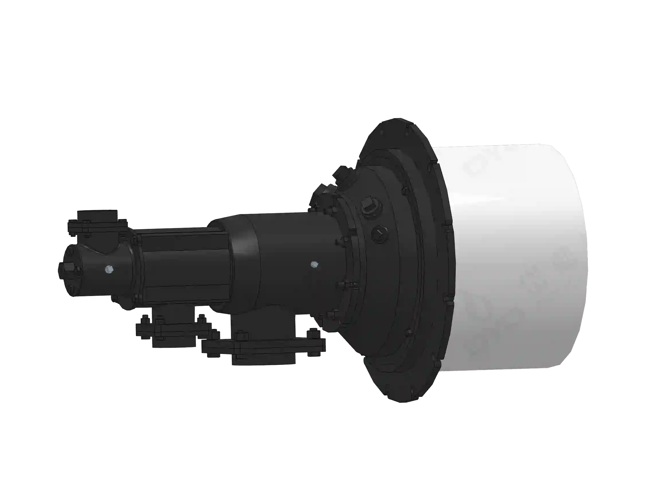
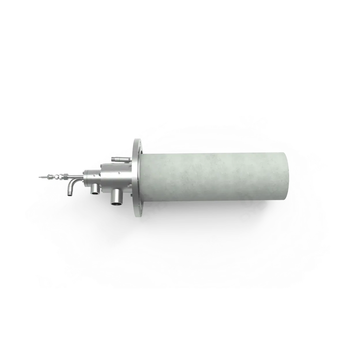
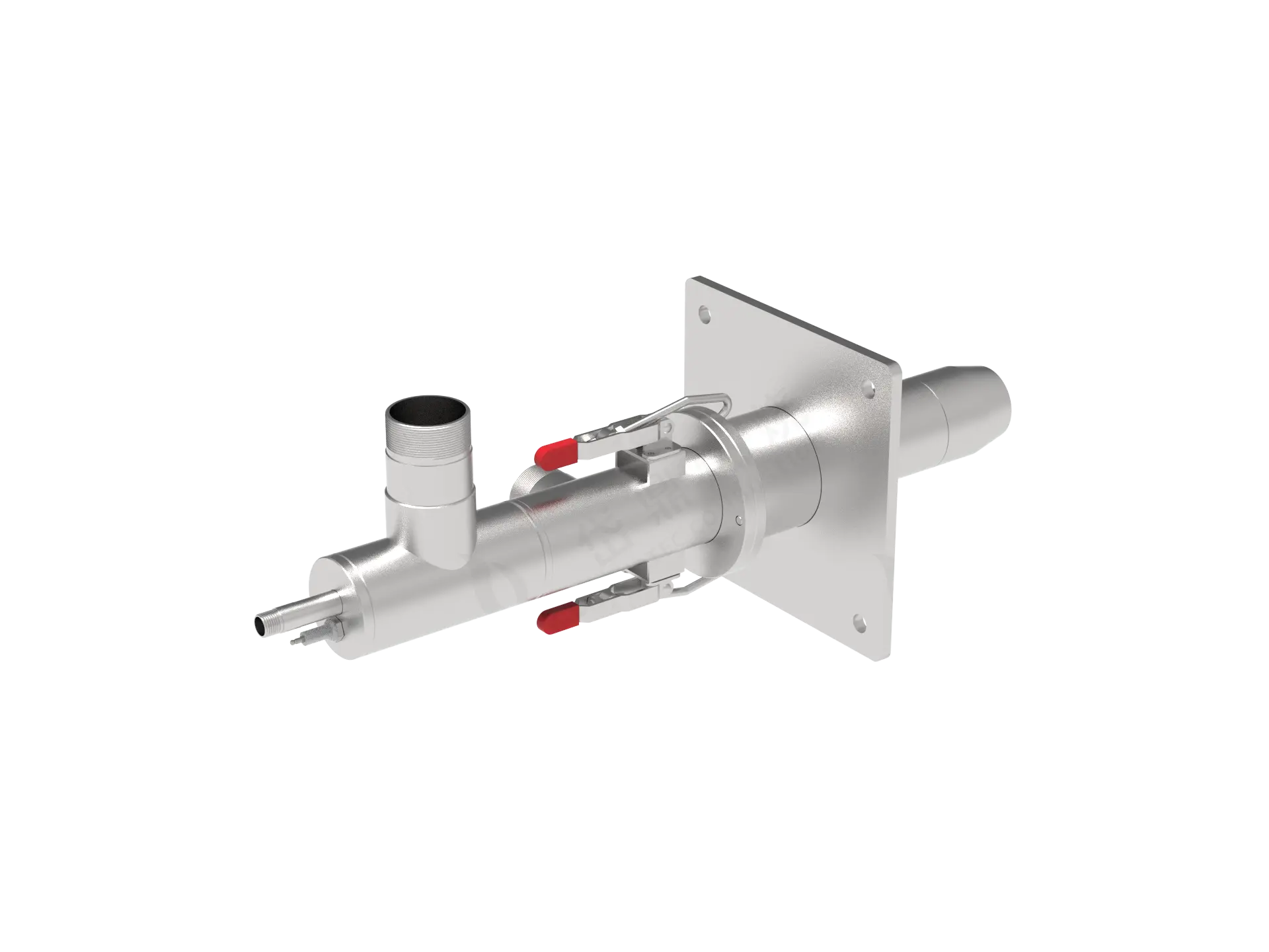
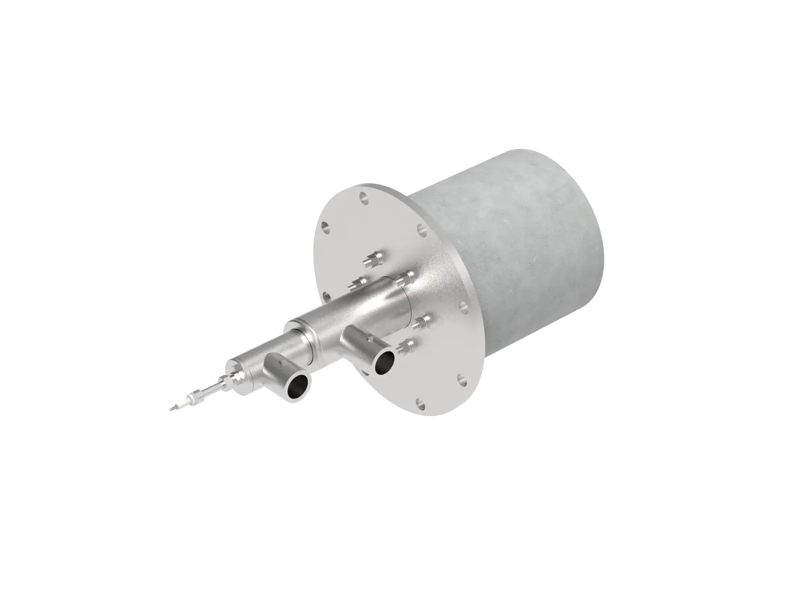
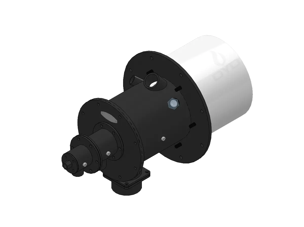
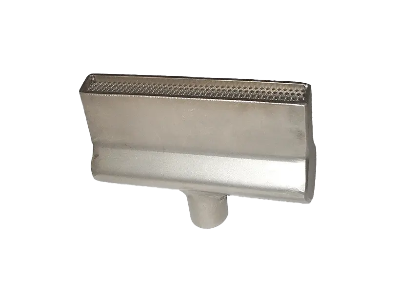
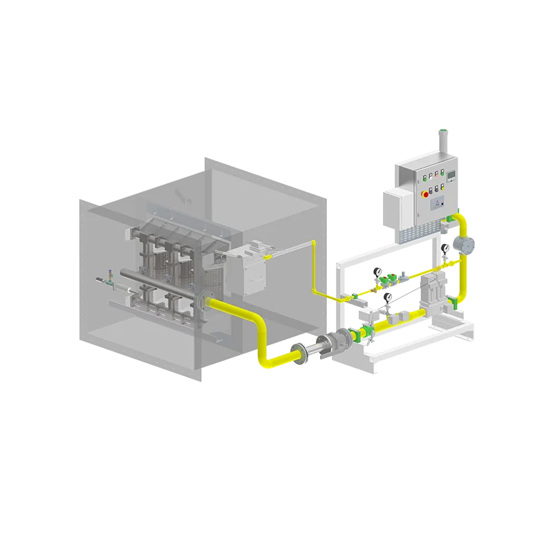
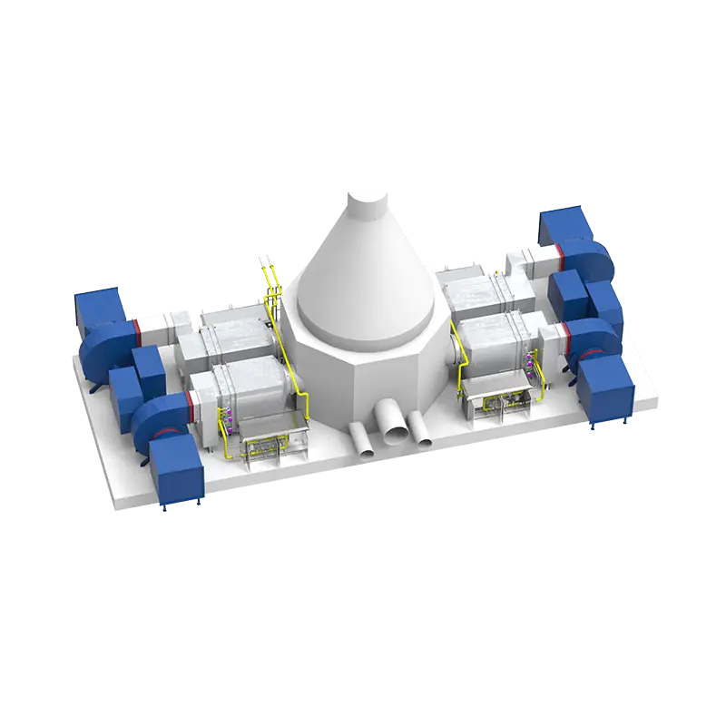
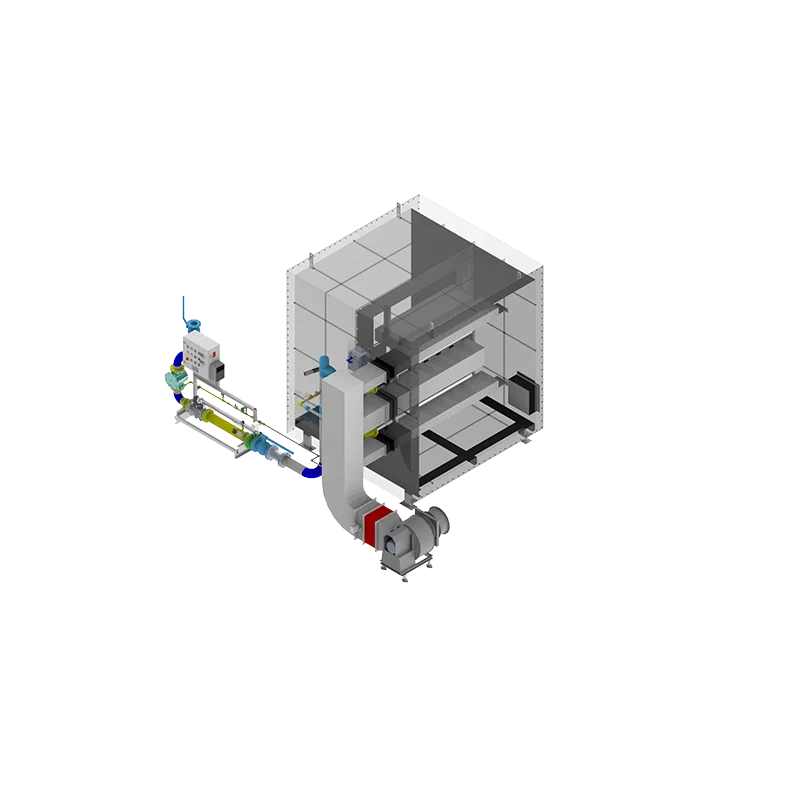
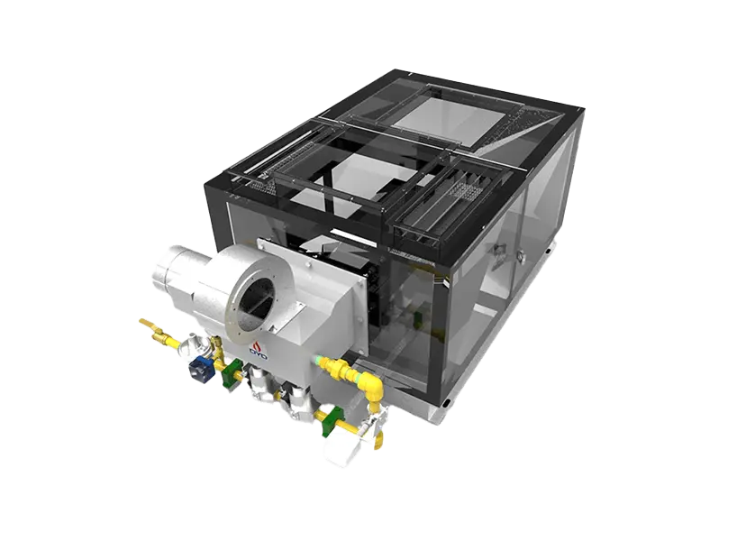
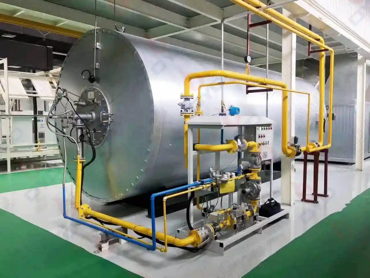
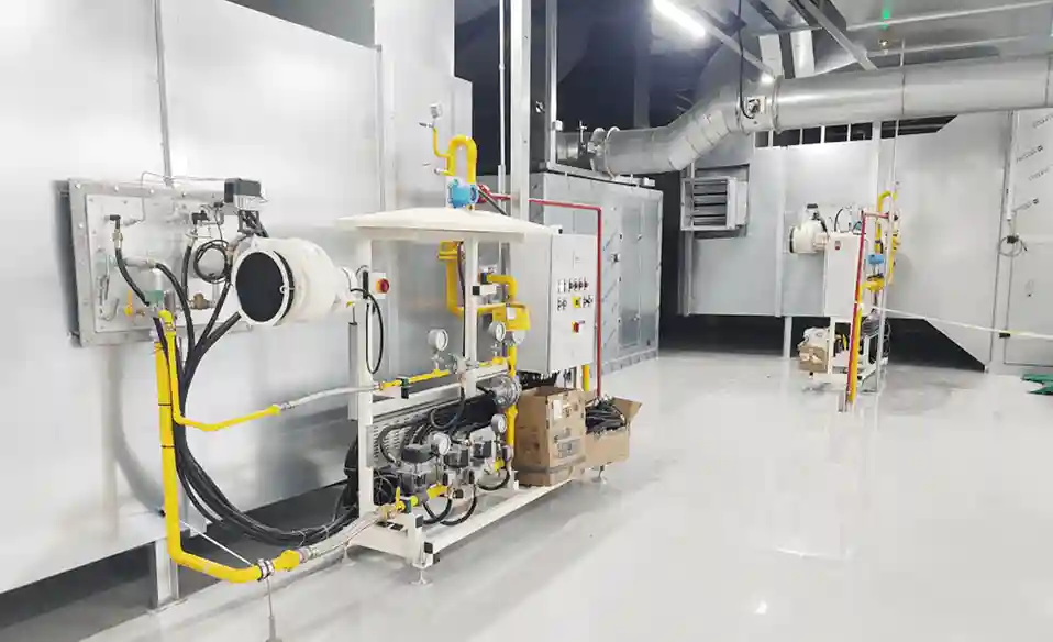
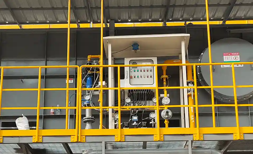
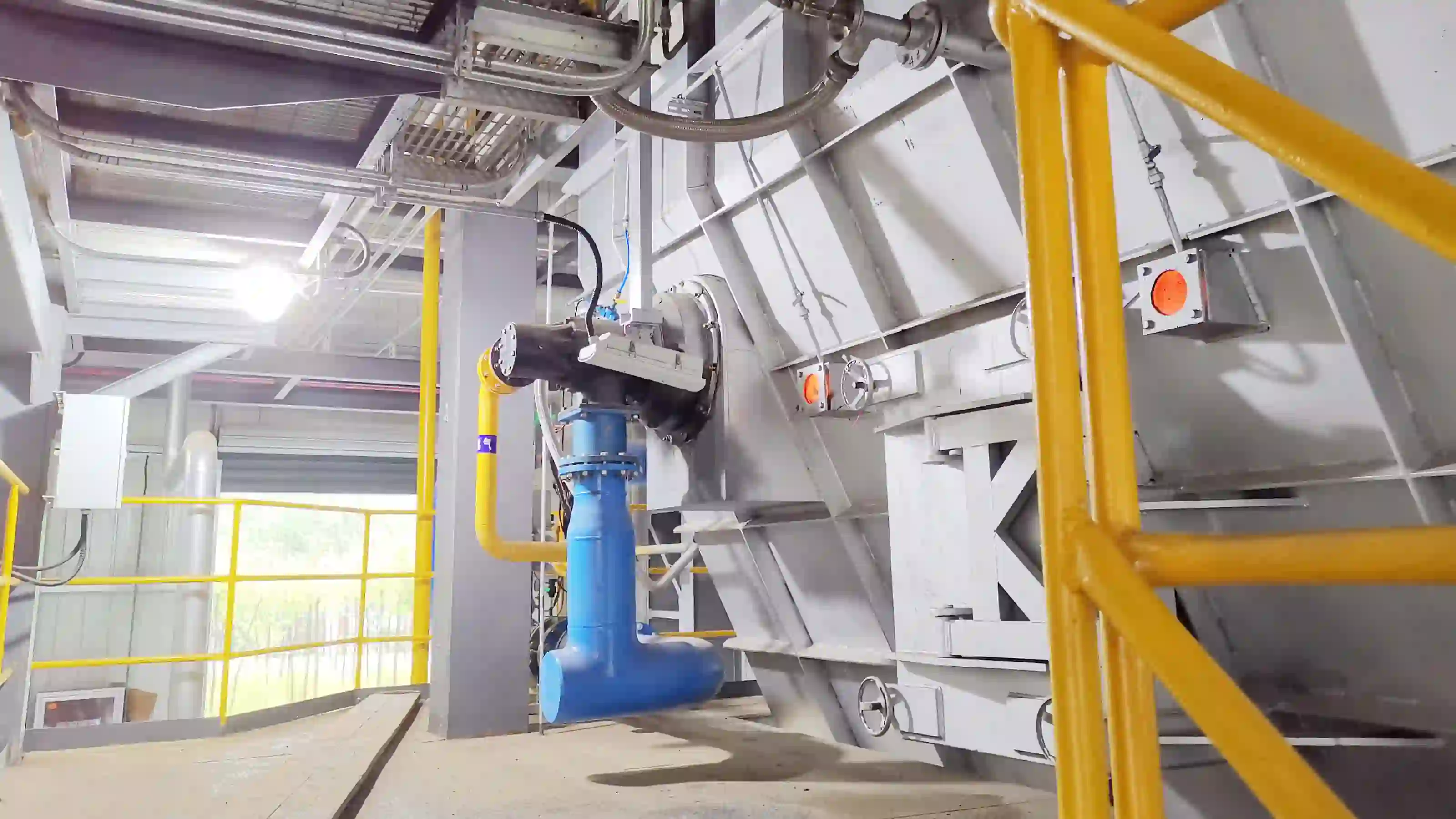
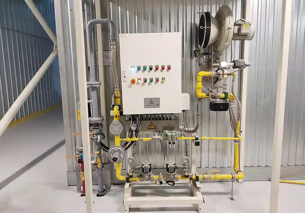
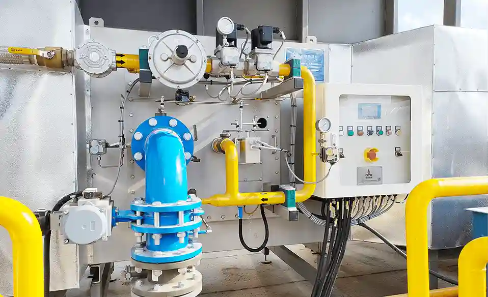
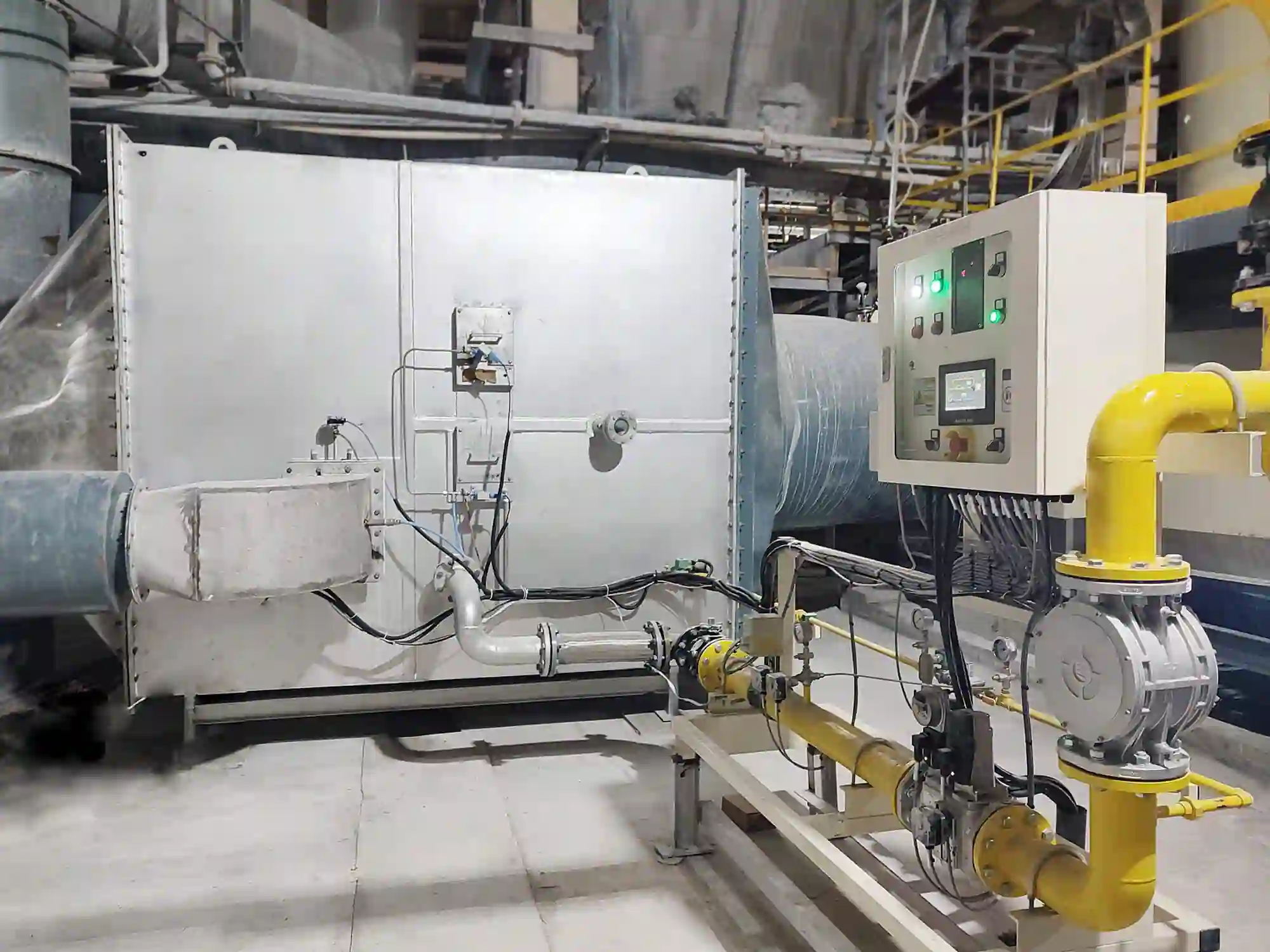
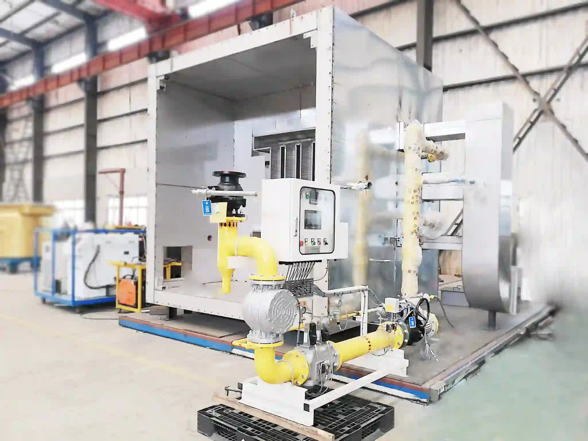
Combustion efficiency is a fundamental factor in the performance of industrial burners, furnaces, kilns, ovens, dryers, thermal air heaters, and other process-heating systems. In an era of rising energy costs, tightening emissions regulations, and increasing competition, achieving high combustion efficiency is no longer a luxury – it is a business necessity. Even small improvements in efficiency can translate into significant annual fuel savings, reduced carbon footprints, and more consistent product quality.
When combustion is properly optimised, more of the fuel's chemical energy is converted into useful thermal energy while maintaining stable flames, appropriate emissions (CO, NOx, and unburned hydrocarbons), and reliable operation over the full turndown range. However, combustion efficiency is not determined by the burner alone. It is the outcome of a complex interplay between multiple subsystems. Fuel pressure, combustion-air supply, air-to-fuel ratio, fuel-air mixing quality, flame stability, excess air levels, furnace pressure, burner load, exhaust conditions, and control strategy can all influence combustion performance. This is why simply increasing the burner capacity or reducing fuel flow does not necessarily improve combustion efficiency – in fact, it can make things worse if other parameters are not adjusted accordingly.
A better approach is to optimise the complete combustion process as an integrated system, using reliable measurements, structured analysis, and targeted adjustments. This article provides a comprehensive guide to the key factors that affect combustion efficiency and practical steps to improve it across a wide range of industrial heating equipment.
Combustion efficiency describes how completely and effectively a fuel is burned. In practical industrial applications, good combustion efficiency generally means:
Fuel is burned as completely as practical (with minimal unburned carbon or hydrocarbons)
Unburned fuel (including CO and volatile organics) is minimised
CO emissions remain within the required range (typically below 50–100 ppm, depending on regulations)
The flame remains stable without flickering, lift-off, or flashback
The fuel-air mixture is properly controlled at all firing rates
Heat is released where it can be effectively transferred to the process (not wasted on walls or through the stack)
Combustion efficiency should be distinguished from overall thermal efficiency. A burner can achieve highly complete combustion – for example, 99% of the fuel's chemical energy is released – while the furnace still wastes a large portion of that energy through excessive exhaust heat, poor insulation, air leakage, or poor heat distribution. In such a case, combustion efficiency is high, but thermal efficiency is low. Therefore:
Combustion efficiency = how effectively fuel is burned (chemical conversion)
while:
Thermal efficiency = how effectively the released heat is converted into useful process heat (including heat transfer and loss minimisation)
Both are important, and in practice, optimising combustion efficiency is a prerequisite for achieving high thermal efficiency, but it is not sufficient by itself. A comprehensive optimisation strategy must address both.
The main factors that influence combustion efficiency in industrial systems include:
Air-to-fuel ratio (the single most influential parameter)
Excess air (how much air beyond stoichiometric)
Fuel-air mixing quality (turbulence, homogeneity)
Fuel pressure (affects flow and injection velocity)
Combustion-air pressure (affects air velocity and mixing)
Burner design (head geometry, swirl, nozzle type)
Flame stability (pilot, stabiliser, recirculation)
Burner load (firing rate as a percentage of capacity)
Furnace pressure (draft, positive or negative)
Furnace geometry (volume, shape, burner placement)
Exhaust conditions (temperature, flow, backpressure)
Control accuracy (sensors, actuators, PID tuning)
Fuel characteristics (composition, calorific value, impurities)
Burner maintenance (cleanliness, wear, calibration)
These factors interact with each other in non-linear ways. Changing one parameter may affect several others. For example, increasing combustion air may improve oxygen availability and reduce CO, but it also increases the mass flow of exhaust gas, which raises the heat loss and may lower the flame temperature. Conversely, reducing air may improve thermal efficiency (by lowering exhaust losses) but can increase CO and cause flame instability if oxygen becomes insufficient. The objective is therefore to find the appropriate operating condition that balances all these effects, rather than trying to maximise one parameter in isolation. This balance is typically achieved through systematic testing and continuous monitoring.
The air-to-fuel ratio is one of the most important combustion parameters. It determines the relative amounts of oxygen and fuel that enter the combustion zone. For natural gas (methane), the stoichiometric (theoretical) air requirement is approximately 9.5 to 10 cubic metres of air per cubic metre of gas, depending on the exact composition. At this ratio, all the fuel would theoretically burn completely with no excess oxygen and no unburned fuel. However, in practice, perfect mixing and ideal conditions are rarely achieved, so some excess air is needed to ensure complete combustion.
If the air supply is too low (i.e., the ratio is below stoichiometric), the combustion zone becomes fuel-rich. This can result in:
Increased CO emissions (a sign of incomplete combustion)
Incomplete combustion (unburned hydrocarbons and soot)
Unburned fuel passing through the system (wasted energy)
Flame instability and potential for flashback or lift-off
Poor temperature distribution due to uneven heat release
Increased fouling from soot deposition on heat-transfer surfaces
If the air supply is excessively high (fuel-lean), combustion may remain complete, but the additional air absorbs a portion of the heat released and carries it away through the exhaust. This lowers the flame temperature and reduces the efficiency of heat transfer to the furnace and product. Therefore, the optimal air-to-fuel ratio is a balance between:
Complete combustion + stable flame + acceptable emissions + minimum unnecessary air
In practice, this means setting the air flow so that the flue-gas oxygen concentration is between 2% and 4% for most natural gas furnaces, with the exact target depending on burner design, furnace type, and process requirements. For example, a furnace with a well-mixed burner may operate at 2–3% O₂, while a furnace with poor mixing might need 4–5% to avoid CO spikes. Using continuous O₂ trim control can automatically adjust the air flow to maintain this target despite variations in fuel quality or ambient conditions.
Excess air is defined as the amount of combustion air supplied beyond the theoretical (stoichiometric) air required for complete combustion. It is usually expressed as a percentage: for example, 20% excess air means 120% of the theoretical air. Some excess air is commonly required in industrial combustion systems to compensate for inevitable variations in fuel composition, air distribution, mixing quality, and operating load. A well-designed burner can operate with as little as 5–15% excess air, while older or poorly maintained systems may run at 50% or more.
However, excessive excess air can significantly reduce overall thermal efficiency. Every kilogram of excess air must be heated from ambient temperature to the furnace temperature (often 800–1200°C in high-temperature applications) and then discharged through the exhaust. The energy required for this heating is supplied by burning extra fuel. The relationship is roughly linear: each 10% reduction in excess air (e.g., from 40% down to 30%) can improve thermal efficiency by about 1–2%, depending on the furnace temperature. Over a year of continuous operation, even a small improvement adds up to substantial fuel savings.
At the same time, reducing excess air too aggressively can increase CO and destabilise the flame. This is especially risky when air flow is uneven or when the burner is near its turndown limit. Therefore, excess air should be optimised using actual combustion measurements (O₂ and CO) rather than by visual flame appearance alone – a blue flame can still have high excess air, and a yellow flame does not always indicate incomplete combustion. The correct approach is to gradually reduce air while monitoring CO; when CO begins to rise above acceptable levels, you have reached the practical minimum excess air for that operating condition.
Efficient combustion depends on how effectively fuel and air are brought together at the molecular level. If fuel and air are poorly mixed, some regions of the flame contain too much fuel (fuel-rich zones) while others contain too much oxygen (lean zones). This unevenness can produce localised temperature spikes, incomplete combustion, and increased pollutant formation. Good mixing ensures that the combustion reaction occurs uniformly throughout the flame volume, releasing heat evenly and minimising both CO and NOx.
Burner-head design directly influences mixing quality. Important parameters include:
Fuel injection velocity (higher velocity improves entrainment of air)
Air velocity (higher air velocity increases turbulence)
Swirl (imparting a rotational motion to the air or fuel stream enhances mixing)
Fuel injection direction (axial, radial, or tangential)
Mixing location (premixed, partially premixed, or diffusion)
Burner-head geometry (shape of nozzles, diffusers, and stabilisers)
Flame stabilisation methods (pilot flame, bluff body, or swirl stabiliser)
Good mixing allows the combustion reaction to occur in a controlled and stable manner, which in turn permits operation with lower excess air. However, maximum mixing intensity is not necessarily the objective – too much mixing can shorten the flame too much, causing high heat release near the burner and potentially overheating the burner block or refractory. The mixing pattern must be designed according to the fuel type, burner type, desired flame characteristics, furnace geometry, and process temperature requirements. In many cases, a staged mixing approach (where some air is introduced later in the flame) can balance mixing quality with temperature distribution and NOx control.
Fuel pressure affects the fuel flow rate and the velocity at which fuel enters the burner. For a given burner nozzle, the flow rate is proportional to the square root of the pressure drop across the nozzle. If the fuel pressure changes significantly from the designed condition – due to regulator drift, filter fouling, or changes in supply pressure – the burner may no longer produce its intended flame characteristics. Fuel-pressure problems can affect:
Fuel flow (too high or too low for the set load)
Mixing (injection velocity affects entrainment of air)
Flame length (higher pressure tends to lengthen the flame)
Flame stability (pressure fluctuations cause flickering)
Burner capacity (maximum and minimum firing rates)
Turndown performance (ability to maintain stable flame at low loads)
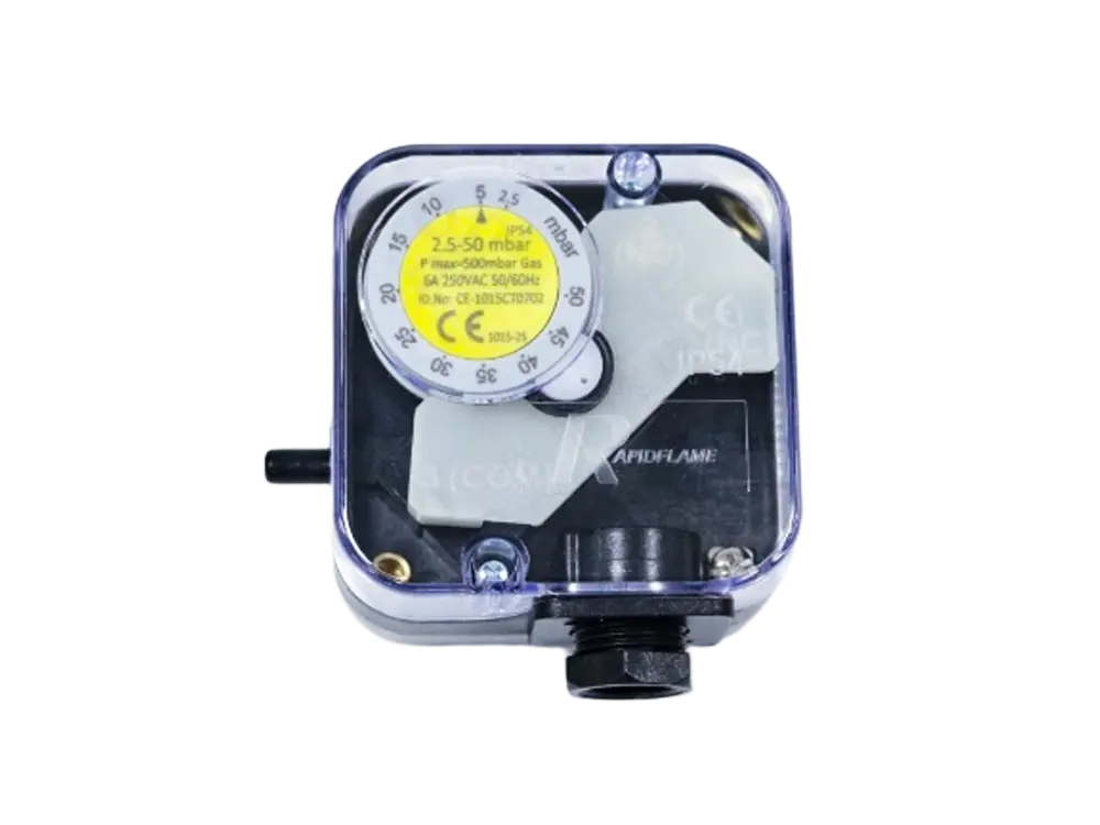
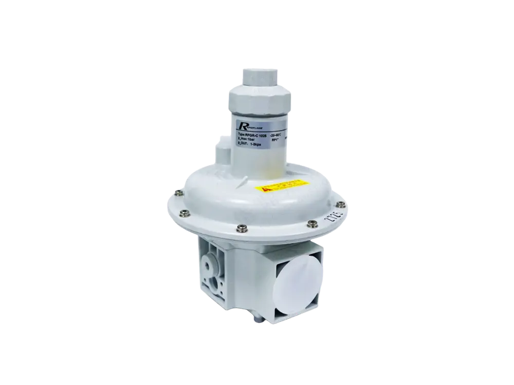
Stable fuel pressure is therefore essential for maintaining consistent combustion. Install a reliable pressure regulator and gauge, and check the pressure regularly – ideally under both static and firing conditions. If the pressure varies by more than ±5% from the setpoint, investigate the cause (e.g., undersized piping, clogged filters, or failing regulator). Also ensure that the fuel supply system is sized to handle the maximum flow without excessive pressure drop, especially during peak demand periods.
The combustion-air system must provide the burner with the required air volume and pressure at all firing rates. This system typically includes a fan (or blower), filters, dampers, ducts, and sometimes a variable-frequency drive (VFD) for speed control. Problems with any of these components can change the actual combustion-air supply, even if the burner's air damper position remains unchanged. Potential symptoms include:
Changing flame shape (longer, shorter, or asymmetric)
Flame instability (flickering, lifting, or pulsating)
Higher CO emissions (due to insufficient air in some zones)
Poor temperature control (fluctuating furnace temperature)
Increased fuel consumption (because the operator compensates by raising the setpoint)
Combustion-air pressure and flow should therefore be monitored as part of burner commissioning and routine maintenance. Use a manometer or pressure transmitter to check the air pressure at the burner inlet, and compare it with the design value. Clean or replace air filters regularly, because a clogged filter reduces air flow and forces the fan to work harder, potentially reducing efficiency. In systems with VFDs, verify that the speed control responds accurately to the air demand signal, and check for hysteresis in dampers and actuators.
Burner capacity should correspond to the actual thermal requirements of the process. An oversized burner – common when designers add large safety margins – may frequently operate at very low load, where combustion stability and efficiency often suffer. At low firing rates, the fuel and air velocities are lower, which can impair mixing and cause flame instability. In addition, the burner may cycle on and off frequently, leading to thermal cycling of the refractory and additional purge losses (cold air drawn through the furnace during pre-purge).
An undersized burner, on the other hand, may operate close to maximum capacity for extended periods, leaving no margin for process variations and increasing the risk of overheating or flame impingement. Both situations make combustion optimisation more difficult. The burner should ideally provide stable combustion across the required operating range, with the normal operating point in the range of 50–80% of maximum capacity. This allows for both peak demands and low-load periods without excessive cycling or instability. When selecting or replacing a burner, use historical load data (or heat balance calculations) to determine the appropriate size, and consider future production changes.
Industrial furnaces rarely require constant maximum heat input. During startup, the burner may operate at high output to bring the furnace up to temperature quickly. Once the furnace approaches its operating temperature, the required heat input may decrease significantly – often to 30–50% of maximum, or even lower during idle or holding periods. A burner with suitable turndown capability can reduce fuel and air input while maintaining stable combustion. This capability is expressed as the turndown ratio (e.g., 10:1 means the burner can operate stably from 100% down to 10% of its maximum capacity).
A high turndown ratio provides better control over:
Fuel consumption (because you can follow the load more precisely)
Furnace temperature (smoother control, less overshoot and undershoot)
Flame stability (no need for on/off cycling)
Process transitions (e.g., ramp-up, soak, and cool-down)
Poor turndown – for example, a ratio of only 3:1 – forces the system to either cycle the burner on and off or operate outside its preferred combustion range. Frequent cycling increases wear on valves and igniters, and the purges between cycles waste heat. Upgrading to a burner with a higher turndown, and matching the air/fuel control system accordingly, can yield significant efficiency gains, especially in batch processes with wide load variations.
The flame should be compatible with the furnace geometry and the heat-transfer requirements of the process. Important characteristics include:
Flame length (the distance from the burner to the flame tip)
Flame diameter (width of the flame envelope)
Flame momentum (the product of mass flow and velocity, affecting penetration)
Flame temperature (peak and average values)
Flame direction (angle relative to furnace walls and product)
Heat-release distribution (where the energy is released along the flame)
A flame that is too long may contact furnace walls or products directly, causing local overheating, refractory spalling, and increased NOx formation. A flame that is too short concentrates heat near the burner, creating a hot zone that may reduce burner life and cause uneven product heating. A flame with excessive momentum may penetrate too deeply into the furnace, increasing the risk of impingement on the far wall. A flame with insufficient momentum may not provide the required circulation of hot gases, leading to stratification and poor uniformity.
The ideal flame is therefore application-specific. For example, a furnace with a long, narrow chamber might benefit from a long, narrow flame to distribute heat along the length, while a wide, shallow furnace might require a flat, broad flame. Burner adjustments – such as swirl settings, gas nozzle position, and air register openings – can be used to tailor the flame shape. In some cases, using multiple burners with different firing angles can help achieve the desired heat pattern. Always test and verify the flame shape under actual operating conditions, using visual inspection (through safety glass) or thermal imaging if available.
Furnace pressure influences both combustion and heat loss. In a typical industrial furnace, the pressure inside the combustion chamber is maintained slightly above or below atmospheric, depending on the design. Excessive negative pressure (draft) can cause ambient air to enter through furnace openings, seals, doors, inspection ports, and material entry/exit points. This infiltration air is cold (20°C) and must be heated to the furnace temperature before it exits through the exhaust. This additional thermal load increases fuel consumption, often by 5–15% in poorly sealed furnaces.
Excessive positive pressure can cause hot furnace gases to escape through the same openings, carrying away heat and potentially creating safety hazards (e.g., flames leaking out). This also wastes energy and may damage nearby equipment. Both conditions reduce thermal efficiency. A properly controlled furnace-pressure condition helps maintain stable airflow through the burner (since the draft affects the air-side pressure) and predictable combustion. Modern systems use a pressure controller with a modulating exhaust damper or a variable-speed induced-draft fan to maintain a setpoint, typically between 0.5 and 2 mmH₂O (slightly positive) to prevent cold-air ingress while minimising hot-gas escape. Regular checks of door seals and gaskets, and replacement when worn, are low-cost measures that pay back quickly.
Combustion efficiency does not guarantee uniform process heating. The flame must transfer its heat effectively to the furnace walls, the load (product), and the internal atmosphere. Poor burner arrangement – for example, placing all burners on one side or using too few burners – can create hot spots (where the flame impinges) and cold zones (where the flame does not reach). Operators often compensate by raising the overall furnace temperature to ensure the cold zones meet the required process temperature, which increases fuel consumption and may overheat the hot zones, leading to quality issues.
To avoid this, consider:
Burner placement (staggered, opposed, or roof-mounted)
Flame angle and direction (aiming to maximise coverage)
Use of high-velocity burners that create recirculation
Installation of baffles or guides to direct hot gases
Zoned firing, where individual zones respond to local temperature measurements
When the furnace has significant temperature variation, improving heat distribution can allow you to reduce the average furnace temperature while still achieving the required product temperature everywhere. This directly reduces fuel consumption and extends refractory life. Computational fluid dynamics (CFD) modelling is often used to design or retrofit burner arrangements for optimal heat distribution.
Combustion produces hot gases that contain the majority of the heat released from the fuel. If these gases leave the furnace at unnecessarily high temperatures – for example, because the furnace is operated hotter than needed or because heat exchange surfaces are fouled – a significant amount of energy is lost up the stack. In high-temperature processes (above 1000°C), exhaust heat losses can account for 30–50% of the total fuel input.
Important parameters that affect exhaust heat loss include:
Exhaust gas temperature (the higher the temperature, the greater the loss)
Exhaust gas flow (the mass or volume flow of gases)
Furnace pressure (affects flow and potential for infiltration)
Excess air (directly increases flow volume)
Air infiltration (adds cold air that must be heated)
Reducing unnecessary excess air and controlling infiltration can lower the exhaust flow. In some cases, the exhaust temperature can be reduced by using a heat exchanger to transfer some of the heat to the combustion air or to another process stream (see section on preheating). Also, ensure that the exhaust duct and stack are properly insulated to minimise heat loss from the gases before they exit. Regular cleaning of heat-transfer surfaces (e.g., radiant tubes or convection sections) prevents fouling, which can increase the exhaust temperature by impeding heat transfer.
Waste heat recovery – specifically, using the hot exhaust gases to preheat the combustion air – is one of the most effective ways to improve overall thermal efficiency. The principle is straightforward:
Hot exhaust gas → heat exchanger (recuperator or regenerator) → preheated combustion air → burner
The burner then receives combustion air that already contains useful thermal energy, typically preheated to 300–600°C or even higher in advanced systems. This reduces the amount of natural gas required to achieve the desired furnace temperature, because the air does not need to be heated from ambient. Fuel savings of 15–25% are common in applications with exhaust temperatures above 500°C and continuous operation.
However, combustion-air preheating also changes the burner operating conditions. Higher air temperature affects flame temperature (which increases, potentially raising NOx), air density (which affects the air flow for a given damper position), burner material limits (some components may not withstand the higher temperatures), and control characteristics (the air/fuel ratio must be compensated for the preheat temperature). Therefore, the burner and heat-recovery system should be designed as an integrated system, with attention to materials, control algorithms, and safety interlocks. In many cases, a recuperative burner that incorporates the heat exchanger directly into the burner body is a convenient and cost-effective solution.
Combustion optimisation should not focus only on complete combustion. Flame temperature and oxygen concentration can influence NOx formation – particularly thermal NOx, which occurs when nitrogen and oxygen react at high temperatures. Very high local flame temperatures (above 1800°C) promote thermal NOx, which is undesirable from an environmental and regulatory perspective.
Low-NOx combustion strategies therefore aim to control the temperature and oxygen distribution within the flame, often by modifying the mixing pattern or using staged combustion. Possible approaches include:
Air staging (introducing only part of the air with the fuel, and the rest later)
Fuel staging (introducing fuel in multiple stages)
Internal flue-gas recirculation (using the burner's momentum to recirculate exhaust gases back into the flame)
External flue-gas recirculation (ducting exhaust gases back to the air inlet)
Premixed combustion (fuel and air are mixed before ignition, promoting a leaner, cooler flame)
Distributed heat release (spreading the combustion over a larger volume to avoid hot spots)
However, excessive dilution or overly aggressive combustion modification can result in increased CO emissions or flame instability. There is often a trade-off between NOx reduction and combustion efficiency. The objective is to achieve a balance that meets regulatory limits for NOx while maintaining acceptable CO levels and good fuel efficiency. This balance depends on the burner design, furnace type, and operating conditions. Many modern low-NOx burners are designed with this balance in mind, and they can achieve both low NOx and high combustion efficiency simultaneously when properly tuned.
Combustion conditions can change as the furnace load changes – for example, during ramp-up, soaking, or cooling periods. An effective control system should respond to these changes promptly and accurately. Depending on the application, combustion control may involve:
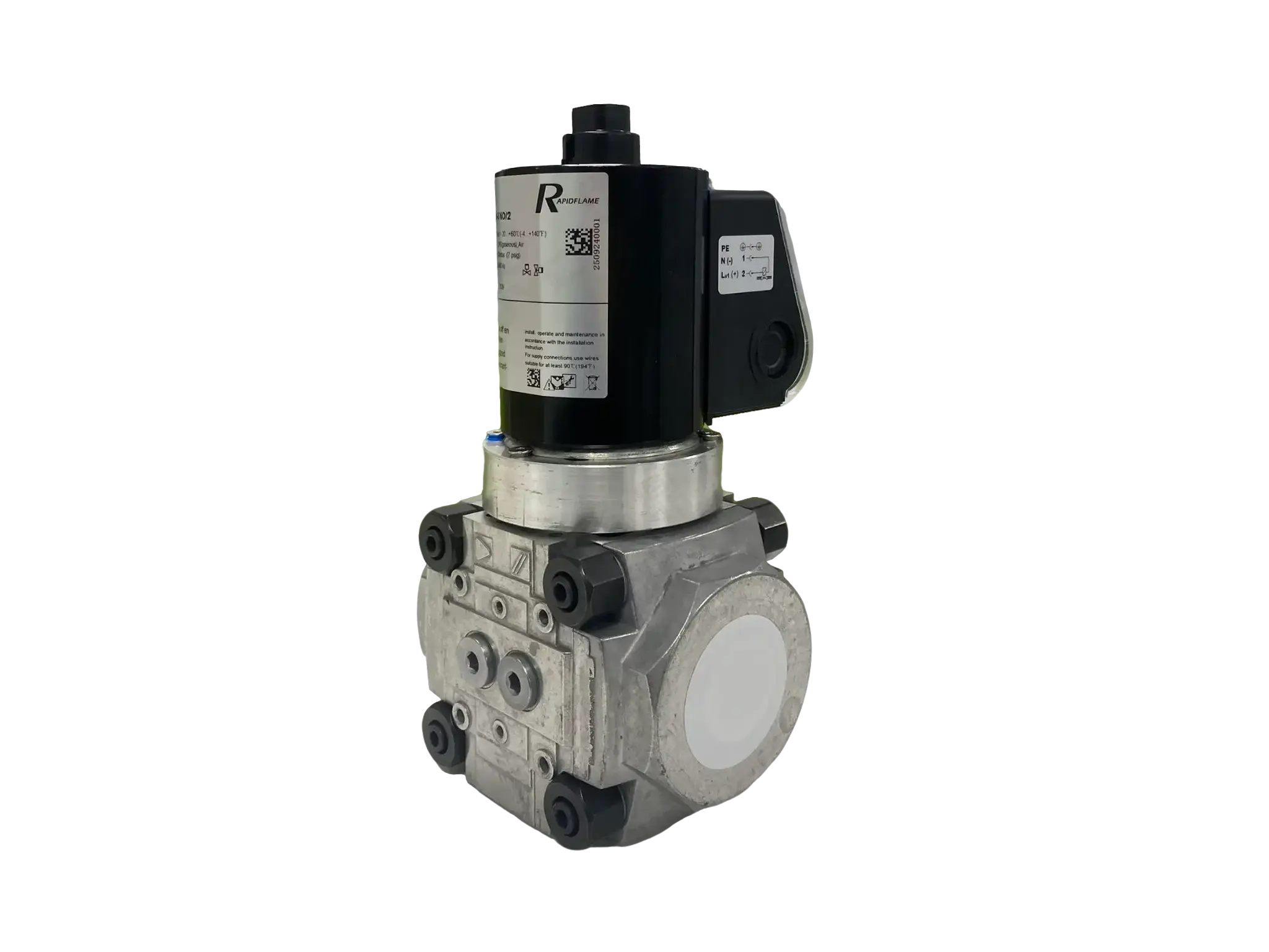
Fuel-flow control (modulating valves or variable-speed pumps)
Combustion-air control (dampers or VFD-driven fans)
Air-fuel ratio control (cross-limiting, parallel positioning, or ratio regulators)
Temperature control (PID loops with appropriate tuning)
Oxygen feedback (closed-loop O₂ trim using flue-gas analysers)
Zone control (independent loops for different furnace zones)
Burner sequencing (for multiple-burner systems)
Accurate control helps keep the burner closer to its intended operating condition, reducing both overshoot and undershoot. It also reduces the operator's tendency to compensate by setting the temperature higher or by running with higher excess air as a safety margin. Using a modern digital control system with high-resolution sensors and fast actuators can improve efficiency by 5–10% compared to manual or older pneumatic controls. Regular calibration of sensors (thermocouples, O₂ analysers, pressure transmitters) is critical to maintain control accuracy.
Flue-gas measurements provide valuable real-time information about combustion conditions. The two most commonly measured species are oxygen (O₂) and carbon monoxide (CO). O₂ concentration indicates the amount of excess air – high O₂ means high excess air, which may be wasteful. CO concentration indicates incomplete combustion – high CO means that some fuel is not being fully oxidised, which is both inefficient and potentially hazardous. For example:
High O₂ + low CO → combustion is complete, but excess air may be higher than necessary, suggesting an opportunity to reduce air.
Low O₂ + high CO → insufficient air or poor mixing; the burner is oxygen-starved in some zones, leading to incomplete combustion.
However, these measurements should always be interpreted together with burner load, fuel composition, furnace pressure, and process requirements. A single measurement cannot fully describe combustion performance. For instance, a high CO spike may occur only at low load due to poor turndown, or only at high load due to fuel pressure drop. Therefore, it is best to install continuous monitoring (not just portable spot checks) and to log the data over time. This allows trend analysis and early detection of degradation. Modern analysers are available as in-situ probes that can withstand high temperatures and provide reliable signals for automatic control.
Burner performance can change over time because of deposits, dust, corrosion, or component wear. In industrial environments, air filters may not capture all particulates, and the fuel may contain trace impurities that lead to nozzle fouling. Over time, the burner head can accumulate carbon (soot) or scale, which alters the intended fuel-air mixing pattern. This can affect:
Flame shape (becoming longer, shorter, or asymmetric)
Flame stability (increasing flicker or causing lift-off)
Combustion completeness (higher CO or unburned hydrocarbons)
Fuel consumption (needing more fuel to achieve the same temperature)
Emissions (increasing NOx or CO)
Regular inspection and maintenance are essential. A good maintenance schedule includes:
Cleaning the burner head, nozzles, and air passages (using appropriate tools and solvents)
Checking and replacing worn gaskets or seals
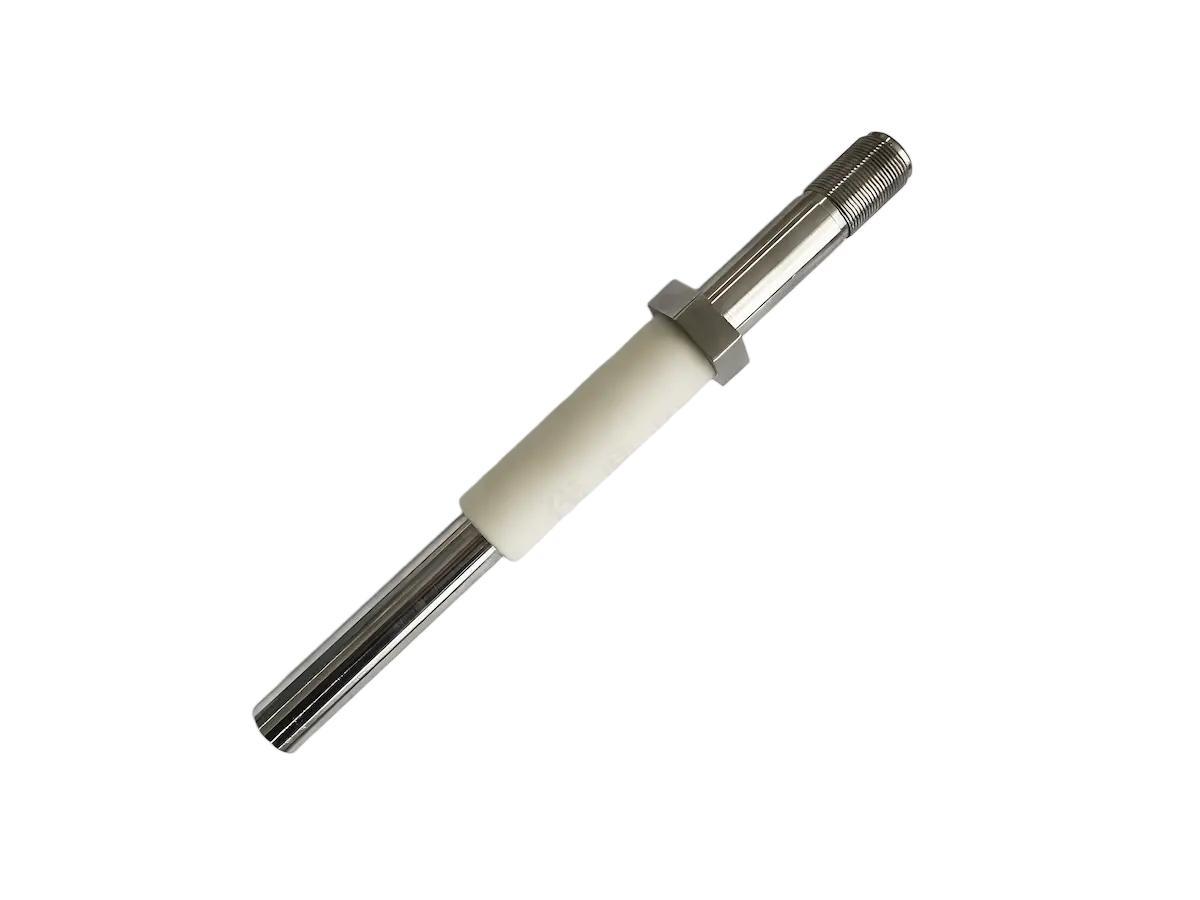
Inspecting the flame stabiliser and ignition electrodes
Verifying the alignment of the burner with the furnace opening
Calibrating pressure gauges and flow meters
Checking for leaks in fuel lines and air ducts
The frequency of maintenance depends on the operating environment – for a dusty application, cleaning may be required monthly, while a clean-room process might need only annual checks. Always follow the manufacturer's recommendations, and keep records of maintenance actions and performance data to detect trends.
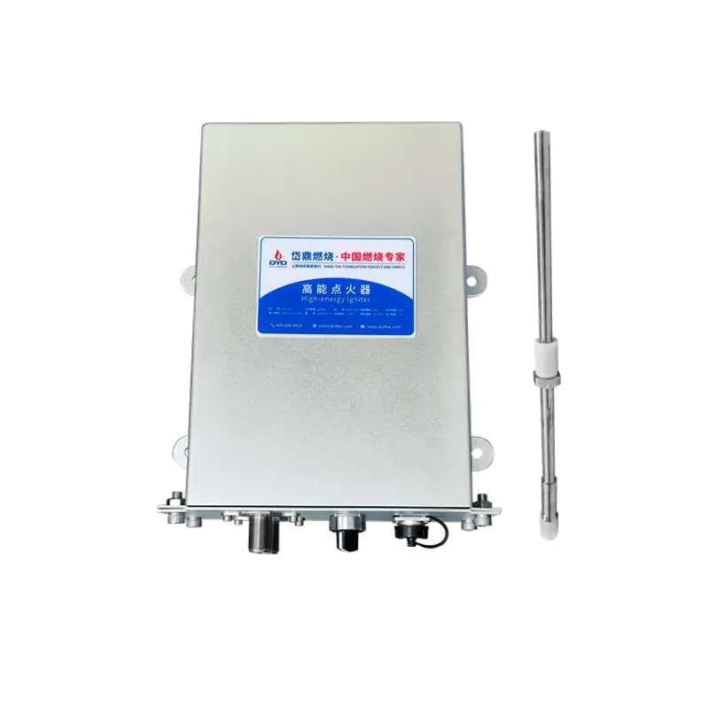
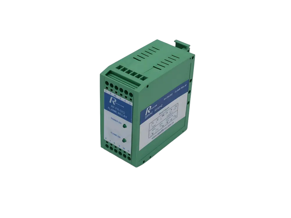
Reliable ignition and flame detection are important parts of a complete combustion system. The ignition system – typically a spark electrode or hot surface igniter – must reliably establish the flame every time the burner is started. A weak spark, fouled electrode, or incorrect gap can cause ignition failures, leading to repeated purge cycles and wasted fuel (and potentially dangerous fuel accumulation).
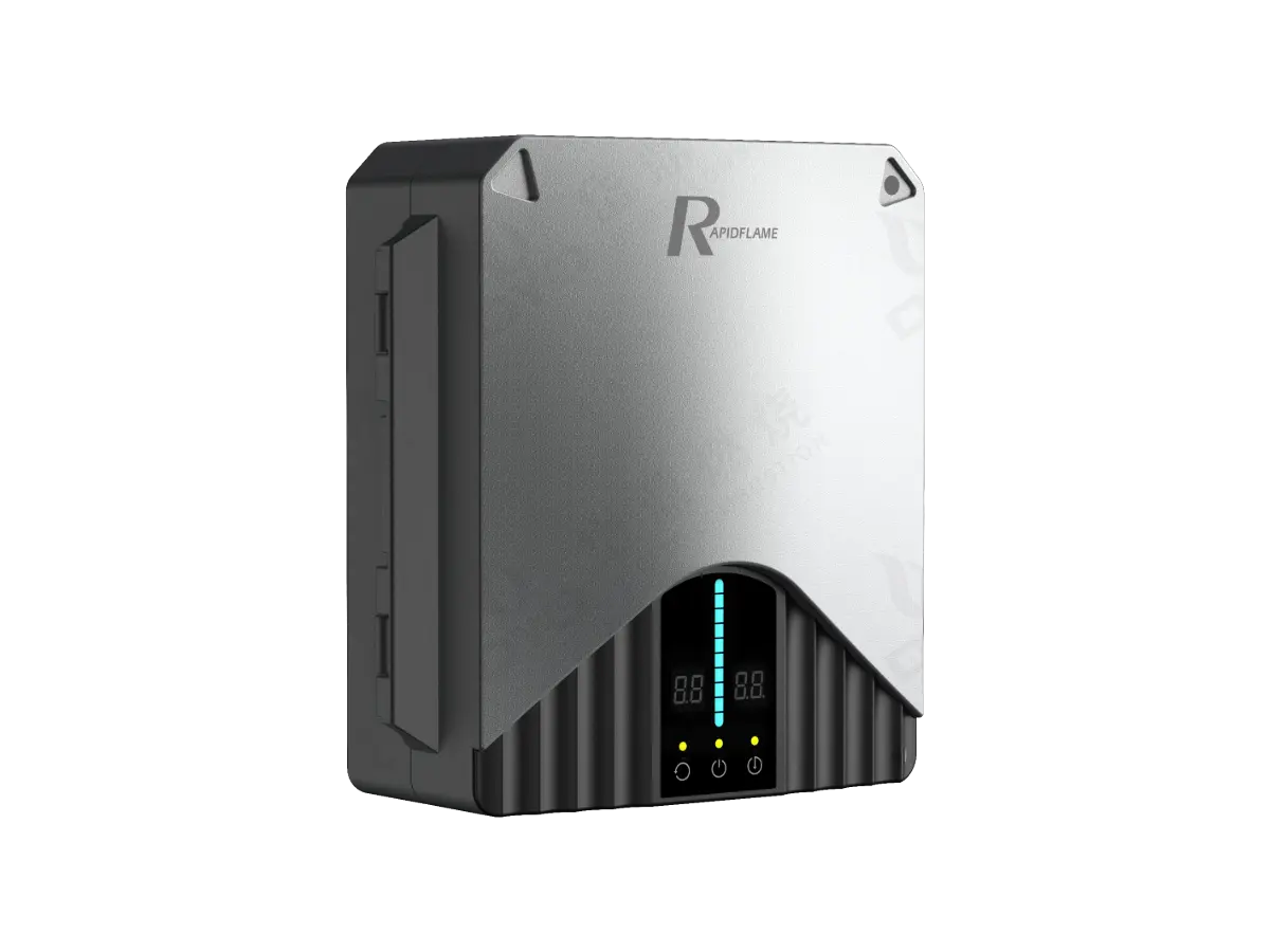
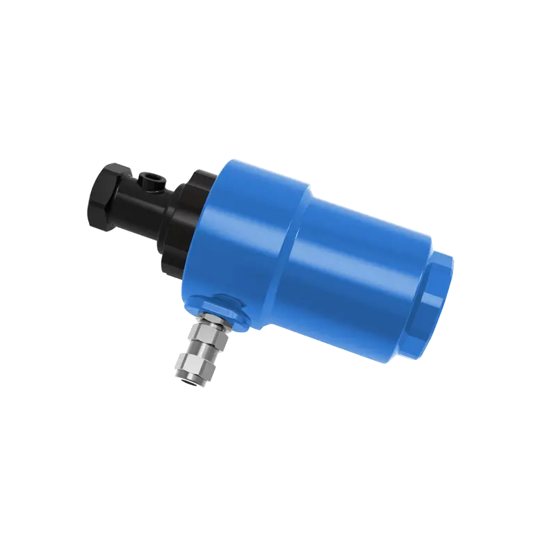
The flame detector – which can be a UV, infrared, or flame rod sensor – must correctly identify the presence of a stable flame and distinguish it from background radiation or reflected light. A contaminated detector lens or a misaligned sensor can cause false flame-out signals, triggering shutdowns even when the flame is actually stable. Unnecessary shutdowns are not only annoying but also waste fuel during the subsequent purges and restarts.
Although ignition and detection systems do not directly determine combustion chemistry, they are essential to reliable burner operation. A burner that fails to start or shuts down unexpectedly cannot be optimised effectively. Regular inspection, cleaning, and testing of these components should be part of the maintenance routine. Also ensure that the safety interlocks (e.g., purge timers, high-pressure cutoffs) are functioning correctly to allow safe operation.
A burner cannot be optimised independently from the furnace. The same burner model can produce completely different combustion results in different furnace chambers, because the available volume, wall configuration, and flow patterns affect how the flame develops and how heat is distributed. Important geometrical factors include:
Furnace volume (total internal space)
Chamber length, width, and height (aspect ratio)
Wall configuration (flat, arched, or circular)
Product arrangement (how the load is positioned and moves)
Burner location (side, roof, floor, or end wall)
Burner angle (tilt, aiming direction)
Exhaust location (affects gas flow and pressure distribution)
For example, a long, narrow furnace may require burners with high momentum to push the flame along the length, while a short, wide furnace may benefit from multiple low-momentum burners to avoid wall impingement. The exhaust position also influences the flame shape – if the exhaust is too close to the burner, it can pull the flame sideways. Therefore, combustion optimisation should begin with a thorough understanding of the furnace geometry. When retrofitting, consider using CFD modelling to predict the effect of burner placement and adjustments before making physical changes. This can save time and money compared to trial-and-error.
A technically complete combustion process is not necessarily the most energy-efficient process overall. Consider two furnaces:
Furnace A achieves excellent combustion (near-zero CO, low excess air) but sends very hot exhaust gas directly to the atmosphere with no heat recovery, has poor insulation, and experiences infiltration. Its combustion efficiency is high, but its thermal efficiency is low.
Furnace B achieves similarly complete combustion but uses appropriate excess air, effective heat transfer, good insulation, and waste-heat recovery to preheat combustion air. Its combustion efficiency may be slightly lower (perhaps due to a trade-off with NOx control), but its overall thermal efficiency is significantly higher.
Furnace B will consume less fuel per unit of production. Therefore, combustion optimisation should ultimately support the overarching process objective:
Convert fuel energy into useful process heat with minimum unnecessary loss.
This means that when optimising, you should not only look at the burner and the flue-gas analysis, but also at the entire thermal system, including insulation, heat exchange, controls, and operating practices. A balanced approach that considers both combustion and heat transfer is the key to achieving the lowest possible fuel consumption.
A practical optimisation process should be systematic and data-driven. It can follow these steps:
Before making any changes, record a comprehensive set of operating parameters. Include:
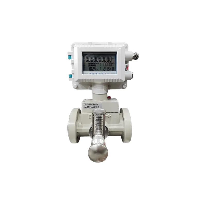
Natural gas consumption (from the meter or flowmeter, preferably per batch or per ton)
Burner load (firing rate as a percentage of maximum)
Fuel pressure (at the burner inlet, under steady operation)
Air pressure (at the burner inlet or fan discharge)
Furnace temperature (average and at key zones)
Exhaust temperature (at the stack or after any heat recovery)
O₂ concentration in the flue gas (wet or dry basis)
CO concentration (ppm)
NOx concentration (if relevant)
Furnace pressure (draft, mmH₂O or Pa)
Production output (to normalise consumption)
Take measurements over at least one full production cycle to capture variations. Record ambient conditions (temperature, humidity) because they affect air density.
Analyse the data to determine the main areas of inefficiency. Is the problem:
Excess air (high O₂)
Incomplete combustion (high CO)
Poor heat distribution (uneven temperatures)
High exhaust losses (high exhaust temperature or flow)
Furnace leakage (infiltration indicated by high O₂ with negative pressure)
Poor control (overshooting, cycling)
Burner deterioration (changes from previous baselines)
Use heat-balance calculations or an energy audit to quantify each loss. This will tell you where to focus your efforts first.
Make controlled, incremental changes to the relevant parameters:
Air-fuel ratio (gradually reduce air until CO starts to rise, then back off slightly)
Burner load (adjust setpoints to operate in the most efficient range)
Flame characteristics (adjust swirl, nozzle position, or damper)
Furnace pressure (tune the exhaust damper or fan speed)
Control parameters (PID gains, setpoints, or oxygen trim settings)
Make only one change at a time, and allow the system to stabilise before taking new measurements. This avoids confusion about which change produced the effect.
Repeat the same measurements as in Step 1 under the same operating conditions (load, production, ambient temperature). Compare the new values with the baseline. Calculate the change in fuel consumption per unit of production.
Fuel savings are not sufficient if the process temperature, production rate, or product quality deteriorates. Evaluate the impact of the changes on:
Production output (tonnes per hour or batch)
Product quality (e.g., hardness, moisture, appearance)
Emissions (CO, NOx – must remain within limits)
Operating stability (flame steadiness, temperature control)
Safety (no increased risk)
If any of these are negatively affected, you may need to adjust further or revert some changes. The final evaluation should consider the overall balance of fuel consumption, production, quality, emissions, and stability. A successful optimisation improves fuel efficiency without compromising other critical factors.
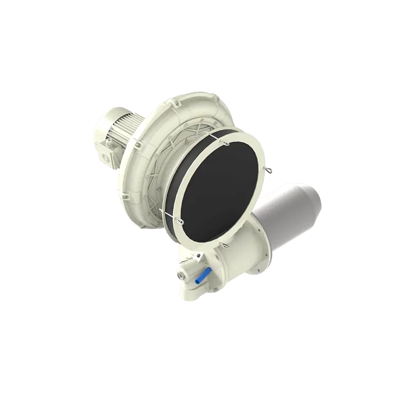
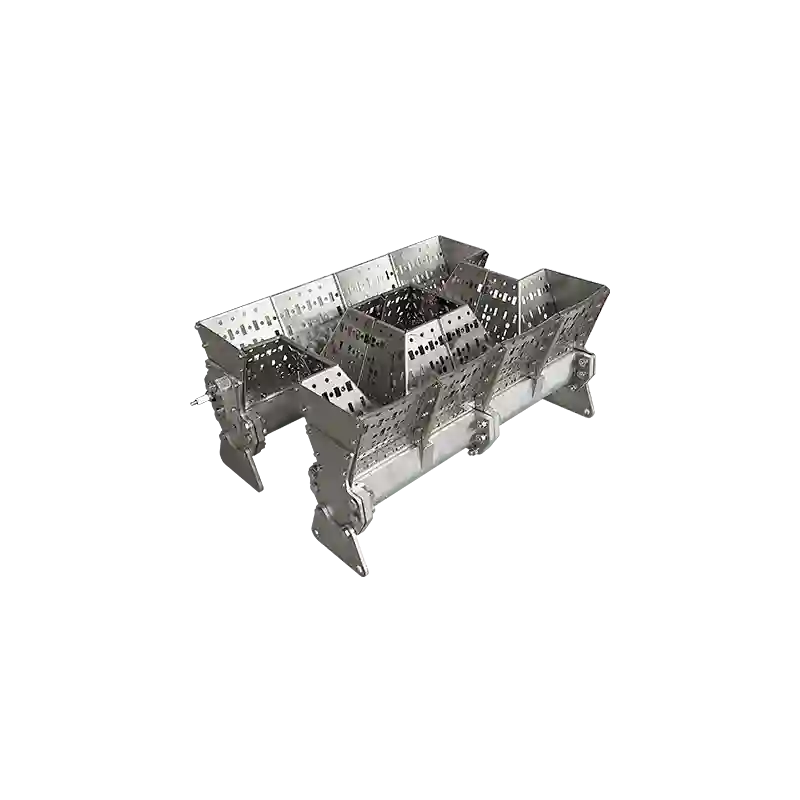
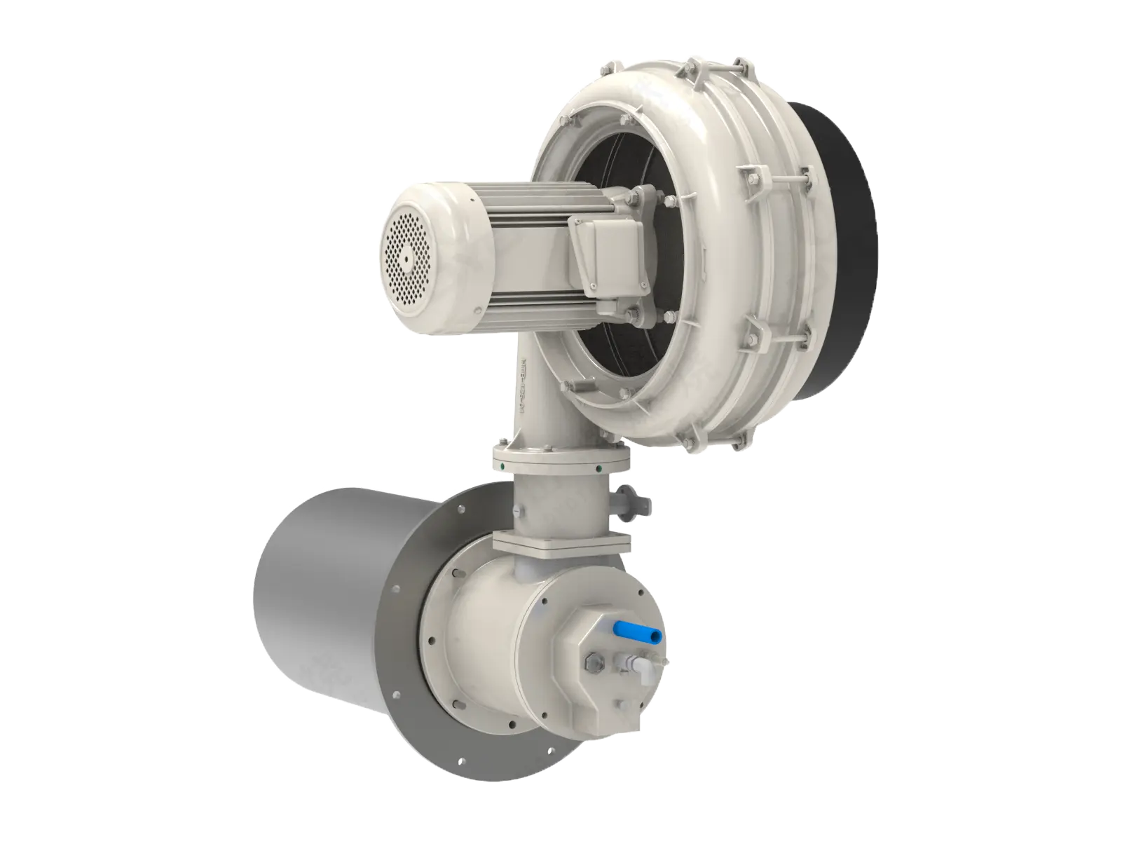
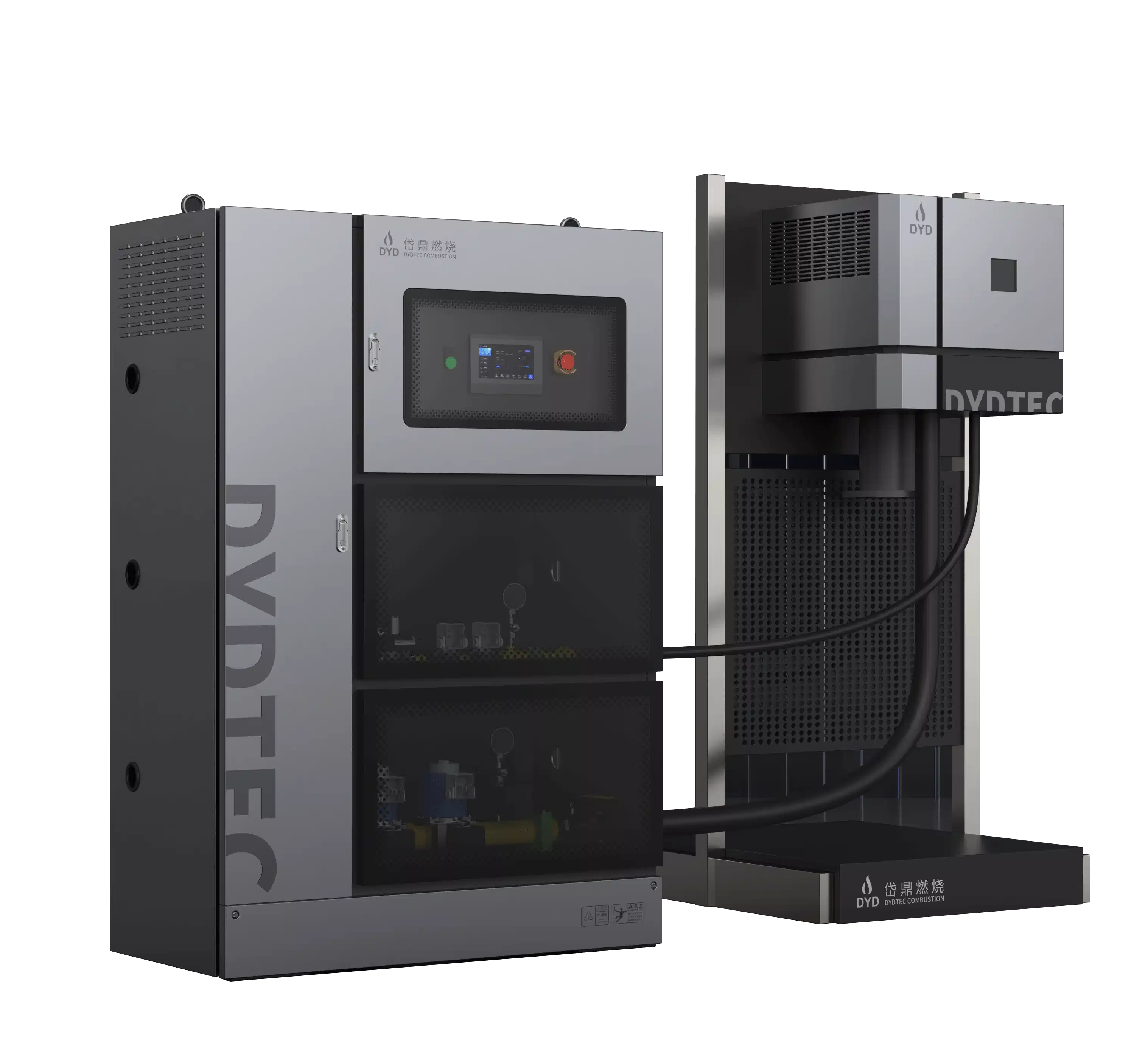
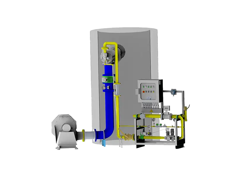
DYDTEC Combustion develops industrial burners, linear burners, thermal air furnaces, and integrated combustion systems for a wide range of industrial heating and thermal-processing applications. With more than 100 burner models and more than 200 application scenarios, DYDTEC Combustion can consider burner selection and combustion optimisation together with heat load, furnace geometry, fuel conditions, flame characteristics, combustion air, control requirements, and process temperature. This integrated approach ensures that the burner and the furnace are designed as a cohesive system, rather than as separate components that are later matched.
The company has production and R&D bases in Shanghai and Yangzhou and serves customers across more than 50 countries and regions. DYDTEC's engineering team provides not only hardware but also application support, including system design, selection, commissioning, and tuning. They understand that combustion optimisation is an ongoing process – conditions change over time, and regular re-optimisation is often needed to maintain peak performance.
For OEM equipment manufacturers, this integrated approach is particularly important because combustion performance is strongly influenced by the relationship between the burner and the equipment. A burner should therefore be selected and optimised together with the furnace, with attention to flame shape, heat distribution, and control integration. DYDTEC's extensive experience across industries – metal heat treatment, ceramics, food processing, chemical reactors, and more – allows them to share best practices and tailor solutions to specific process needs.
There is no single factor that determines combustion efficiency. Air-to-fuel ratio, excess air, fuel-air mixing, burner design, operating load, fuel pressure, and combustion-air conditions all play important roles. However, if one factor were to be singled out, the air-to-fuel ratio (and the associated excess air) is often the most influential because it directly affects both completeness of combustion and exhaust losses. Achieving the right balance is the key.
Not necessarily. More air can provide additional oxygen and help ensure complete combustion, but excessive air increases the mass of gas that must be heated and exhausted, reducing thermal efficiency. The correct air supply is the one that supports stable and complete combustion without unnecessary excess air – typically indicated by 2–4% O₂ in the flue gas for natural gas.
Yes, when the existing system has excessive excess air (e.g., O₂ > 5%). Reducing excess air lowers the exhaust gas flow and thus reduces the sensible heat lost up the stack. However, reducing air too far can increase CO and cause unstable combustion, so it must be done carefully with flue-gas monitoring.
Not by itself. Higher flame temperature does not automatically mean better combustion efficiency. Flame temperature is influenced by many factors, including air preheat, excess air, and burner design. A high flame temperature may indicate efficient combustion, but it can also increase NOx formation and may be associated with high heat release in a small volume. Combustion efficiency is better judged by the completeness of oxidation (low CO) and the overall heat balance.
O₂ provides information about the oxygen remaining in the exhaust, which reflects the amount of excess air. CO can indicate incomplete combustion, which is a direct measure of fuel waste. Together, they provide a powerful diagnostic: high O₂ with low CO suggests room to reduce air; low O₂ with high CO suggests insufficient air or poor mixing; high O₂ with high CO may indicate a severe mixing problem. Using these measurements together, you can fine-tune the air-fuel ratio for minimum excess air without causing CO breakthrough.
A low-NOx burner is primarily designed to reduce NOx formation by controlling flame temperature and oxygen distribution. Depending on its design and operating conditions, it may also provide good combustion performance, but low NOx does not automatically mean higher fuel efficiency. In some cases, low-NOx strategies can reduce efficiency by requiring higher excess air or by diluting the flame. However, modern low-NOx burners are engineered to balance both emissions and efficiency. The key is to select a burner that meets your emissions target without sacrificing too much efficiency, and to tune it properly.
Yes, significantly. Deposits, wear, blocked air passages, damaged burner components, and incorrect settings can change the intended mixing and flame characteristics, leading to higher CO, lower heat transfer, and increased fuel consumption. Regular maintenance is one of the most cost-effective ways to maintain efficiency over time.
Furnace pressure affects air infiltration, exhaust flow, flame behaviour, and heat loss. A negative pressure (draft) can draw cold air into the furnace, increasing the heat load. A positive pressure can push hot gases out, wasting energy. Maintaining an appropriate pressure (usually slightly positive) helps create stable and predictable combustion conditions and minimises these losses. A well-controlled pressure also improves the accuracy of combustion control by keeping the burner air-side pressures stable.
Ideally, combustion should be considered during the furnace design phase. Burner position, flame shape, chamber geometry, exhaust location, and heat load all influence combustion performance. Retrofitting optimisation after the furnace is built is still possible, but some design limitations (like insufficient space for heat exchangers or poor burner placement) may limit the potential improvement. When designing a new furnace, involve combustion specialists early to maximise efficiency opportunities.
It depends on the process and the stability of operating conditions. For continuous, stable processes, an annual re-optimisation may be sufficient, supplemented by regular monitoring of O₂ and CO to detect drift. For batch processes with wide variations, or for systems with variable fuel quality, more frequent checks (e.g., quarterly) are advisable. Also re-optimise whenever you change fuel, replace major components (burner, fan, controls), or alter the furnace operation (e.g., new product type). A good practice is to establish a baseline and then use trend charts to trigger re-optimisation when deviations exceed a set threshold.
Optimising combustion efficiency requires more than adjusting a burner flame by eye. It demands a systematic, measurement-based approach that considers the interaction of multiple factors across the entire thermal system. The most effective strategy is to control the complete combustion process:
Correct burner selection → Stable fuel supply → Controlled combustion air → Optimised air-to-fuel ratio → Effective fuel-air mixing → Stable flame → Uniform heat release → Controlled furnace pressure → Efficient heat transfer → Minimum unnecessary exhaust loss
The objective is not simply to burn fuel faster or produce a hotter flame. The objective is to convert fuel energy into useful process heat as efficiently, consistently, and safely as possible. This means balancing completeness of combustion with minimisation of heat losses, and also considering emissions, product quality, and operational stability.
For industrial furnaces, kilns, ovens, dryers, and OEM thermal equipment, combustion efficiency is ultimately a system-level result created by the interaction of the burner, furnace, fuel system, air system, exhaust system, and control system. Improvements often come from addressing the largest loss mechanism first – whether that is excess air, poor mixing, heat loss, or control inaccuracy. With careful measurement, targeted adjustments, and regular maintenance, most industrial combustion systems can achieve significant fuel savings, often in the range of 5–20%, while also reducing emissions and improving process reliability. In a world where energy costs and environmental concerns continue to rise, combustion optimisation is not just a technical exercise – it is a strategic imperative.