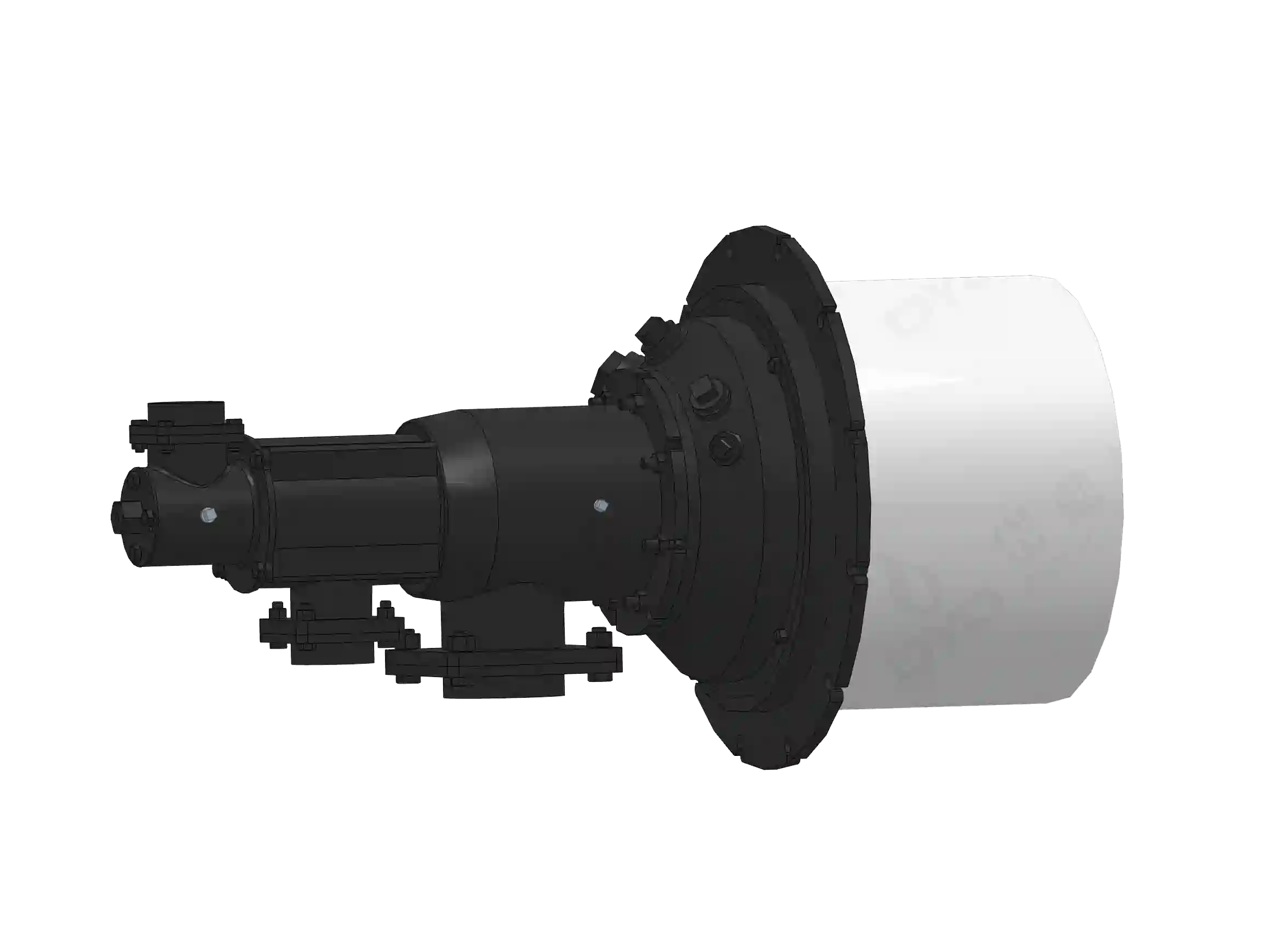
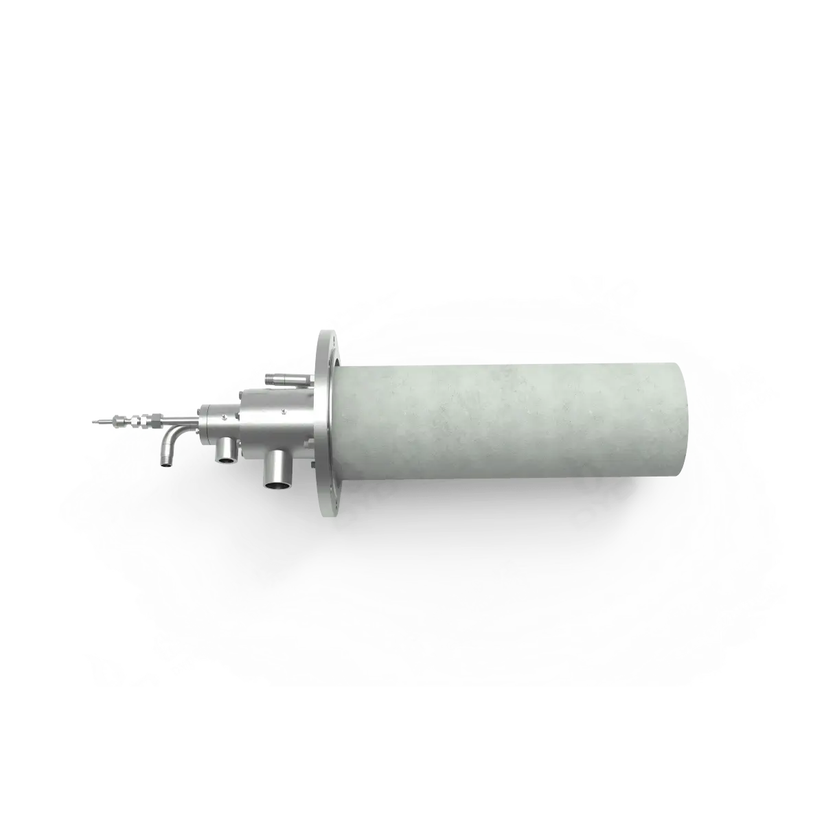
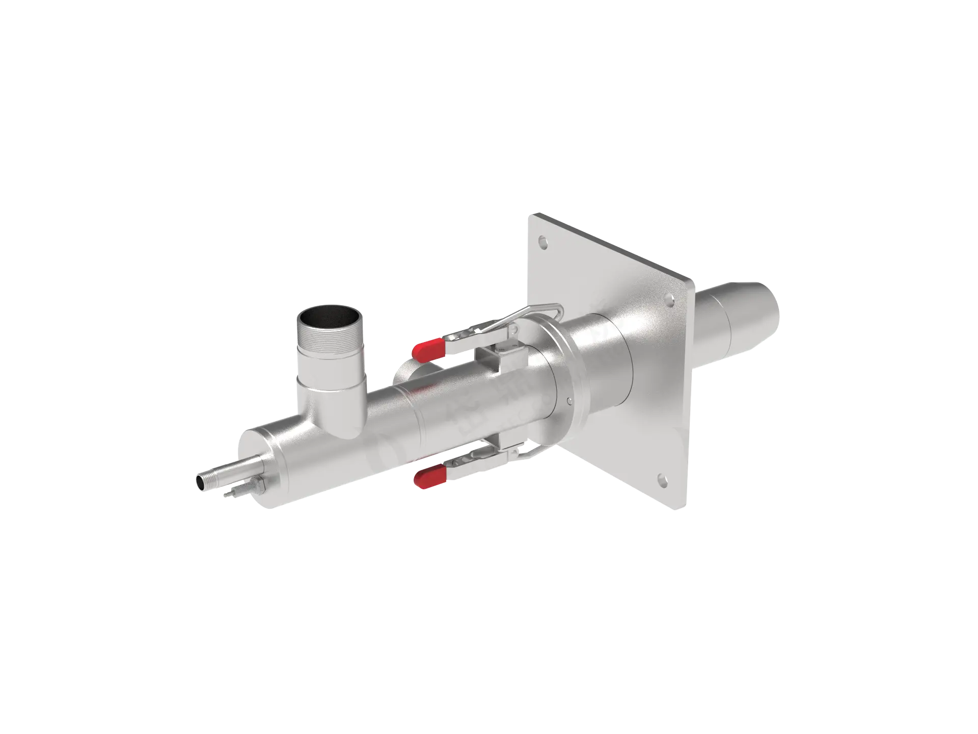
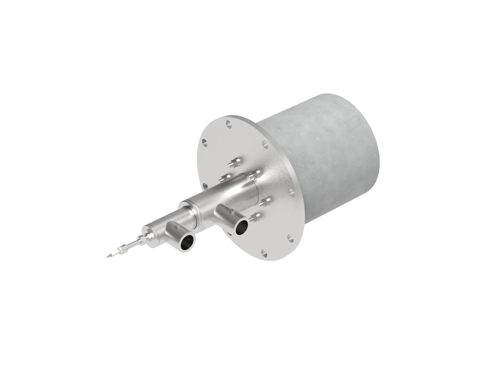
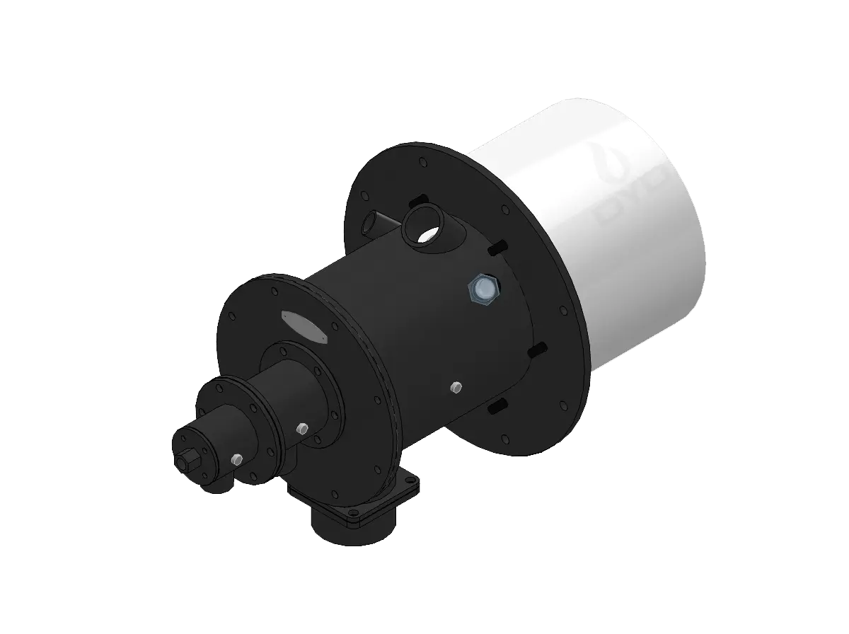
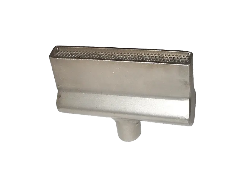
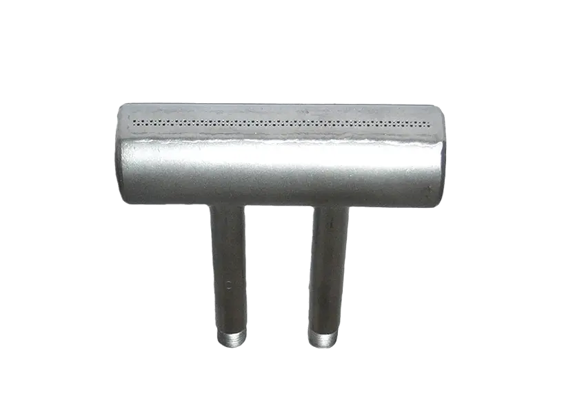
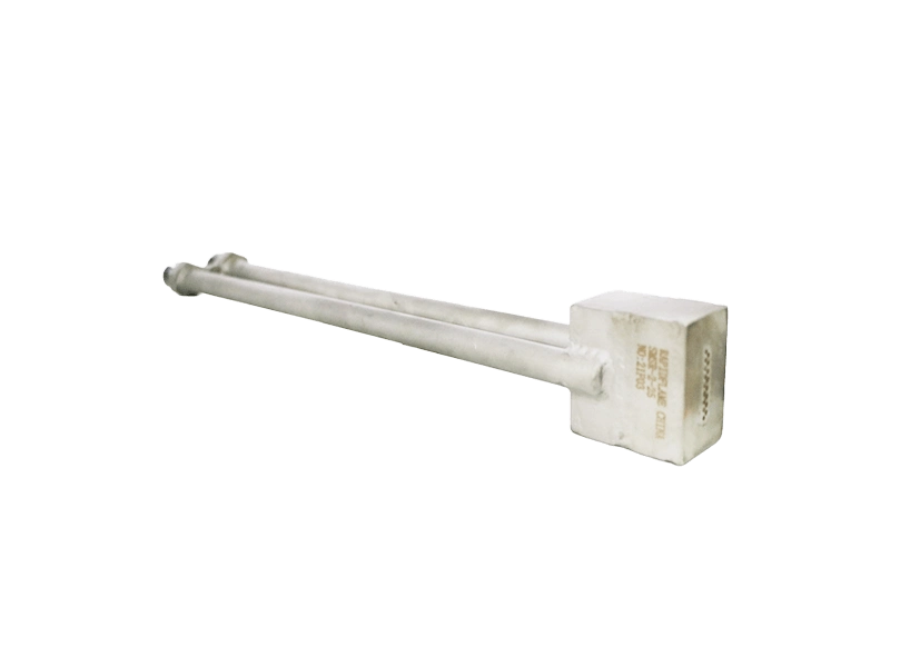
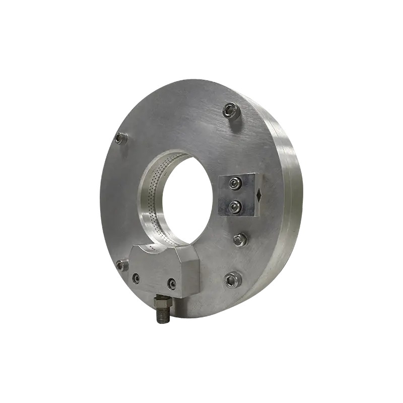
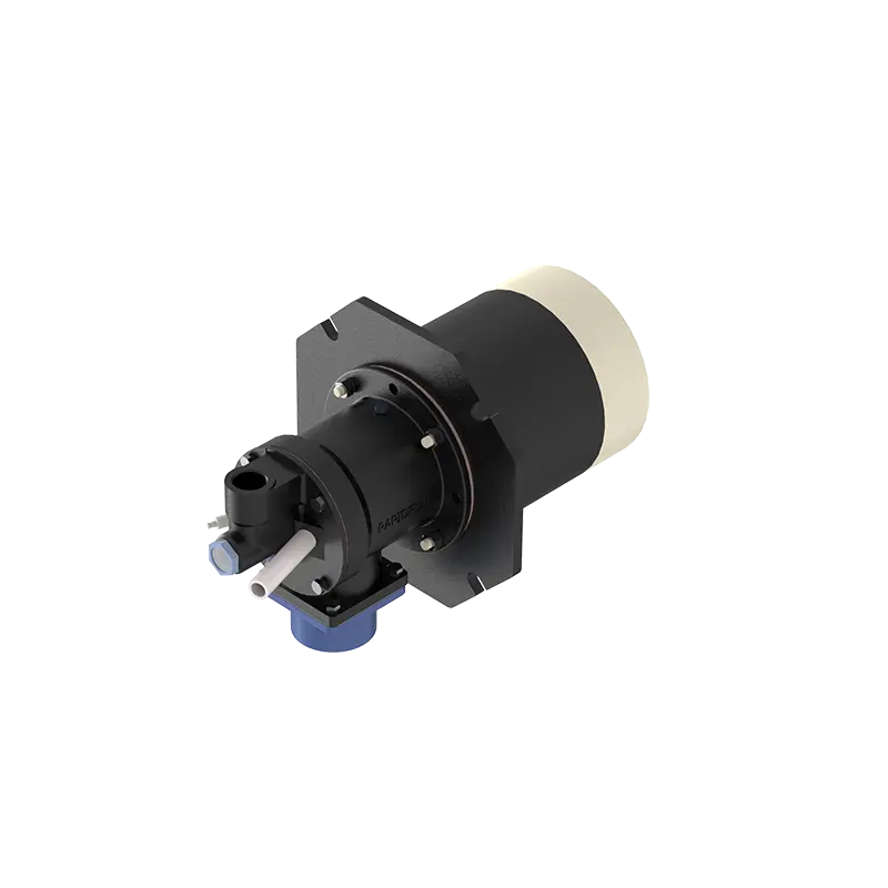
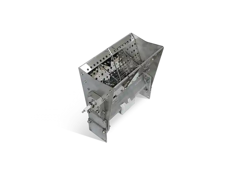
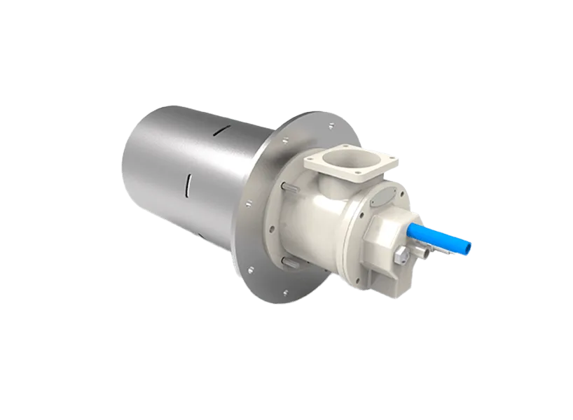
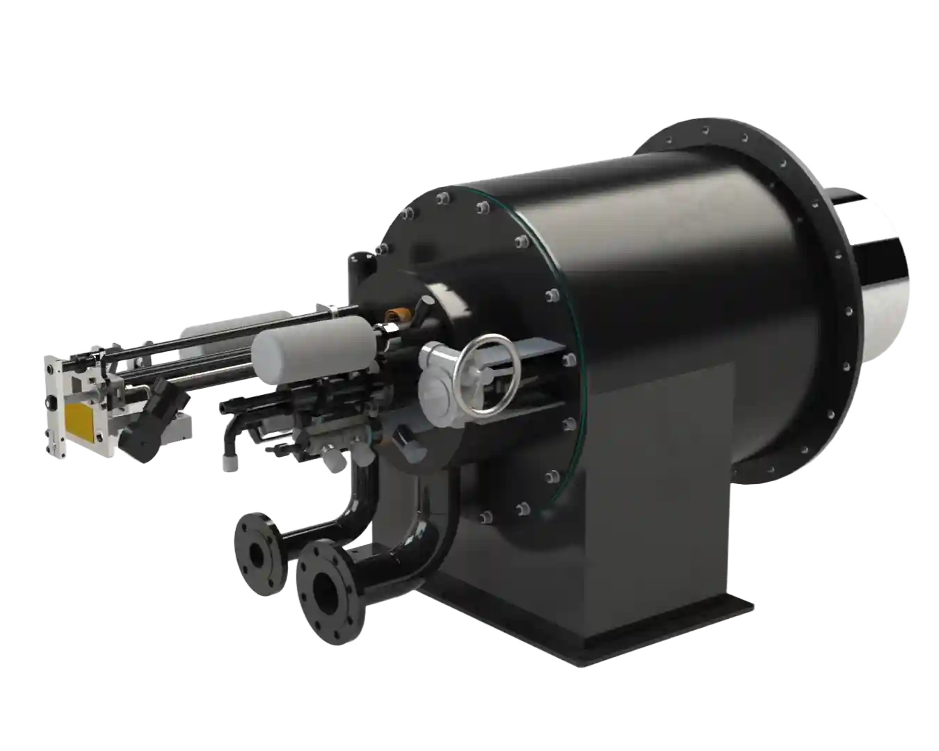
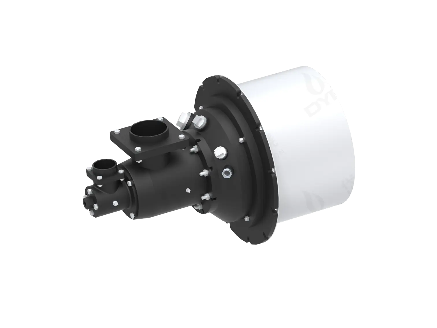
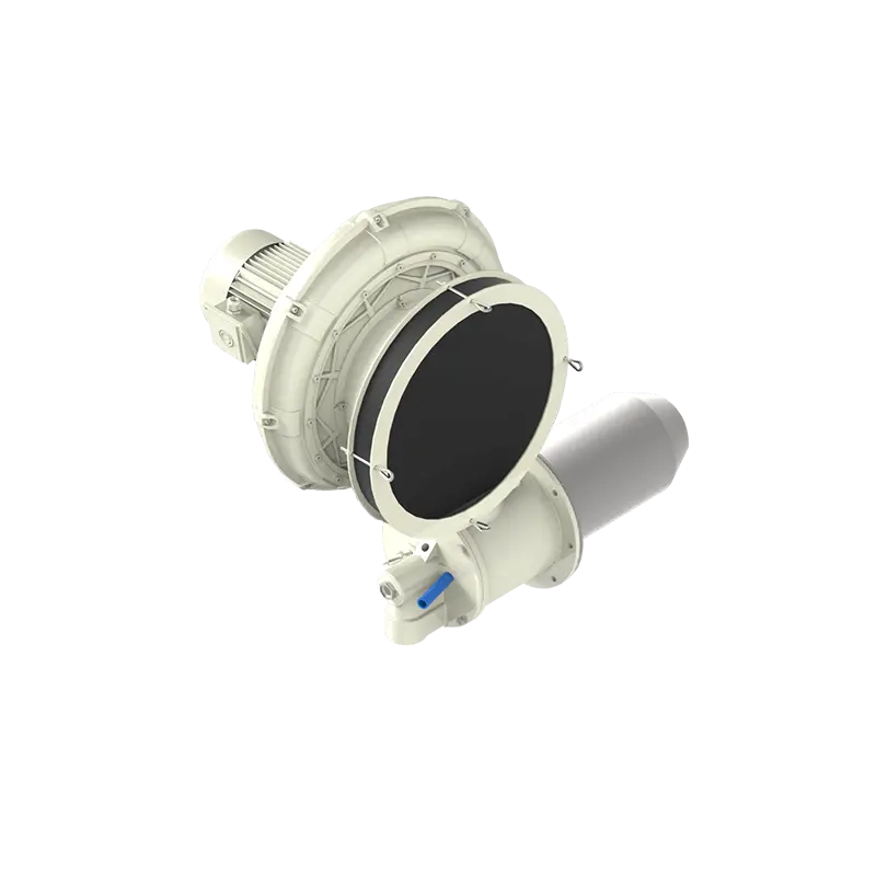
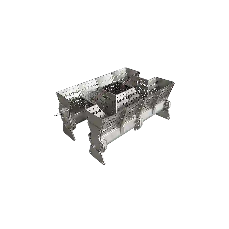
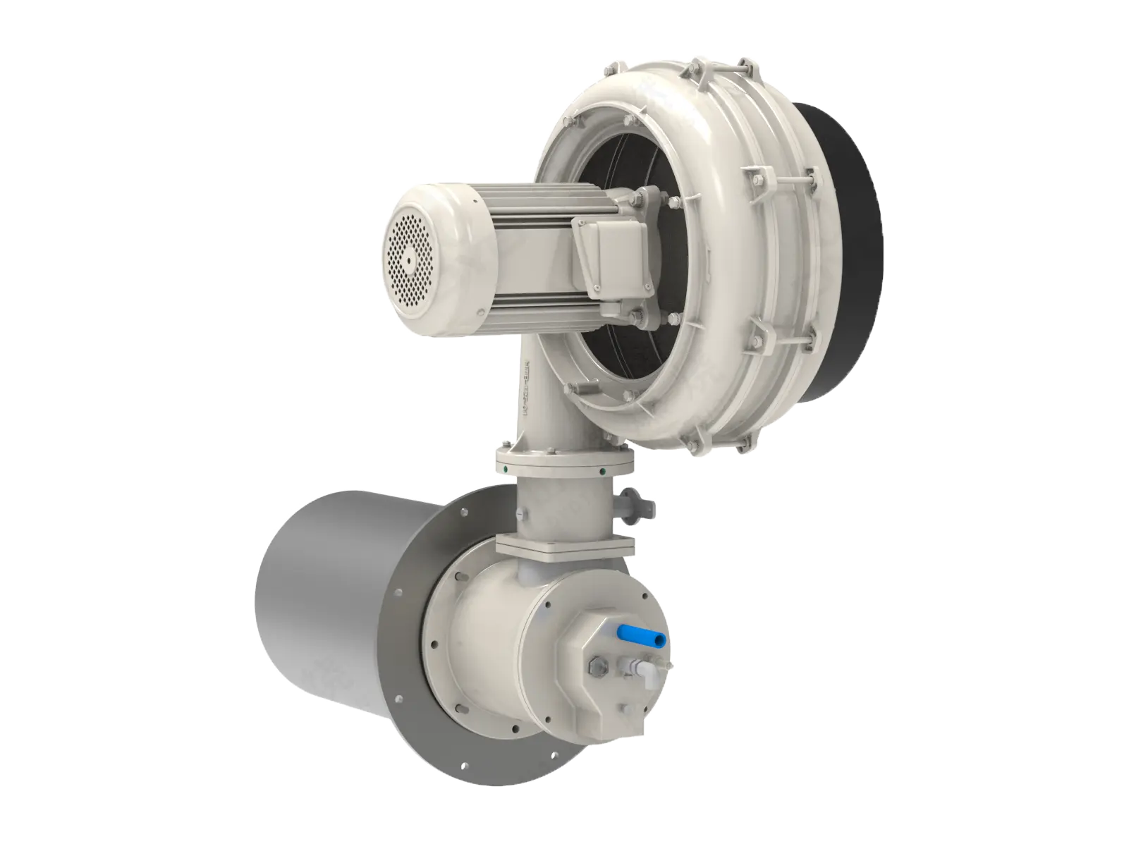
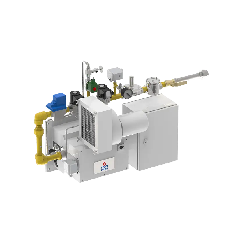
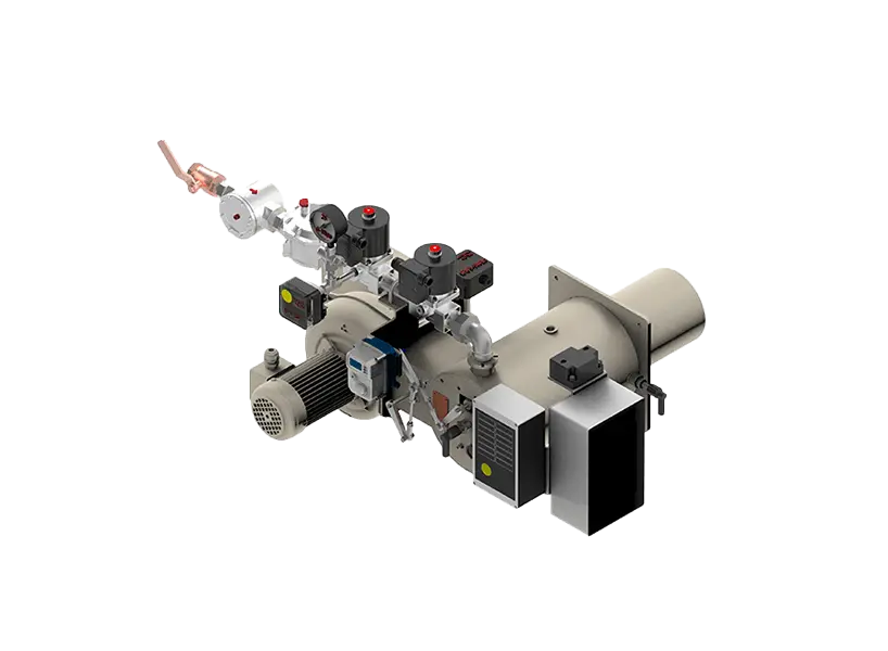
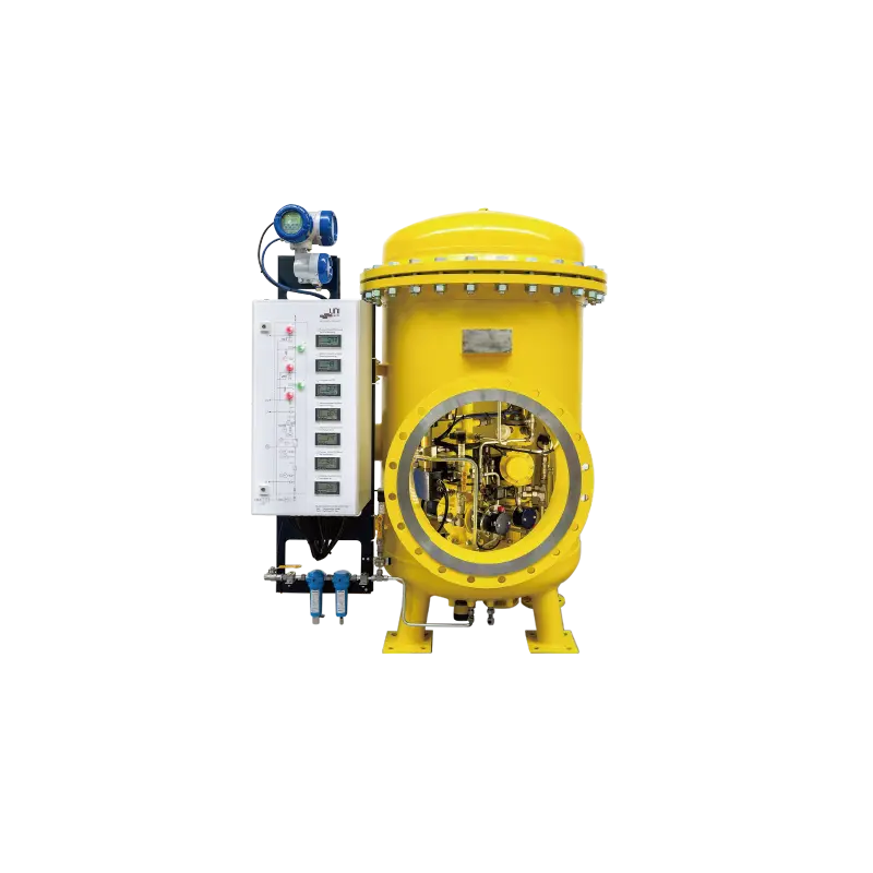
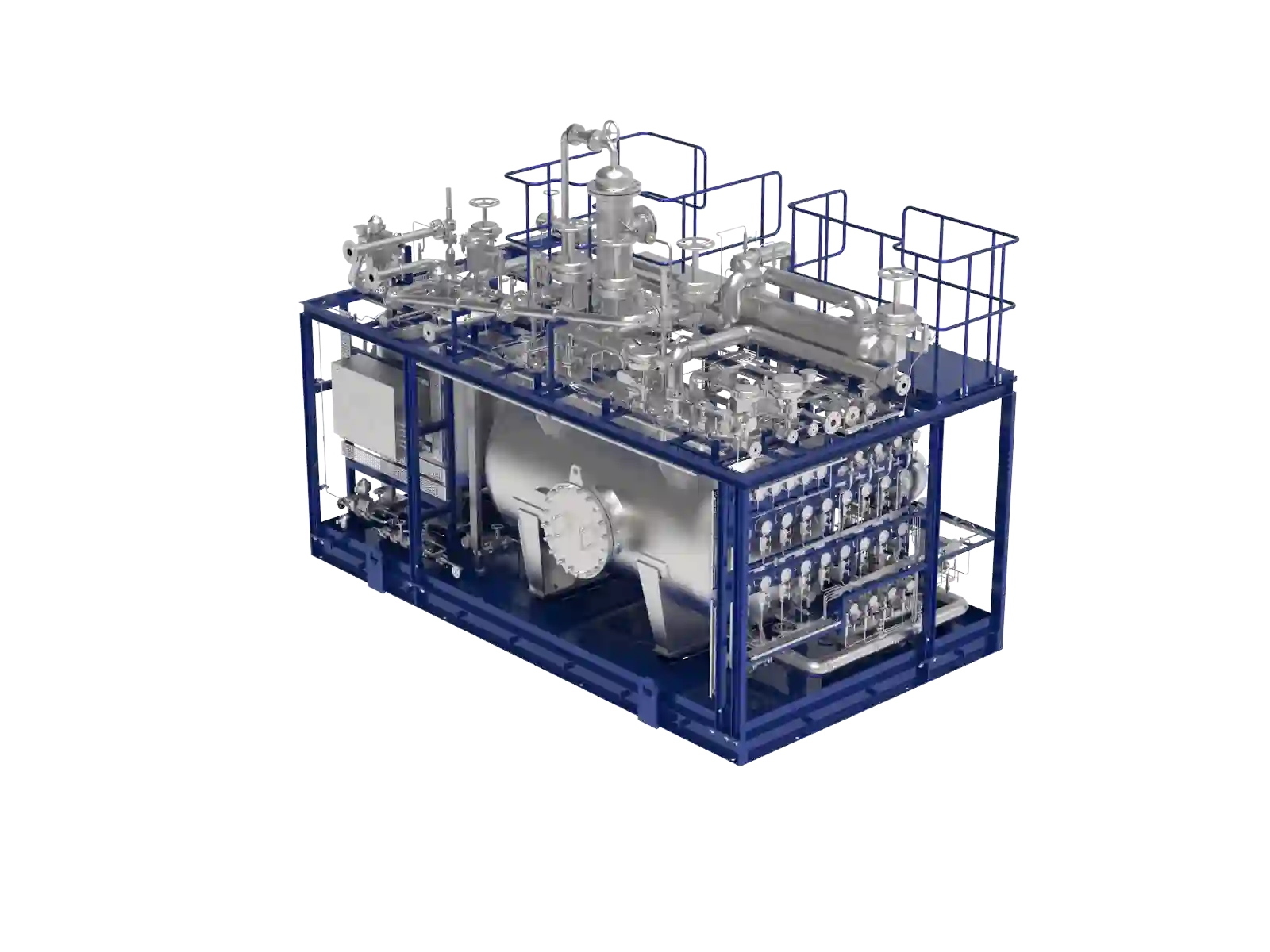
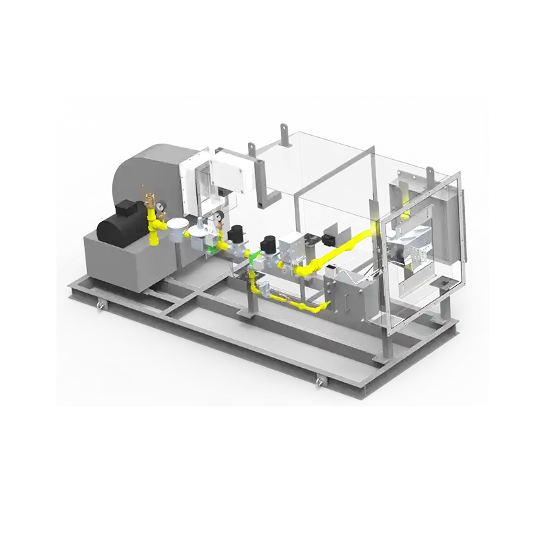
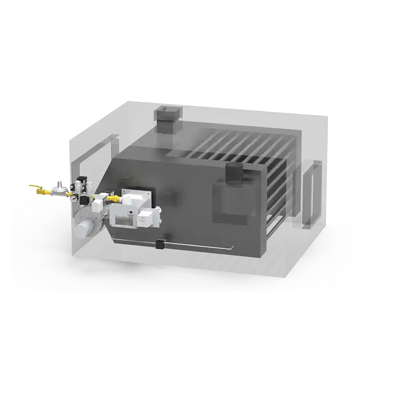
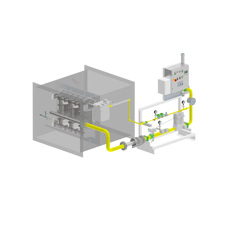
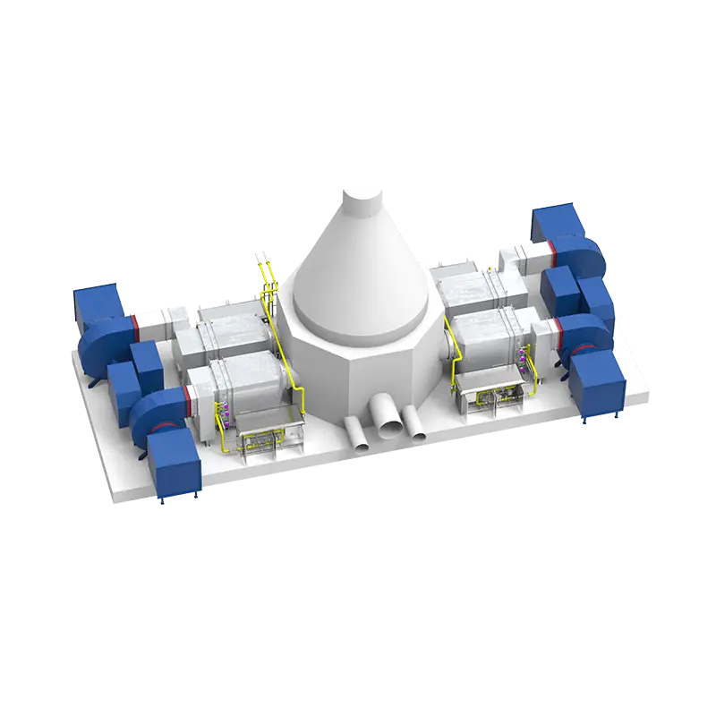
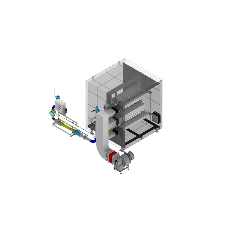
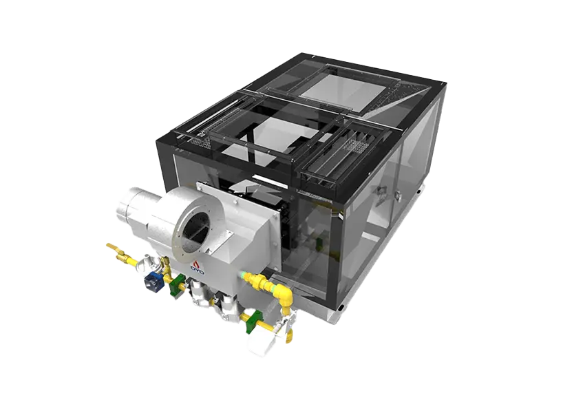
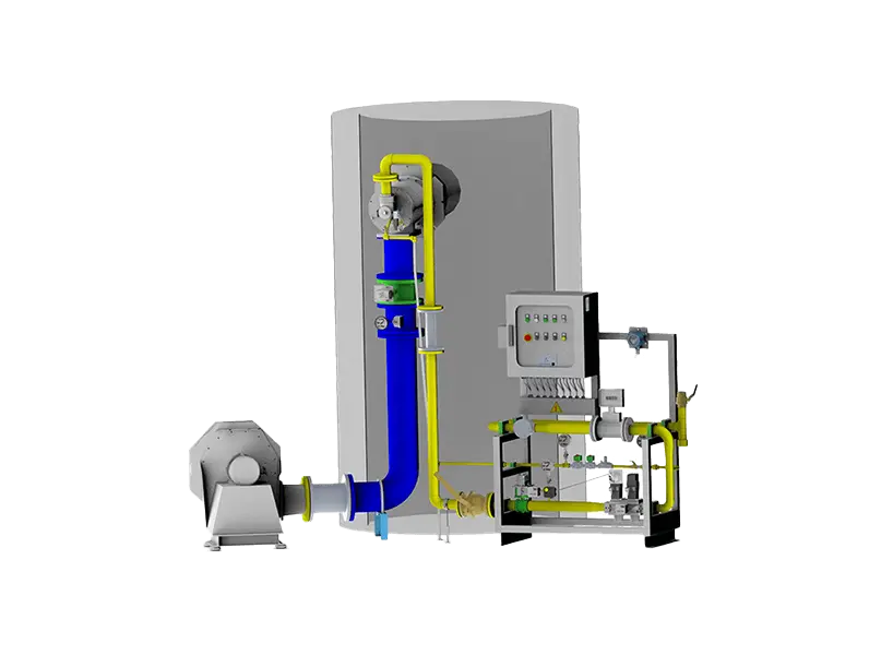
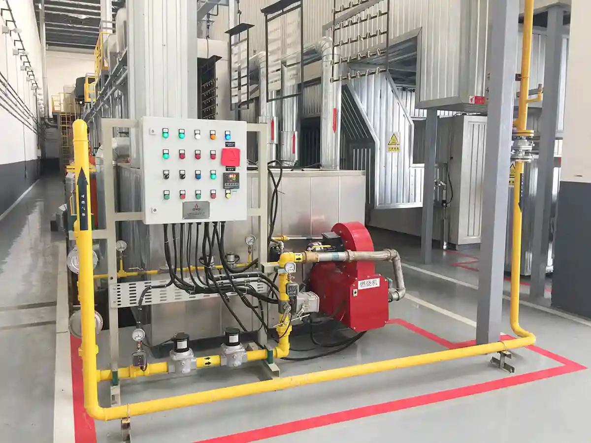
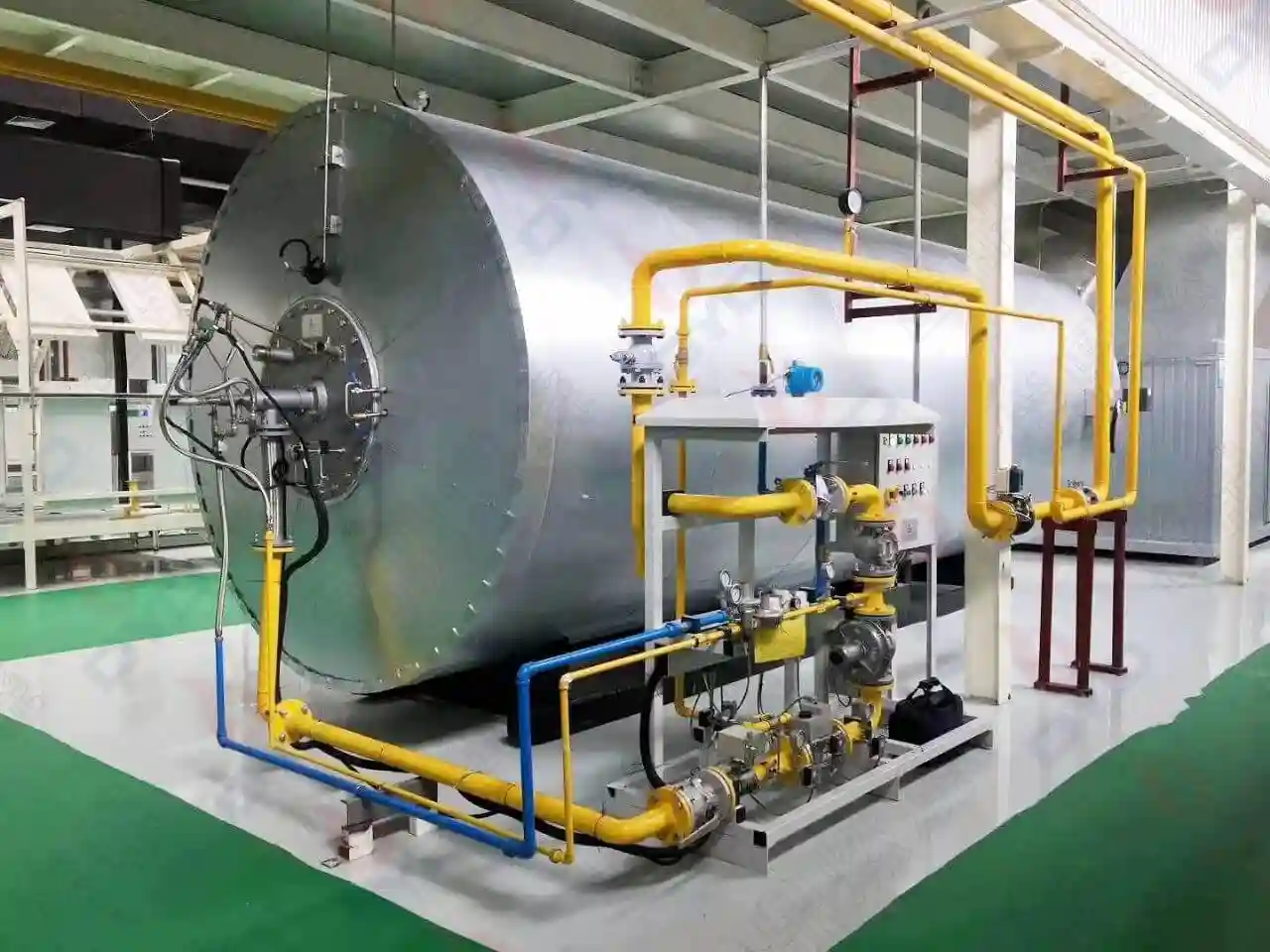
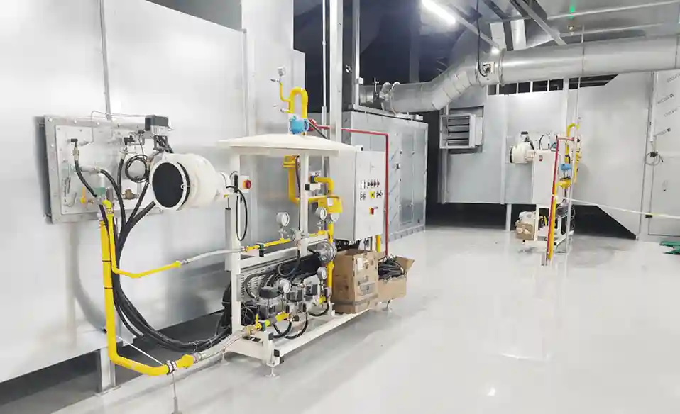
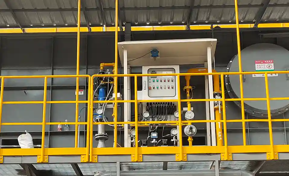
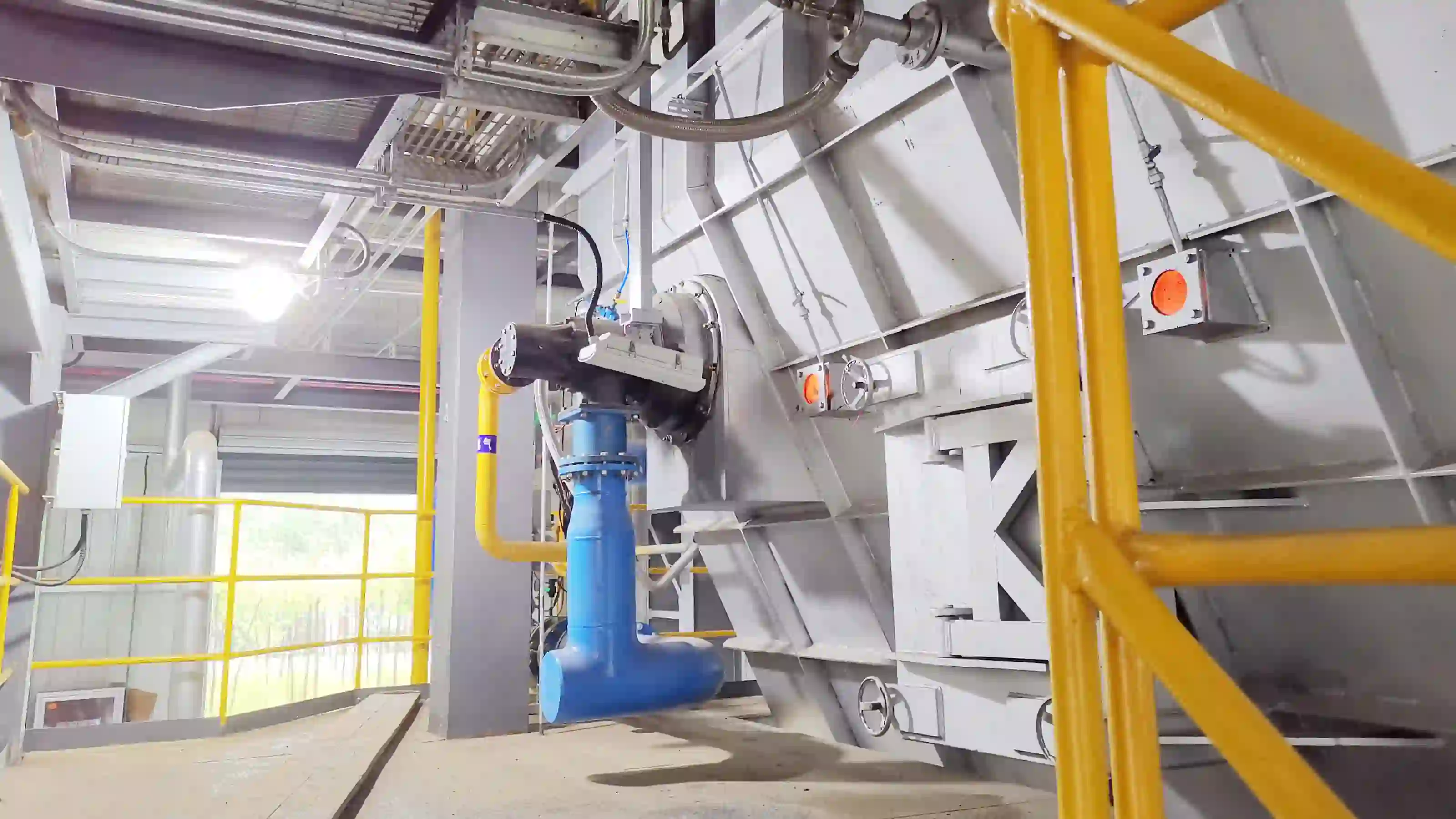
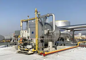
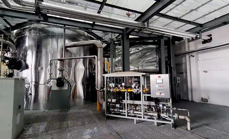
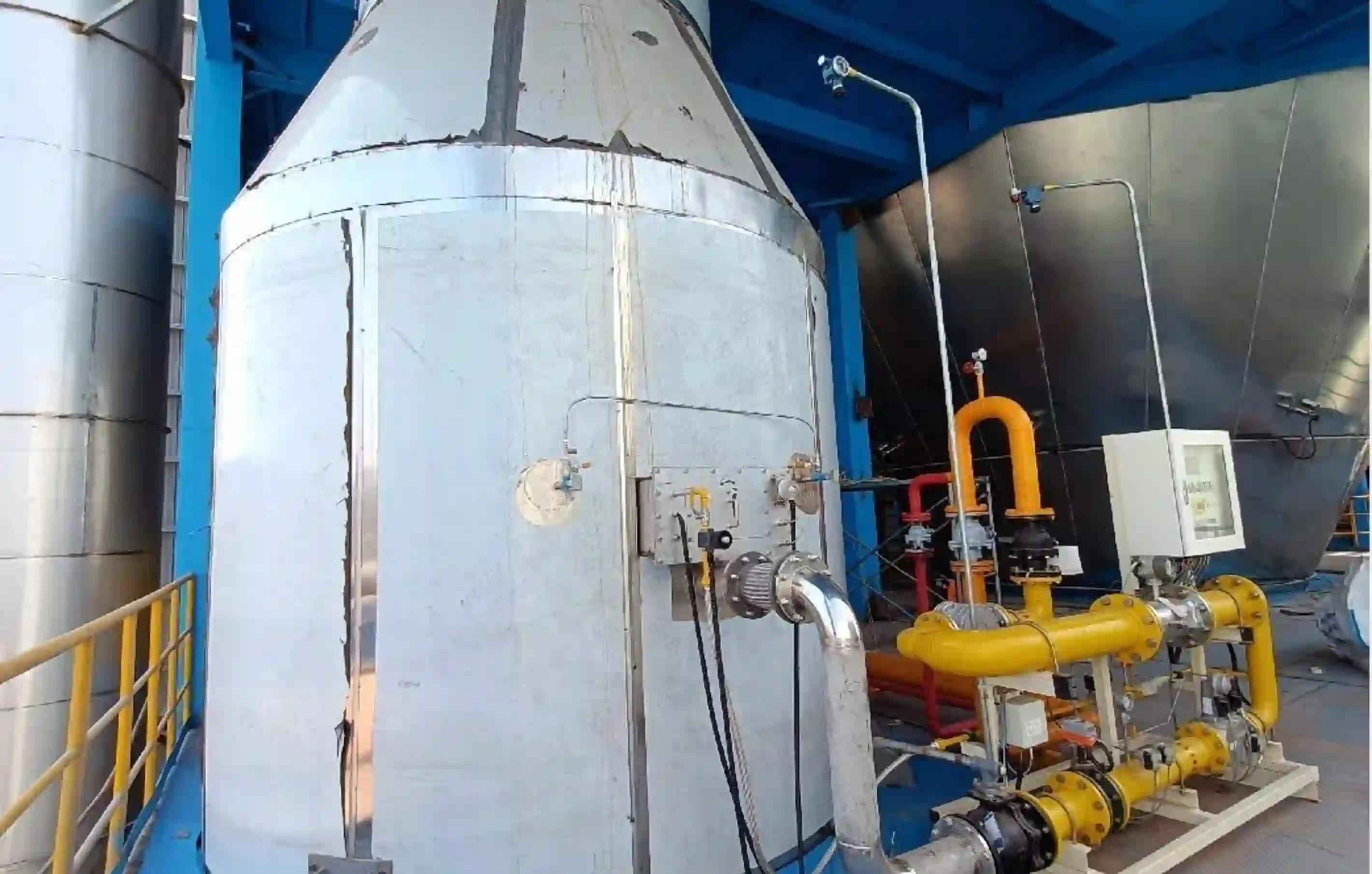
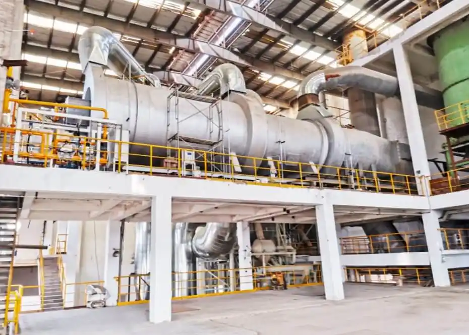
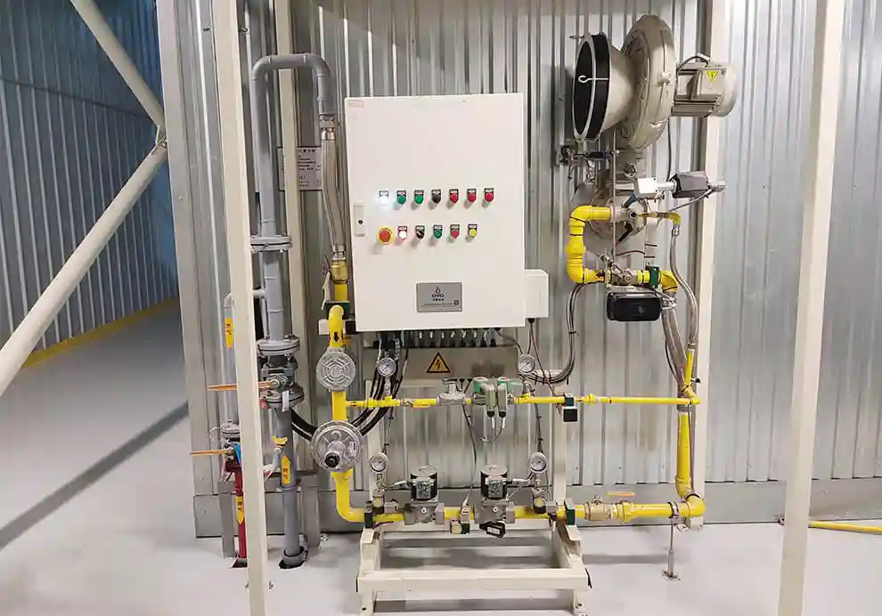
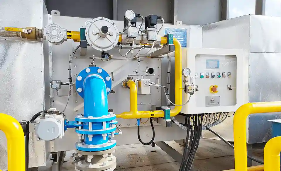
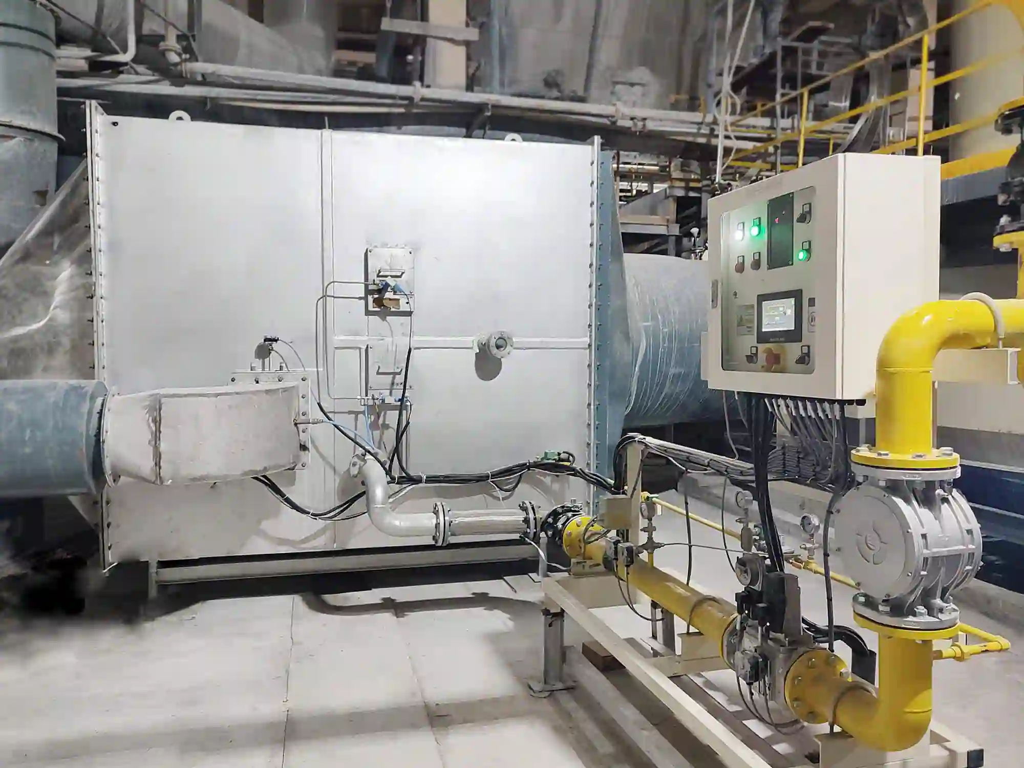
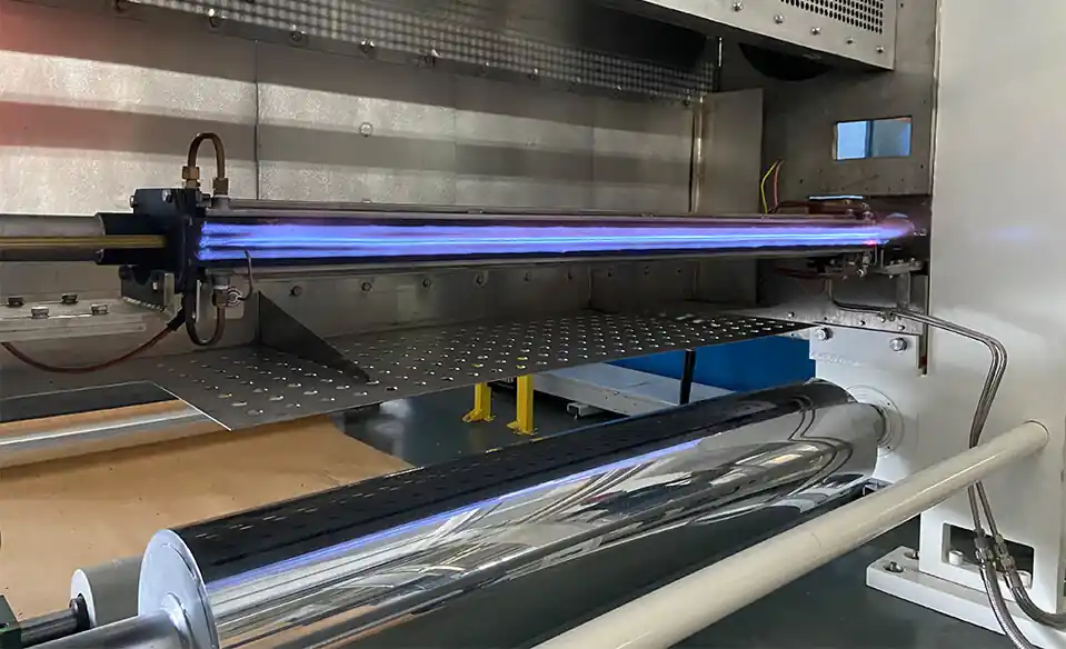
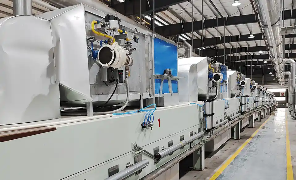
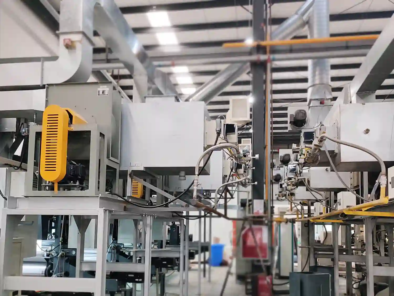
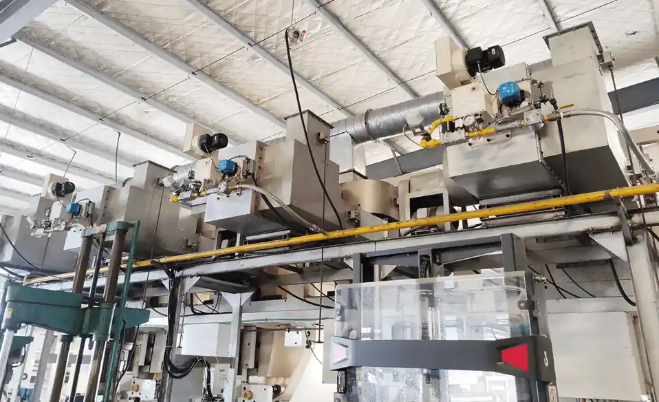
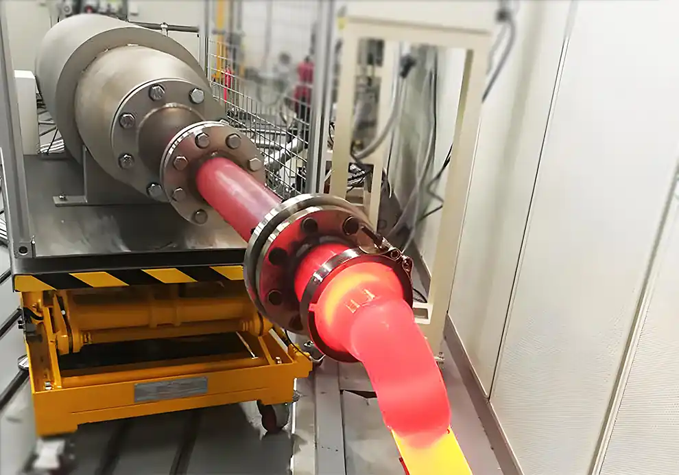
An industrial burner is more than a device that mixes fuel and air and produces a flame. It is a coordinated combustion system made up of multiple components that control fuel supply, combustion air, ignition, flame detection, safety, and operating conditions. Each component has a specific role, and the overall performance of the burner depends on how well these components work together.
The exact configuration varies depending on the fuel, thermal capacity, furnace design, operating temperature, and application. A gas burner for an industrial furnace, for example, may have a different configuration from a burner used in a drying system, hot air generator, RTO, or heat-treatment furnace. Even within the same category, burner designs can differ significantly based on control requirements, emissions limits, and safety standards.
Understanding the main components of an industrial burner is important when selecting, installing, troubleshooting, or upgrading a combustion system. It also helps engineers evaluate whether a burner package is complete and properly matched to the process. This article explains the main components, their functions, and the factors that influence their selection.
The burner body is the main structural part of the burner assembly. It serves as the mounting platform and the central housing for many other components. It supports or integrates components such as the combustion head, fuel inlet, air inlet, ignition system, and flame-detection components. Its design also influences how fuel and combustion air enter the combustion zone.
Depending on the application, burner bodies can be designed for different installation orientations, operating temperatures, pressure conditions, and furnace structures. For example, a burner mounted on the side wall of a furnace may have a different body configuration from one mounted on the roof or floor. The body may also include provisions for cooling air, inspection ports, or access to internal components.
A properly designed burner body should provide mechanical stability while maintaining the required combustion-air and fuel-flow paths. It should also be compatible with the furnace opening, refractory, and sealing arrangement to prevent air leakage or hot-gas escape. In many industrial burners, the body is made of cast iron, aluminum, or steel, depending on the temperature and mechanical requirements.
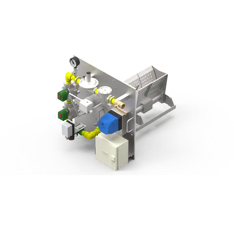
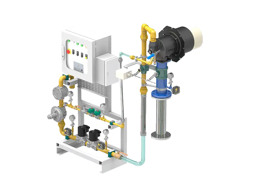
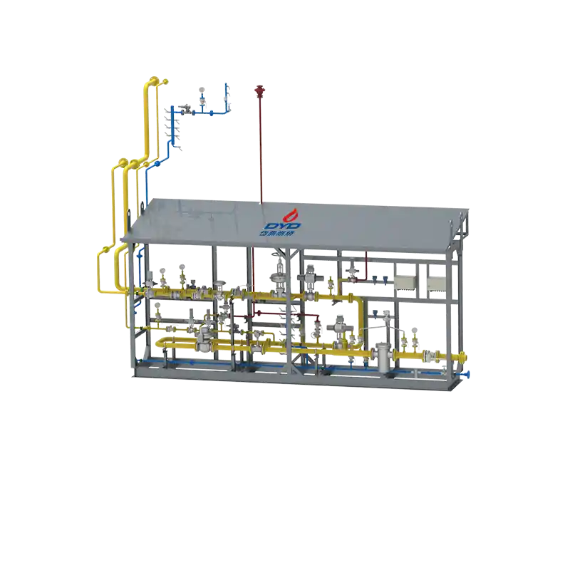
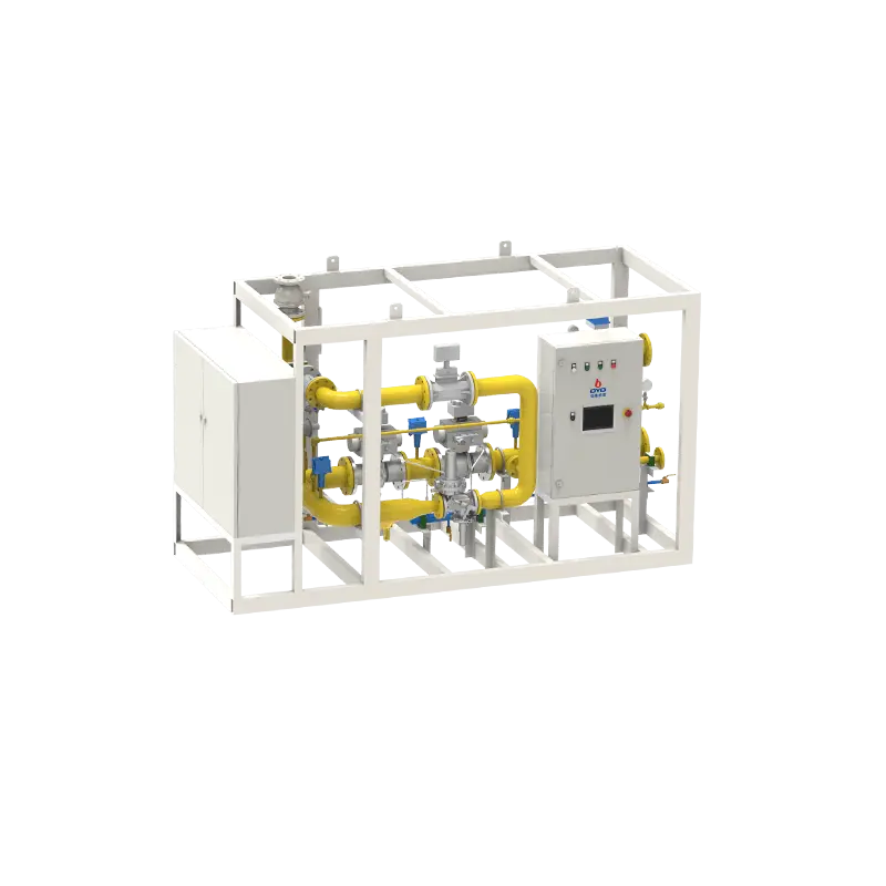
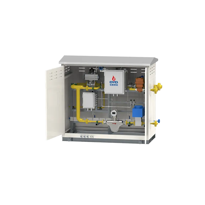
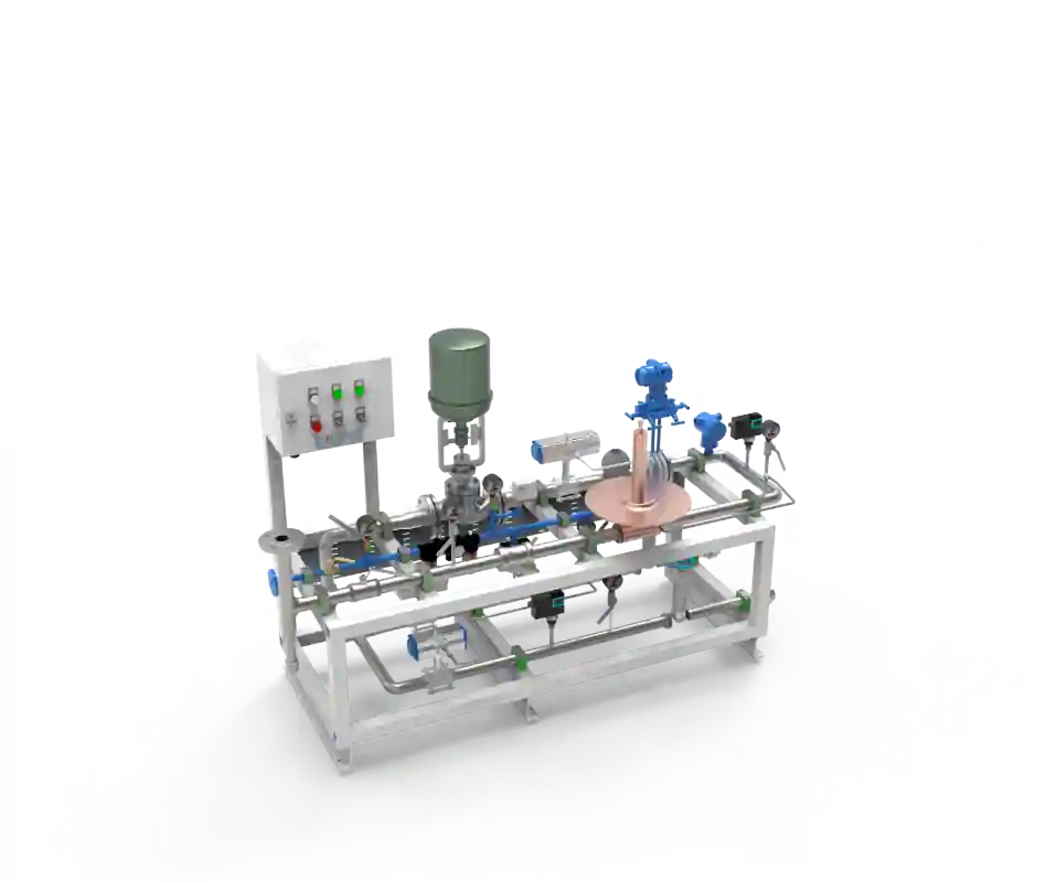
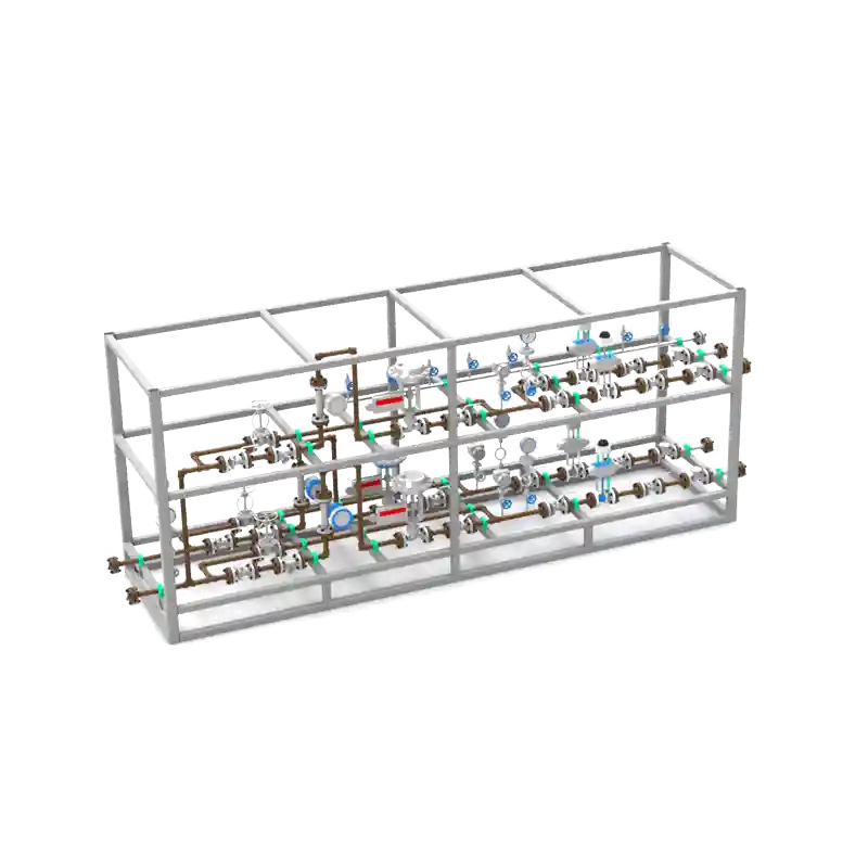
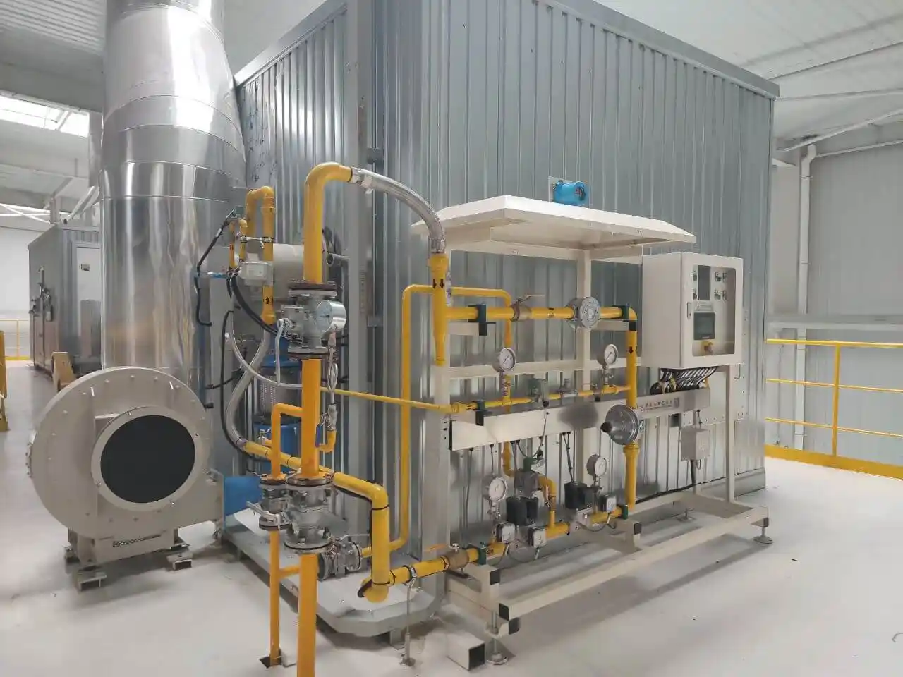
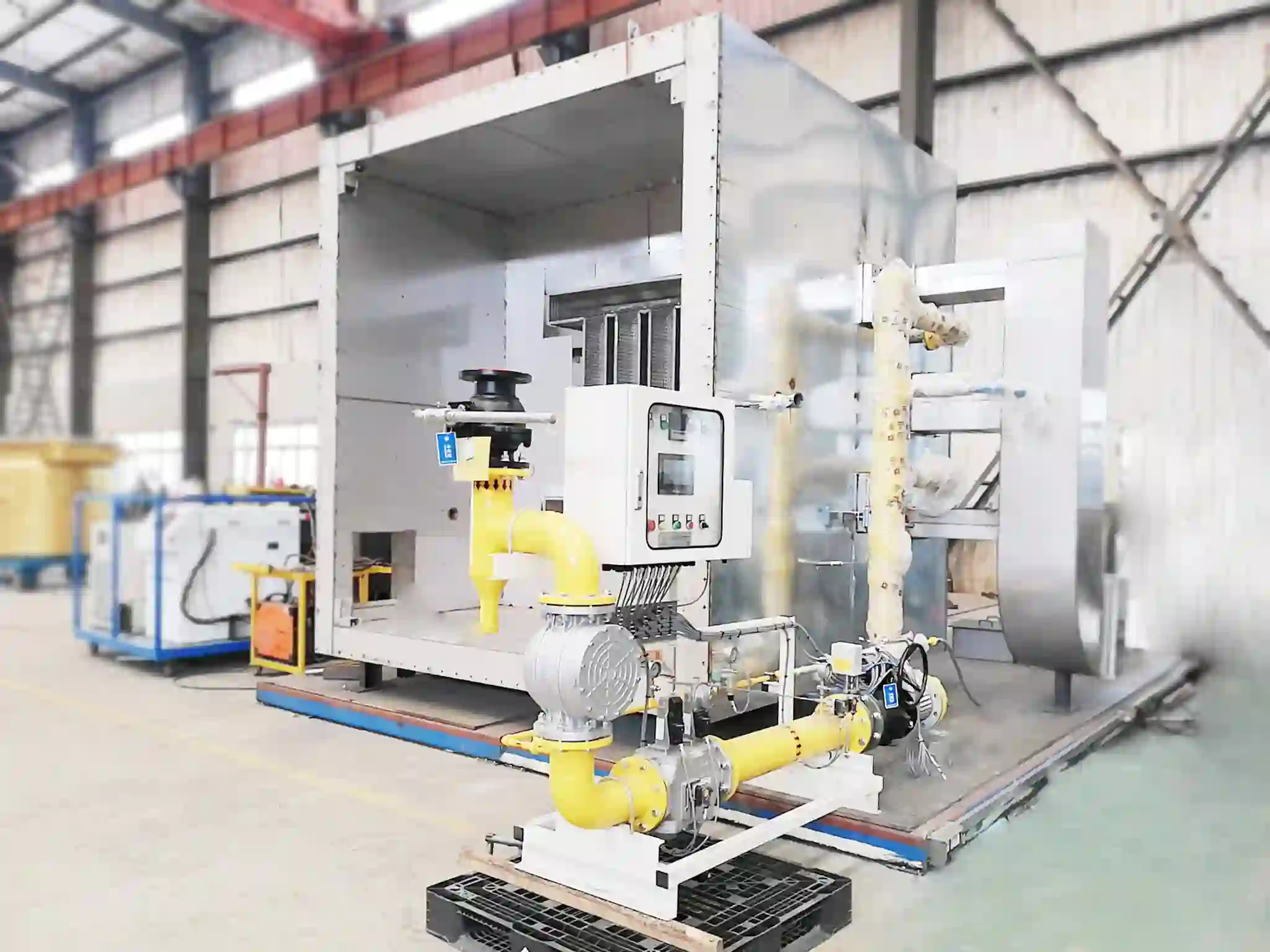
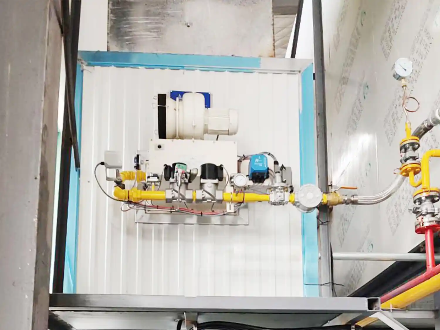
For gas-fired industrial burners, the fuel gas train controls and safeguards the supply of fuel gas to the burner. It is a critical part of the combustion system because it determines how fuel is delivered, regulated, and shut off. A typical gas train may include:
Manual shut-off valve
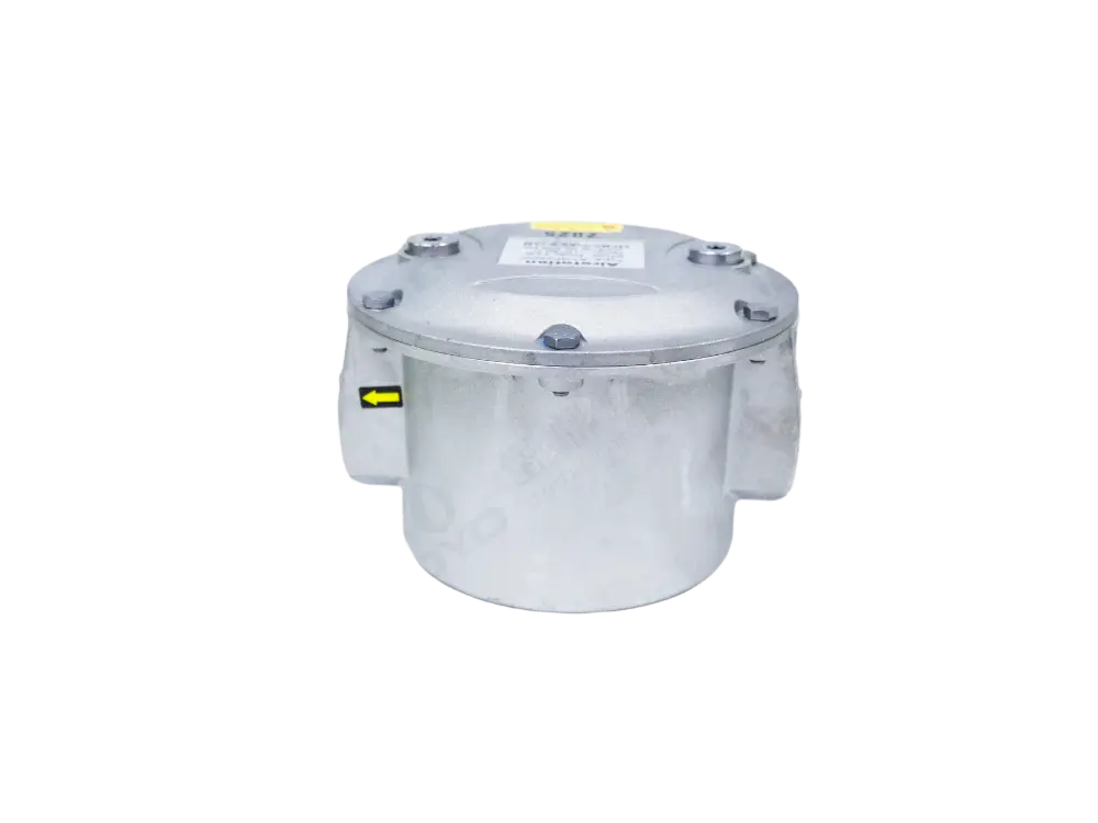
Gas filter
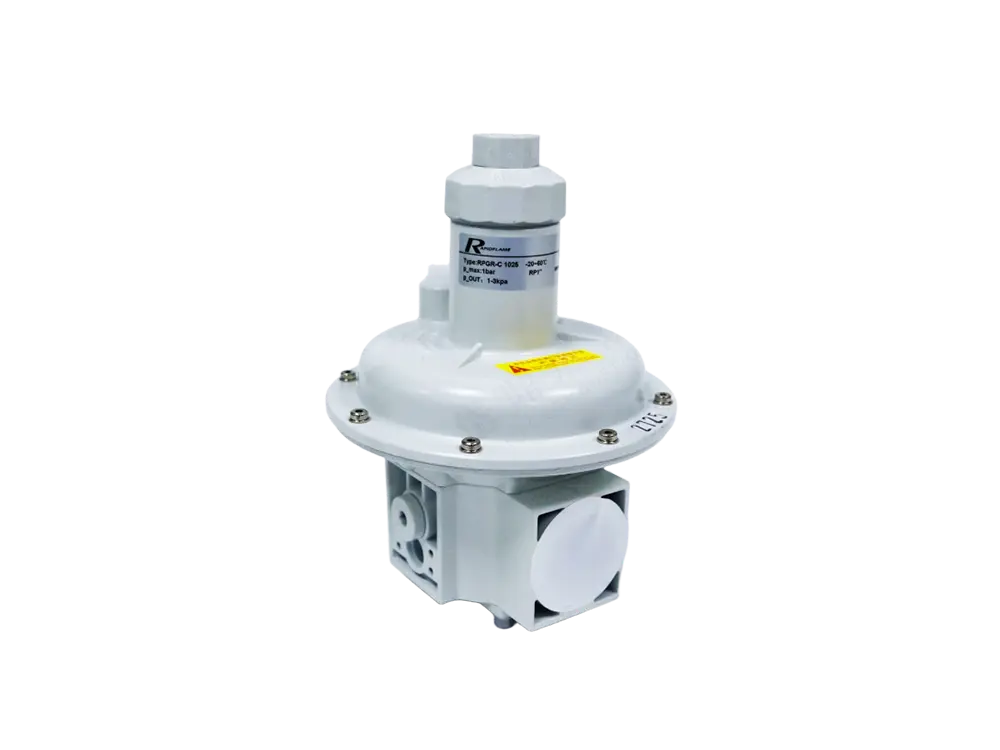
Pressure regulator
Solenoid safety valve
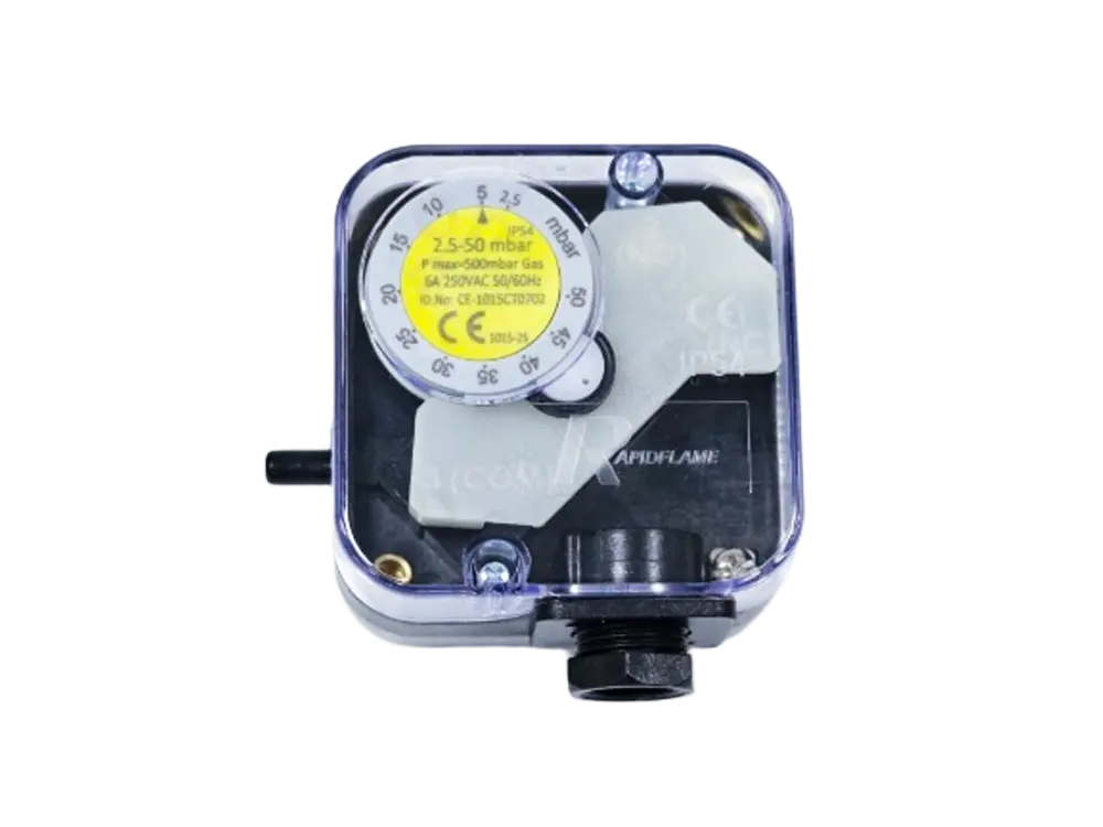
Pressure switch
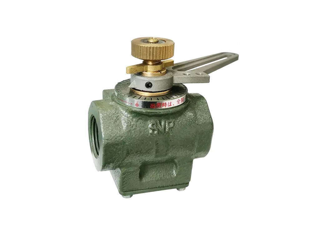
Control valve
Flexible connection or expansion joint
Pressure gauge
Gas piping and fittings
The exact configuration depends on burner capacity, fuel pressure, local regulations, safety requirements, and the overall combustion-system design. In some regions, the gas train must comply with specific standards such as EN 746-2, NFPA 86, or ISO 13577, which define the required safety components and testing procedures.
The gas train is particularly important because stable and controlled fuel pressure directly affects combustion stability. If the fuel pressure fluctuates, the burner may produce an unstable flame, incomplete combustion, or inconsistent heat release. Pressure regulators and safety shut-off valves help ensure that the burner receives fuel within the intended operating range and that fuel is quickly cut off in the event of a fault.
The fuel nozzle or gas outlet determines how fuel enters the combustion zone. It is one of the most important components affecting flame shape, stability, and mixing quality.
For liquid-fuel burners, the nozzle is responsible for atomizing fuel into smaller droplets so that it can mix effectively with combustion air. Atomization quality directly affects combustion efficiency and emissions. Poor atomization can produce large droplets that do not burn completely, leading to soot, CO, and unburned fuel.
For gas burners, the fuel outlet geometry controls the direction and velocity of gas entering the mixing zone. The gas may be injected through a single orifice, multiple orifices, or a specially shaped nozzle designed to promote mixing. Nozzle design can therefore affect:
Fuel-air mixing
Flame shape
Flame stability
Heat-release distribution
Combustion efficiency
Emissions
The nozzle should be selected according to fuel characteristics, burner capacity, operating pressure, and application requirements. In some cases, the nozzle may be replaceable so that the burner can be adapted to different fuels or operating conditions.
Combustion air provides the oxygen required for fuel combustion. Without sufficient air, the fuel cannot burn completely, and the burner will produce CO and unburned hydrocarbons. With too much air, the exhaust volume increases, and heat loss rises.
Industrial burners may receive combustion air from a dedicated fan, blower, compressed-air system, or another air-supply arrangement. In some cases, the combustion air is drawn from the surrounding environment by the burner’s own fan; in others, it is supplied by a central air system.
Important parameters include:
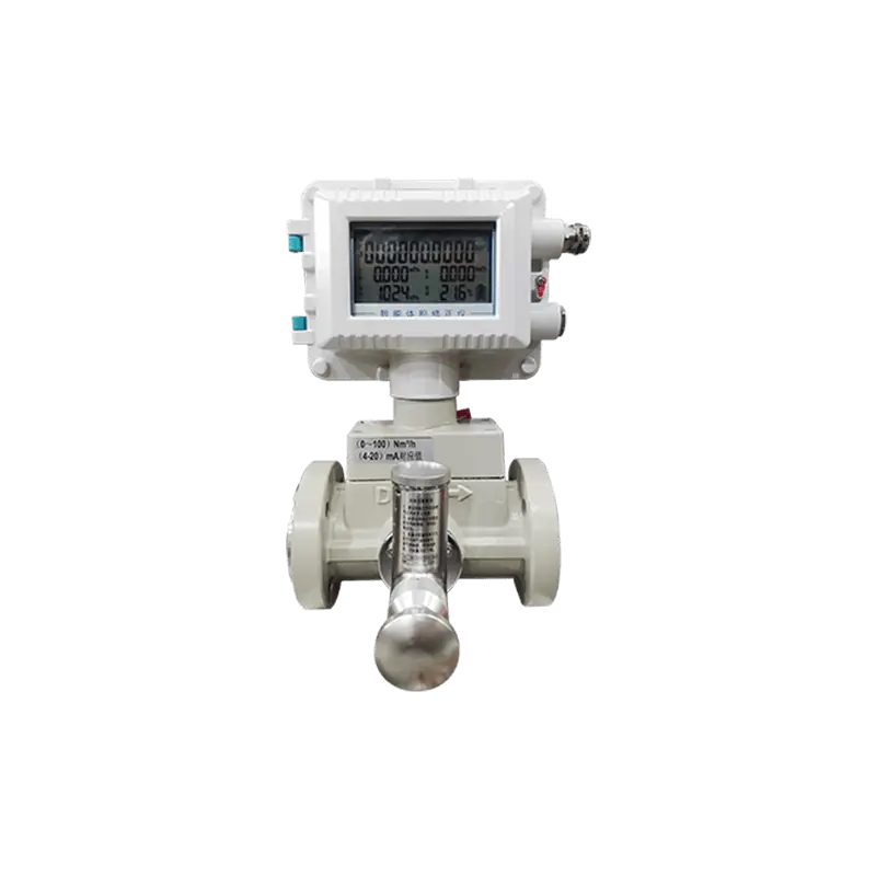
Airflow rate
Air pressure
Air temperature
Air-fuel ratio
Air velocity
Air distribution
The combustion-air system must provide sufficient air across the entire operating range without introducing unnecessary excess air. This means the air flow must be controllable and must follow the fuel flow as the burner modulates. Too little air can result in incomplete combustion, while excessive air can increase exhaust heat losses.
In high-temperature applications, combustion air may be preheated by a heat recovery system. This changes the air density and requires the burner and control system to be designed accordingly.
The air-control device regulates the amount of combustion air entering the burner. Depending on the burner design, this may be a mechanical damper, motorized actuator, control valve, variable-speed fan, or another flow-control mechanism.
For modulating burners, precise air control is particularly important because combustion-air flow needs to change together with fuel flow. If the air flow does not track the fuel flow accurately, the air-fuel ratio can drift, causing either incomplete combustion or excessive excess air.
A properly configured air-control system helps maintain the desired combustion conditions from minimum to maximum firing rate. It also allows the burner to respond smoothly to changes in process heat demand. In some systems, the air damper is linked mechanically to the fuel valve; in others, separate actuators are used with electronic ratio control. The choice depends on the required accuracy, turndown ratio, and safety requirements.
The mixing system is where fuel and combustion air are brought together under controlled conditions. The quality of mixing has a direct effect on combustion efficiency, flame stability, and emissions.
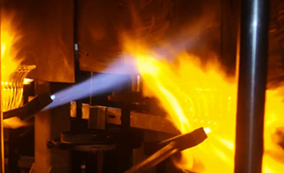
Different burner designs use different mixing principles. Some mix fuel and air before ignition (premixed combustion), while others maintain separate flows until they reach the combustion zone (diffusion combustion). Partial premixing is also common. The mixing configuration influences:
Flame velocity
Flame shape
Ignition characteristics
Combustion stability
Heat-release distribution
NOx formation
The appropriate mixing method depends on the fuel, burner type, furnace geometry, and process requirements. For example, a premixed burner may produce a shorter, more intense flame, while a diffusion burner may produce a longer, more luminous flame. In some applications, staged mixing is used to reduce NOx by controlling the local oxygen concentration and flame temperature.
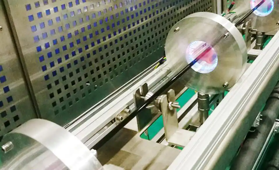
The combustion head is located near the flame outlet and plays an important role in flame formation. It is sometimes called the burner head or flame holder. Its geometry determines how the fuel-air mixture enters the furnace and how the flame develops.
Depending on the design, the combustion head may influence:
Flame length
Flame diameter
Flame velocity
Flame recirculation
Heat distribution
Flame stability
This is why a burner with the correct thermal capacity can still perform poorly if its flame characteristics are not suitable for the furnace. A flame that is too long may impinge on the opposite wall; a flame that is too short may concentrate heat near the burner. The combustion head should therefore be selected or adjusted to match the furnace geometry and process requirements.
In many industrial burners, the combustion head includes a swirler or stabilizer that imparts a rotational motion to the air, improving mixing and flame stability. The head may also be made of heat-resistant materials such as stainless steel or ceramic to withstand high temperatures.
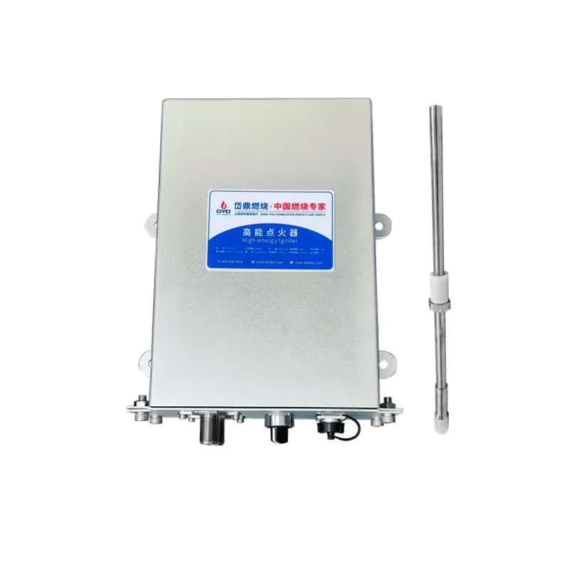
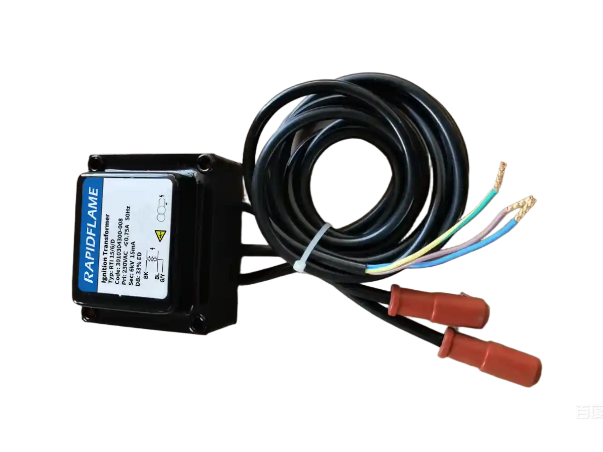
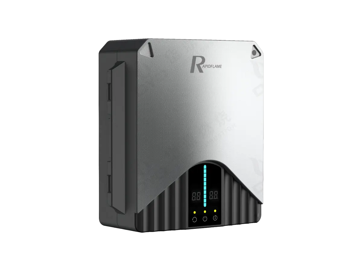
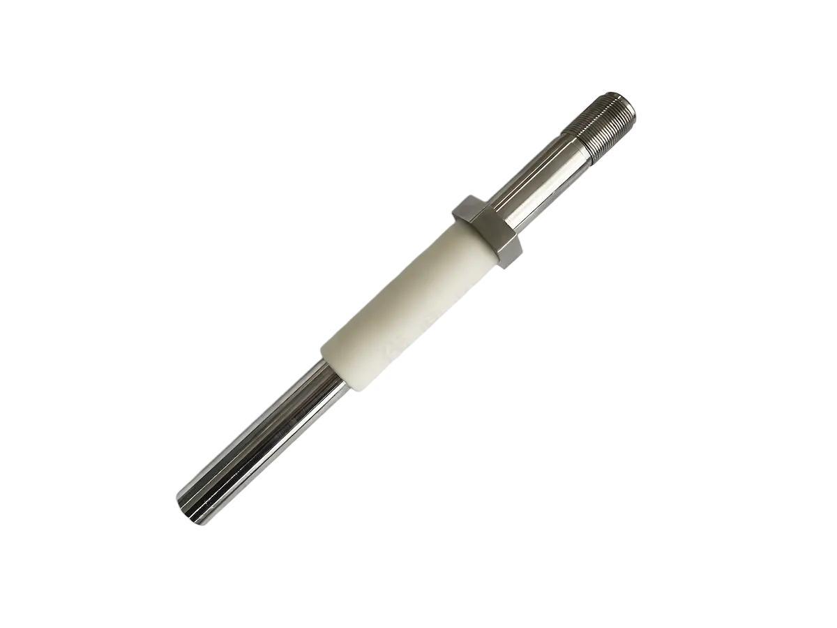
The ignition system starts the combustion process. It provides the initial energy needed to ignite the fuel-air mixture. A typical industrial burner ignition system may include:
Ignition transformer
Ignition electrode
Ignition cable
Ignition rod
Pilot burner
Ignition controller
During the start-up sequence, the ignition system generates the required ignition source while the burner control system manages the fuel and air sequence. The pilot flame, if used, provides a small stable flame that ignites the main burner. In direct spark ignition, the main burner is ignited directly by the spark.
Reliable ignition is especially important for industrial applications where burners start and stop frequently or operate under demanding conditions. A weak spark, fouled electrode, or incorrect gap can cause ignition failures, leading to repeated purge cycles, wasted fuel, and potential safety hazards. Regular maintenance of the ignition system is therefore essential.
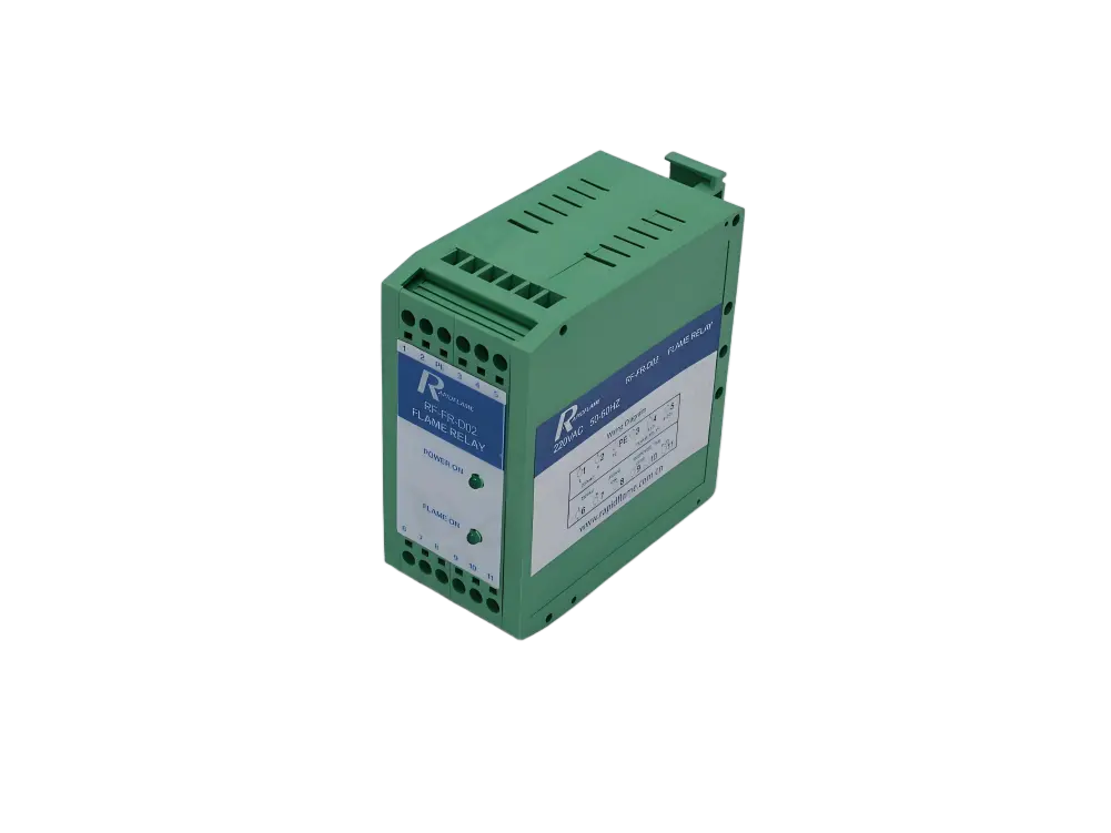
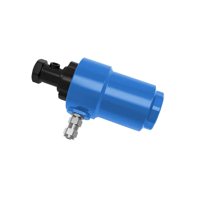
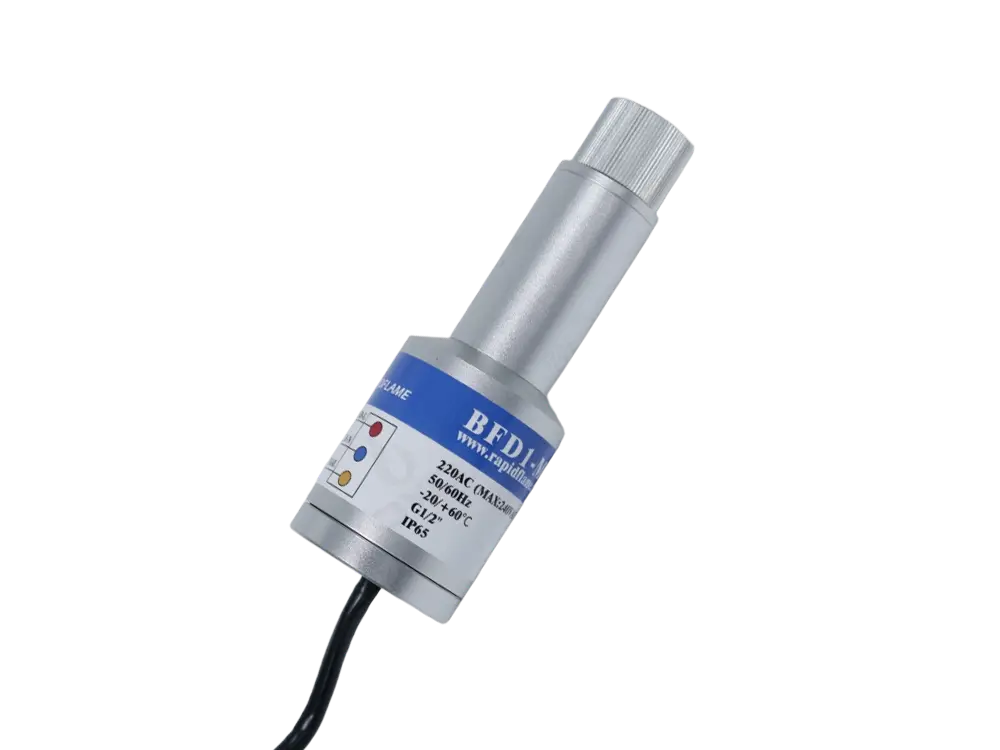
A flame detector confirms whether a stable flame is present. It is a critical safety component. Common technologies include:
UV flame detectors
Infrared flame detectors
UV/IR flame detectors
Ionization-based flame detection
The detector sends a flame-status signal to the burner control system. If the expected flame signal is not detected, the safety system can shut off the fuel supply according to the programmed safety sequence. This prevents unburned fuel from accumulating in the furnace, which could cause an explosion.
Flame detection is therefore not simply a monitoring function. It is an important part of burner safety. The detector must be selected for the fuel, flame characteristics, and operating environment. It must also be positioned correctly so that it can “see” the flame without being affected by background radiation or hot surfaces. Regular cleaning and testing of the flame detector are necessary to maintain reliable operation.
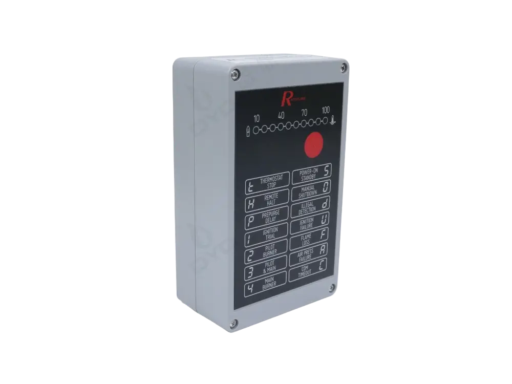
The burner controller manages the burner operating sequence. It is sometimes called a burner management system (BMS) or flame safeguard control. Depending on system complexity, it can coordinate:
Pre-purge
Airflow verification
Ignition
Pilot flame establishment
Main fuel valve opening
Flame verification
Normal operation
Flame failure response
Emergency shutdown
More advanced burner management systems can also integrate temperature control, pressure monitoring, oxygen control, and other process signals. They may communicate with a PLC or plant control system for remote monitoring and data logging.
The controller should be selected according to burner capacity, safety requirements, control philosophy, and applicable standards. It must be capable of executing the required safety sequence and responding correctly to fault conditions. In many industrial applications, the burner controller is a dedicated safety device that is separate from the process controller.
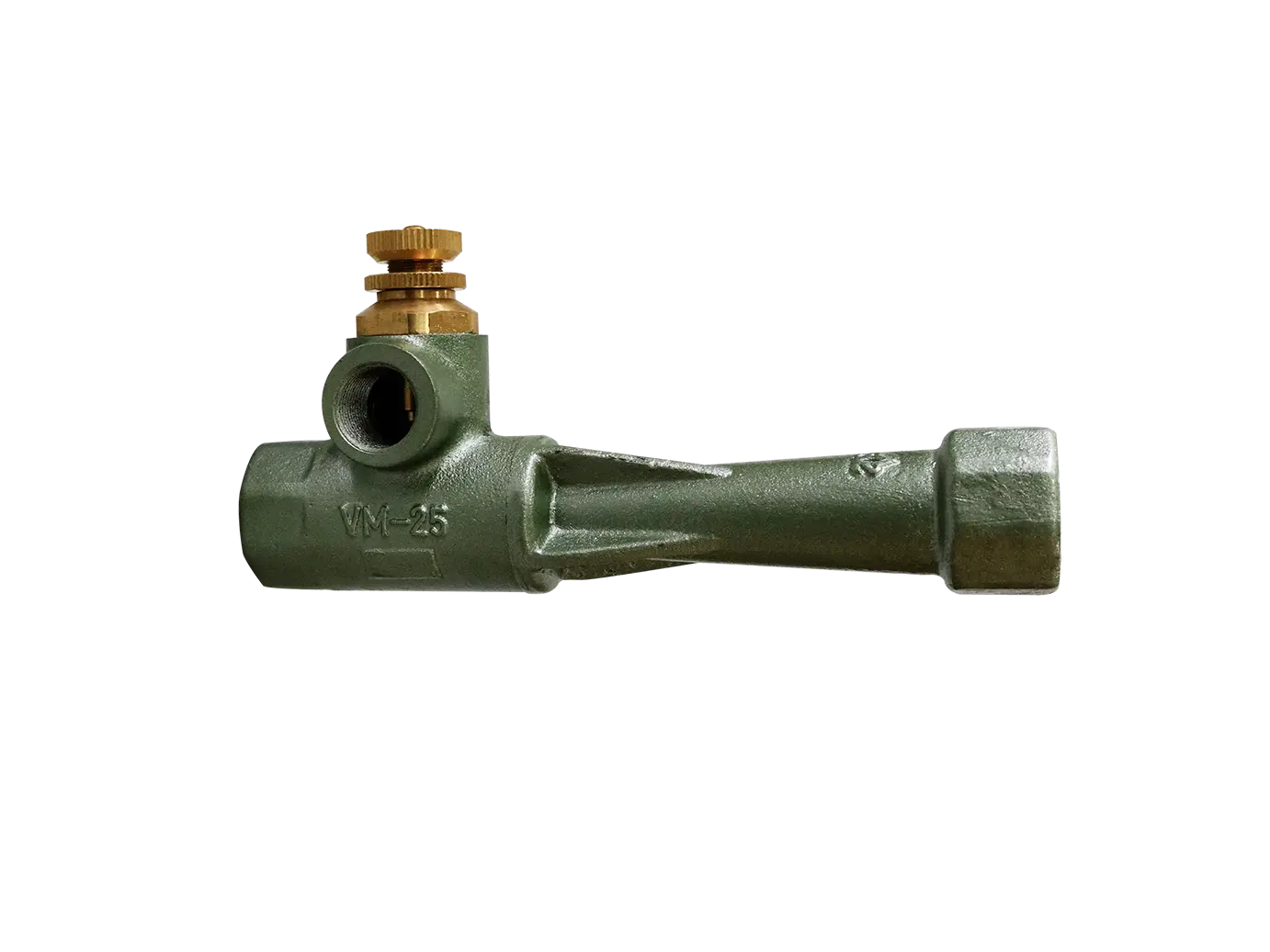
Stable fuel pressure is essential for consistent burner operation. A pressure regulator reduces and stabilizes the incoming gas pressure to the required operating range. It ensures that the burner receives fuel at the correct pressure regardless of variations in the supply line.
Pressure switches can monitor whether the fuel or air pressure is within an acceptable range. Typical functions include:
High gas-pressure protection
Low gas-pressure protection
Air-pressure verification
Fuel-pressure monitoring
Burner start-up interlock
These components help prevent the burner from operating under abnormal supply conditions. For example, if the gas pressure drops too low, the burner may not be able to maintain the required firing rate, and the flame may become unstable. If the gas pressure rises too high, the burner may overfire, causing overheating or safety problems. Pressure switches provide the signals needed to shut down the burner safely in these situations.
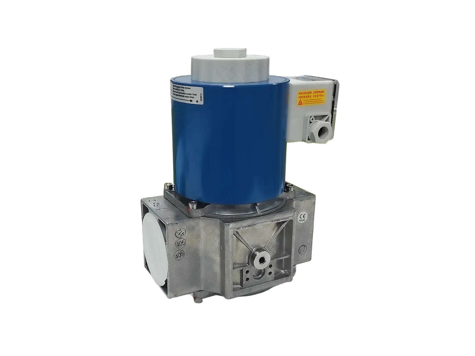
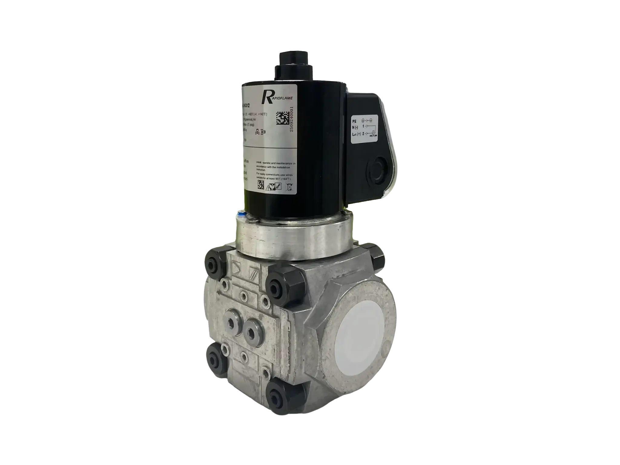
Solenoid valves are commonly used to shut off fuel quickly when the burner is stopped or a safety condition occurs. They are part of the fuel safety train and are typically designed to fail closed. This means that if power is lost or a fault occurs, the valve closes automatically and stops the fuel supply.
A typical safety sequence may require the fuel valves to remain closed until the appropriate start-up conditions have been confirmed. In the event of flame failure, abnormal pressure, or another defined fault condition, the safety valves can interrupt the fuel supply.
For this reason, solenoid safety valves are an important component of the burner fuel train and safety system. They must be selected for the fuel type, pressure rating, flow capacity, and required response time. Regular testing of the safety valves is part of a proper maintenance program.
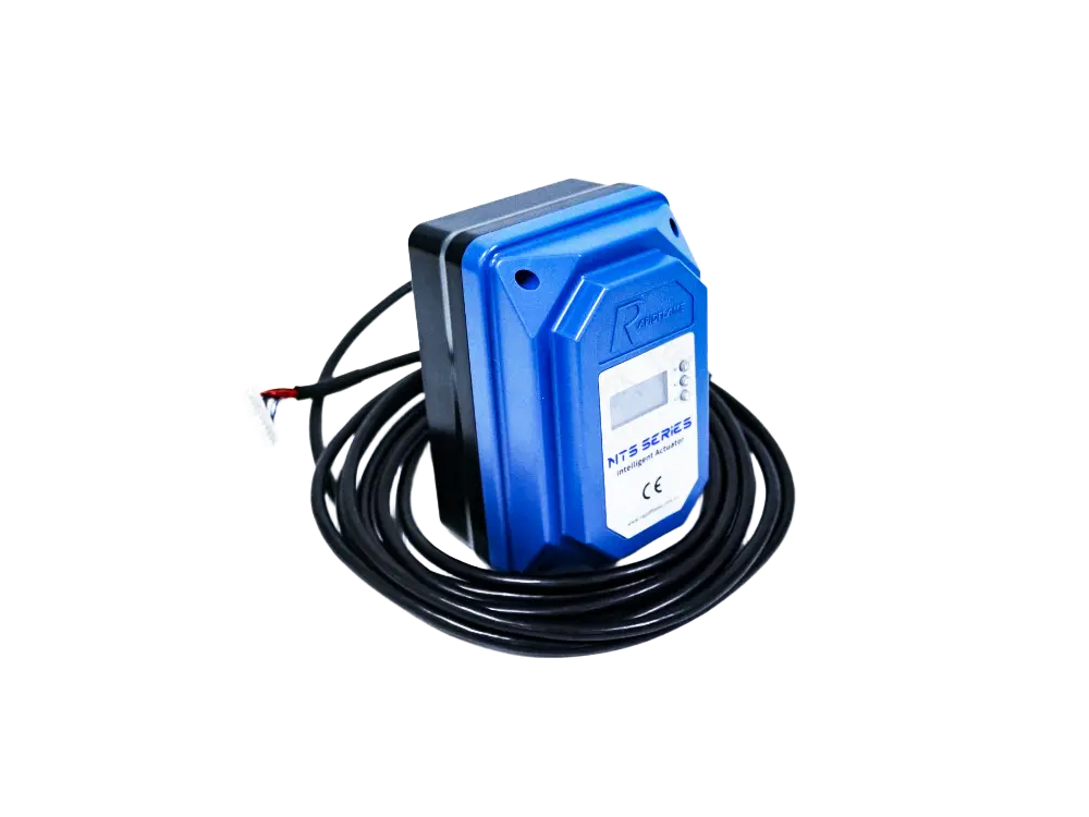
An electric actuator can be used to control an air damper, gas valve, or other modulating mechanism. It converts an electrical control signal into mechanical movement. For a modulating combustion system, the actuator changes the valve or damper position according to the control signal.
This allows the burner to adjust its firing rate as the process heat demand changes. The actuator's response speed, positioning accuracy, torque, and control signal should be matched to the application. In some systems, actuators are used for both fuel and air control, with electronic ratio control ensuring that the two remain in the correct relationship.
Electric actuators are available in different types, including on/off, floating, and modulating. The choice depends on the required control accuracy and the type of burner control system.
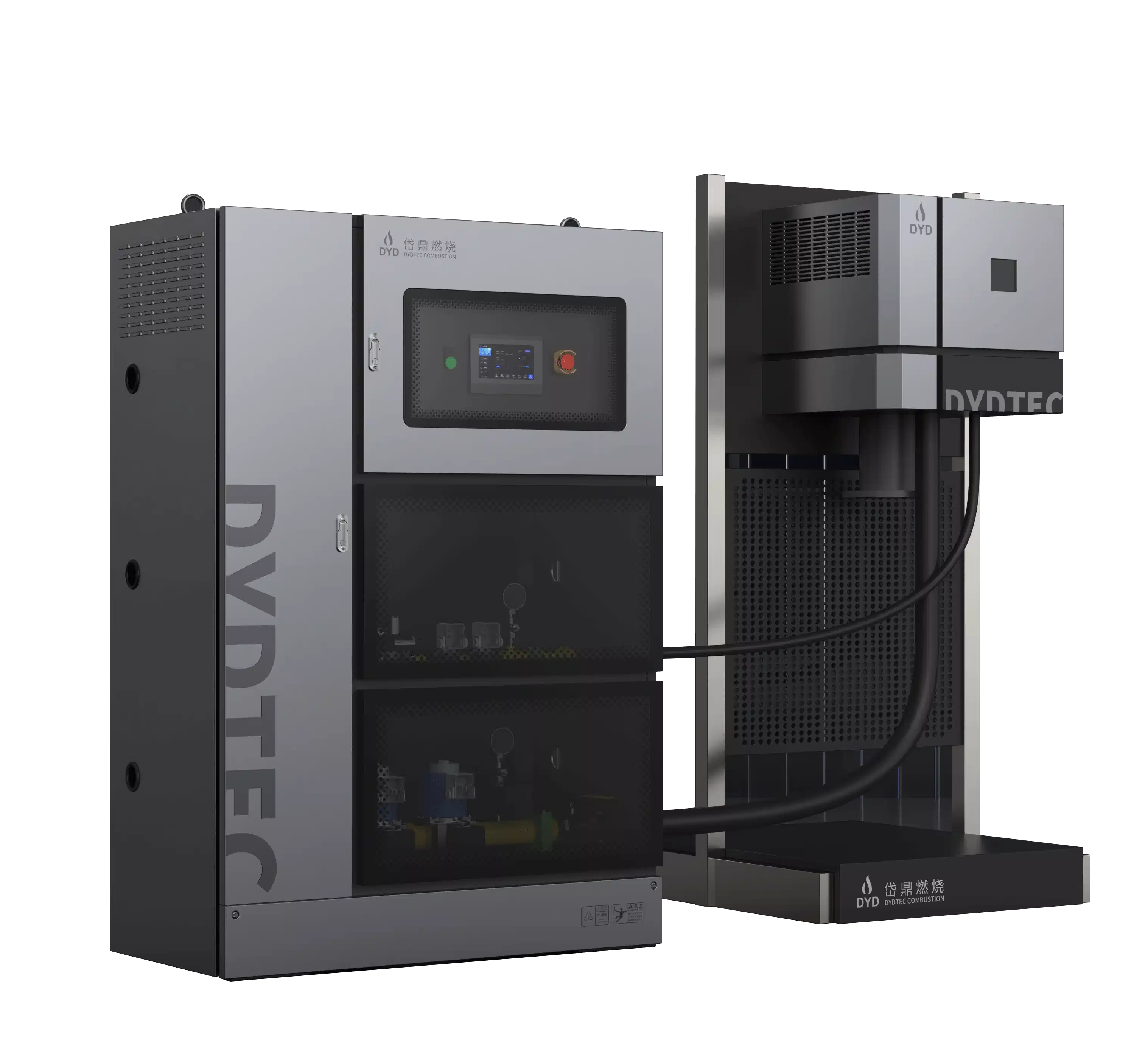
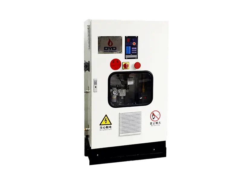
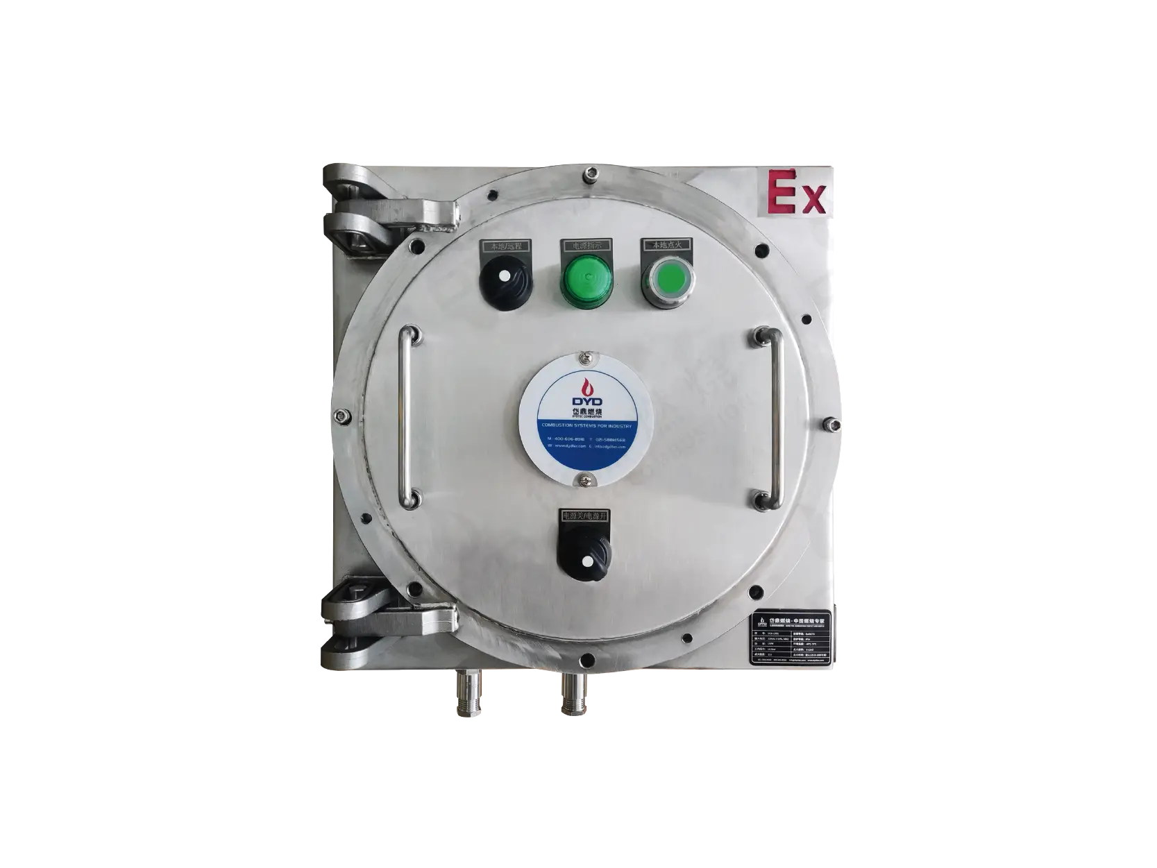
A complete industrial burner system may include a dedicated electrical control panel. This panel houses the electrical and electronic components that operate and monitor the burner. It can integrate:
Burner controller
Relays
Contactors
Circuit protection
Ignition control
Actuator control
Flame signal processing
Pressure switches
Temperature signals
Emergency-stop functions
Human-machine interface (HMI)
The control panel provides the interface between the burner and the wider industrial heating system. For complex applications, it can also communicate with a PLC or plant control system. The panel should be designed to meet the applicable electrical and safety standards, and it should be located in a suitable environment with adequate ventilation and protection.
Many industrial burners require a dedicated combustion-air fan or blower. The fan provides the pressure and airflow needed for combustion. It may be mounted directly on the burner or installed separately and connected by ductwork.
Fan selection should consider:
Required airflow
Static pressure
Furnace backpressure
Burner pressure drop
Air temperature
Operating range
Motor power
An incorrectly sized fan can cause combustion instability or prevent the burner from reaching its intended firing capacity. If the fan is too small, the burner may not receive enough air at high fire. If the fan is too large, the burner may operate with excessive air or require throttling, which wastes energy. Variable-speed drives can be used to match the fan output to the burner demand more efficiently.
Depending on the burner type, a flame tube or refractory-lined combustion section may be used between the burner and furnace. This component can help guide and stabilize the flame while protecting the burner structure from excessive thermal radiation.
Its dimensions and material should be compatible with the flame temperature, furnace temperature, installation geometry, and process conditions. In some burners, the flame tube is made of high-temperature stainless steel or ceramic. In others, the furnace refractory itself forms the combustion chamber interface.
The flame tube also affects the flame shape and heat release. If it is too small, the flame may become unstable or impinge on the tube wall. If it is too large, the flame may not stabilize properly. The burner manufacturer’s recommendations for flame tube dimensions should therefore be followed carefully.
Safety interlocks connect the burner to critical operating conditions. They ensure that the burner can only operate when all required safety conditions are satisfied. Typical interlocks can include:
Low gas pressure
High gas pressure
Low combustion-air pressure
Flame failure
High furnace temperature
Emergency stop
Fan failure
Valve-position verification
Furnace-pressure abnormality
The burner should only be allowed to operate when the required safety conditions are satisfied. If any interlock is not satisfied, the burner control system will prevent start-up or initiate a safe shutdown. Safety interlocks are an essential part of the burner system and must be designed, installed, and maintained in accordance with applicable standards.
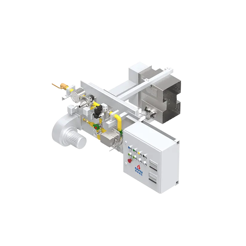
An industrial burner should be understood as an integrated system rather than a collection of independent parts. Each component depends on the others, and a fault in one component can affect the entire combustion process.
A simplified operating sequence looks like this:
Fuel supply → pressure regulation → safety shut-off → fuel control → fuel-air mixing → ignition → flame detection → combustion → heat transfer
At the same time:
Air supply → fan/blower → air control → burner mixing system → combustion zone
The burner controller coordinates these processes and continuously monitors the required safety signals. If any condition falls outside the safe operating range, the controller initiates the appropriate response, such as an alarm or shutdown.
This interaction is what allows the burner to provide stable and controllable heat. It also explains why burner troubleshooting often requires checking multiple components rather than focusing on a single part. For example, an unstable flame may be caused by fuel pressure variation, air damper problems, a dirty nozzle, or a flame detector fault. A systematic approach is needed to identify the root cause.
The major components can also be grouped according to their primary function. This classification is useful when evaluating whether a burner package includes all the components required for a complete combustion system.
| Function | Typical Components |
|---|---|
| Fuel supply | Gas train, filter, pressure regulator, piping |
| Fuel control | Control valve, solenoid valve, actuator |
| Air supply | Fan, blower, air damper |
| Fuel-air mixing | Mixing chamber, burner head, nozzle |
| Ignition | Ignition transformer, electrode, pilot |
| Flame monitoring | Flame detector, flame scanner |
| Safety | Pressure switches, safety valves, interlocks |
| Control | Burner controller, PLC, control panel |
| Combustion | Burner head, flame tube, combustion chamber |
| Process control | Temperature and pressure sensors |
This functional view helps engineers ensure that no critical component is missing and that each function is properly integrated into the overall system.
The correct components depend on the actual operating conditions. A component that works well in one application may not be suitable in another. Before selecting an industrial burner, engineers should determine:
Is the burner designed for natural gas, LPG, biogas, hydrogen-containing gas, diesel, or another fuel? Fuel properties affect nozzle design, mixing, combustion characteristics, and control requirements. For example, hydrogen has a higher flame speed and different combustion characteristics than natural gas, so the burner must be designed accordingly.
The burner must provide sufficient heat output for the required process load without being excessively oversized. The capacity range should match the actual heat demand profile, including startup, normal operation, and holding periods.
Available fuel pressure determines the appropriate gas-train configuration and burner design. If the fuel pressure is too low, the burner may not reach its rated capacity. If it is too high, additional pressure regulation may be required.
The furnace size, shape, burner position, and required flame coverage all affect burner selection. The burner must be matched to the furnace to ensure proper heat distribution and avoid flame impingement.
High-temperature applications may require special materials, refractory components, or cooling arrangements. The burner components must be able to withstand the furnace temperature and thermal cycling.
Some applications require simple on/off control, while others require multi-stage or fully modulating operation. The control system should be selected to match the process requirements and the desired level of automation.
Applications with strict NOx requirements may require specialized low-NOx combustion technology. The burner design and control strategy must be selected to meet the applicable emission limits while maintaining stable combustion.
Fuel shut-off, flame detection, pressure monitoring, purge sequences, and interlocks should be considered as part of the complete system. The burner must comply with the relevant safety standards and regulations for the application and region.
DYDTEC Combustion develops industrial combustion equipment and complete burner solutions for different thermal processes. Founded in 2012, DYDTEC Combustion has developed more than 100 burner models for applications across industrial furnaces, drying systems, hot-air equipment, RTOs, heat-treatment equipment, and other thermal processes.
Its approach considers the burner, fuel system, combustion air, control system, flame detection, furnace geometry, and operating conditions as an integrated system. This helps industrial users select burner configurations according to the actual requirements of their equipment rather than focusing only on burner capacity.
For OEM equipment manufacturers and industrial heating-system integrators, this system-oriented approach can be particularly valuable. The burner is not treated as an isolated component but as part of a complete thermal process. By considering the interaction between the burner and the furnace, DYDTEC Combustion can help customers achieve stable combustion, efficient heat transfer, and reliable operation. The company has production and R&D bases in Shanghai and Yangzhou and serves customers across more than 50 countries and regions.
There is no single component that determines burner performance. The burner head, fuel system, combustion-air system, ignition, flame detection, and control system must work together. A weakness in any one component can affect the entire combustion process.
A typical gas burner system may include a burner body, gas train, pressure regulator, safety solenoid valves, gas control valve, combustion-air system, ignition system, flame detector, burner controller, and related safety interlocks. The exact configuration depends on the application and local regulations.
The burner produces and controls the flame, while the burner management system controls the operating sequence and safety functions associated with the burner. The BMS ensures that the burner starts, operates, and shuts down safely.
A flame detector verifies that the expected flame is present. If flame failure occurs, the control system can initiate the appropriate safety shutdown sequence. This prevents unburned fuel from accumulating and creating an explosion hazard.
In many cases, individual components can be replaced, but compatibility is important. Replacement components should match the burner design, fuel, capacity, pressure, control system, and safety requirements. Using incompatible components can compromise safety and performance.
No. Burner configuration varies according to fuel, thermal capacity, furnace geometry, operating temperature, control method, emissions requirements, and application. A burner for a small drying oven may have a very different configuration from a burner for a large steel reheating furnace.
Inspection frequency depends on the application and operating conditions. High-temperature, continuous, or dusty applications may require more frequent inspections. As a general guide, burners should be inspected at least annually, with more frequent checks for critical components such as flame detectors and ignition systems.
Common causes include dirty or clogged nozzles, worn ignition electrodes, contaminated flame detectors, pressure switch drift, valve leakage, and actuator failure. Regular maintenance and monitoring can help prevent these problems.
The main components of an industrial burner include the burner body, fuel system, gas train, fuel nozzle or outlet, combustion-air system, mixing system, combustion head, ignition system, flame detector, burner controller, safety valves, pressure-control components, actuators, and control panel.
These components do not operate independently. Their interaction determines flame stability, heat distribution, combustion efficiency, emissions, and operational safety. A burner is only as good as its weakest component, and the system as a whole must be designed, installed, and maintained correctly.
For this reason, industrial burner selection should focus not only on the burner itself but also on the fuel supply, combustion air, control system, furnace geometry, process requirements, and safety architecture. A properly engineered burner system provides a more reliable foundation for stable and energy-efficient industrial heating. When all components are matched to the application and integrated as a complete system, the burner can deliver consistent performance, lower operating costs, and long-term reliability.