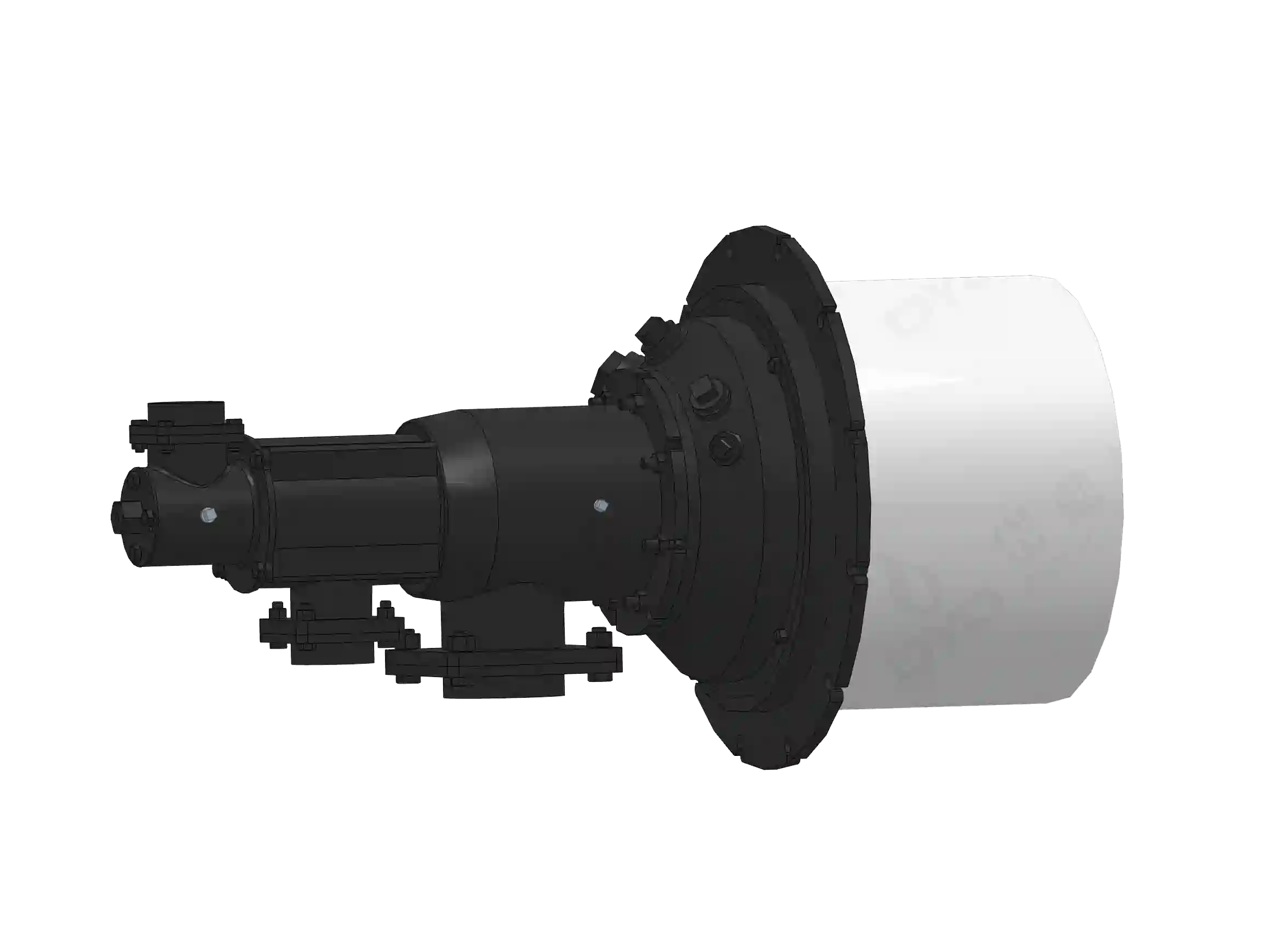
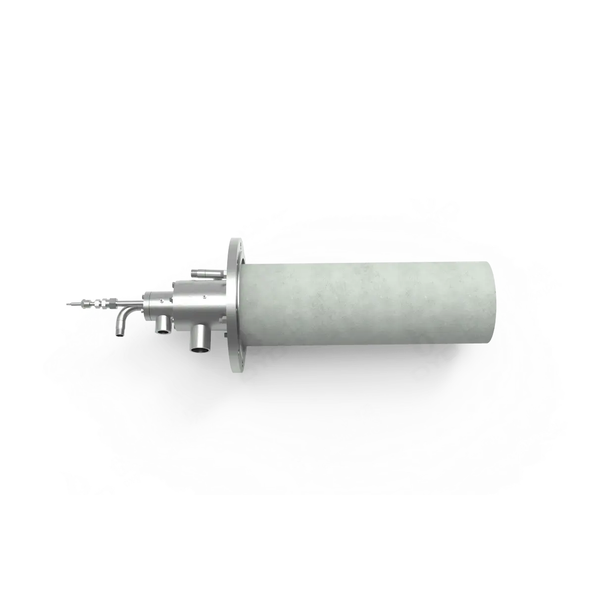
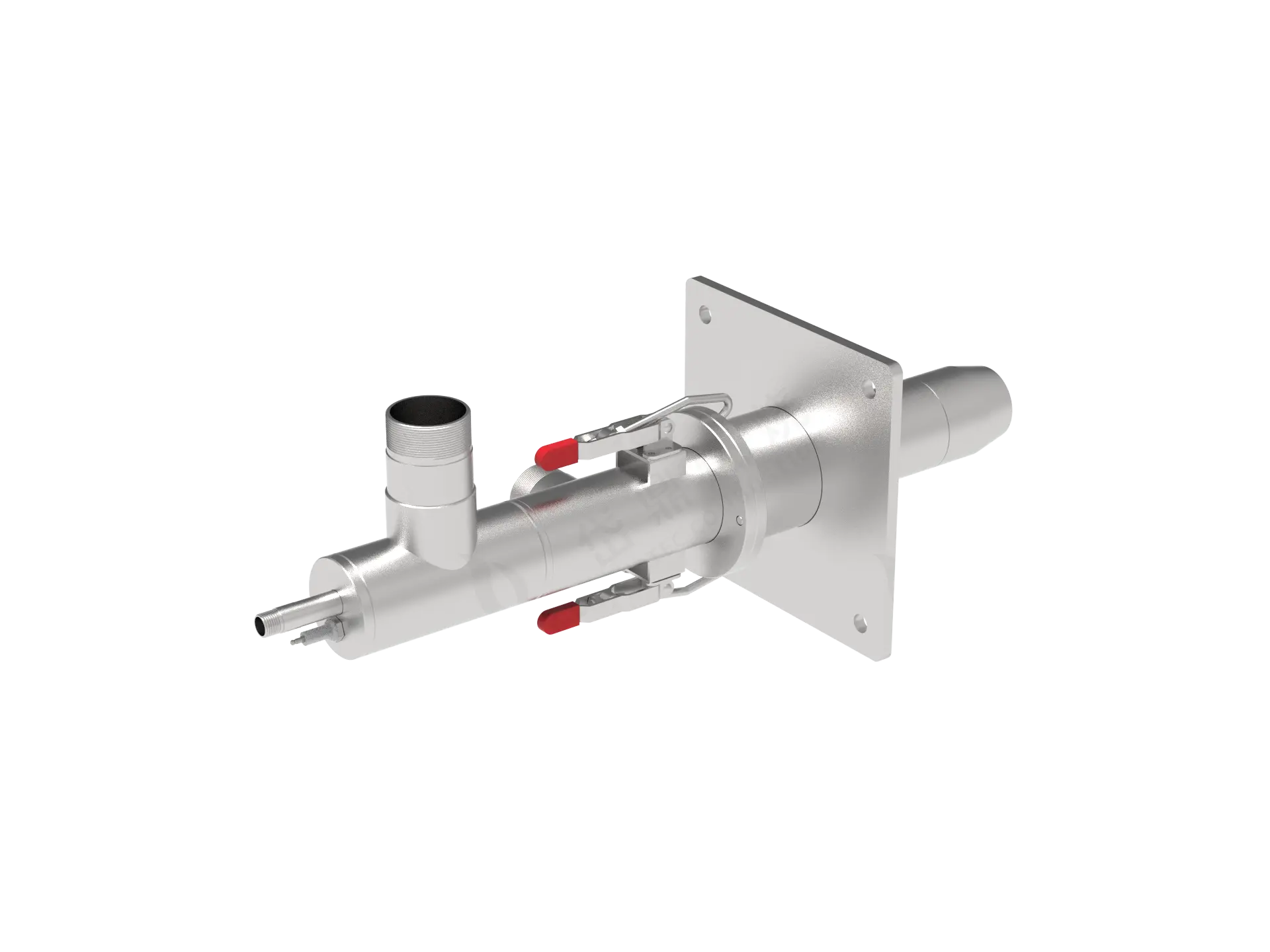
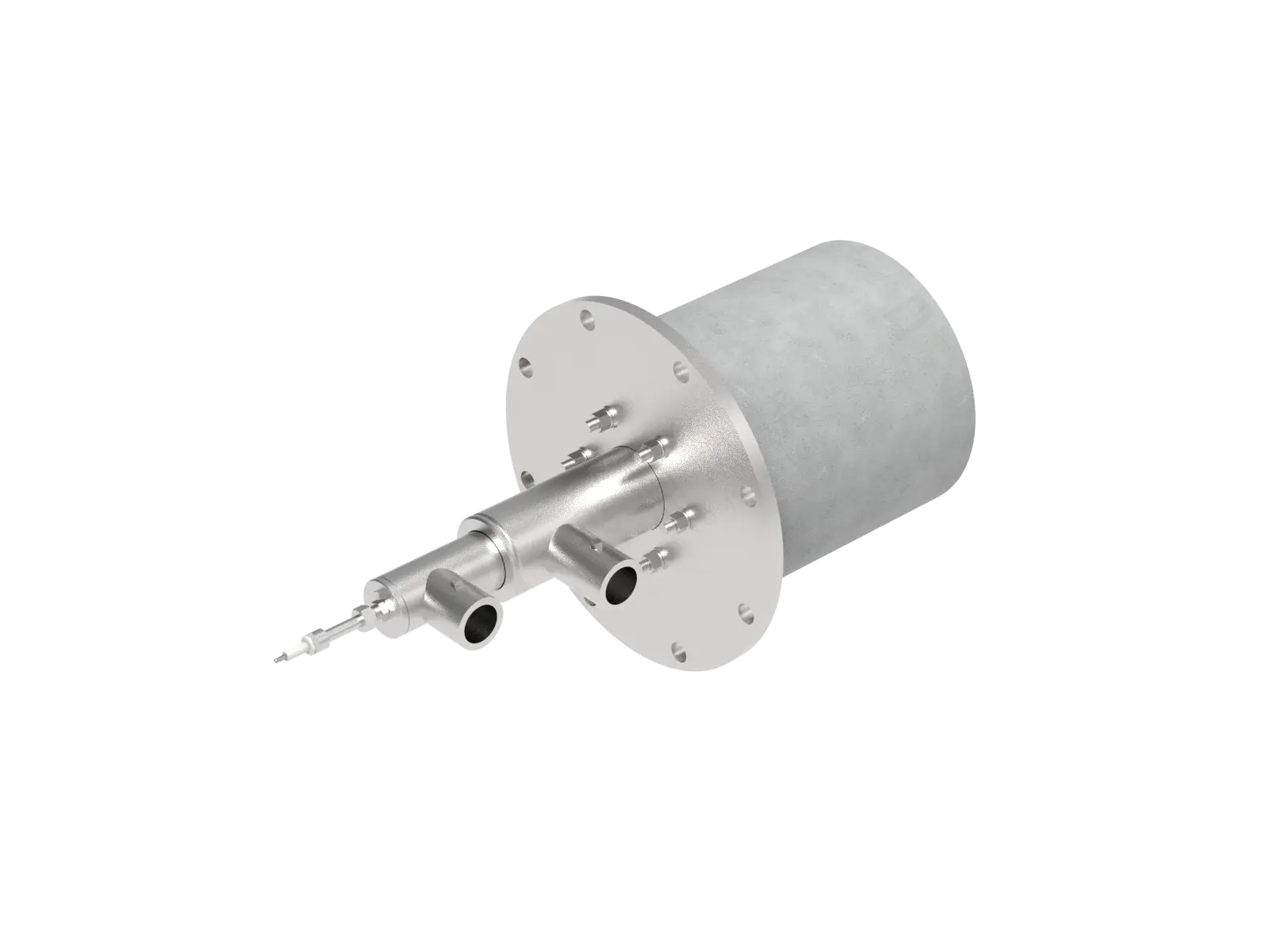
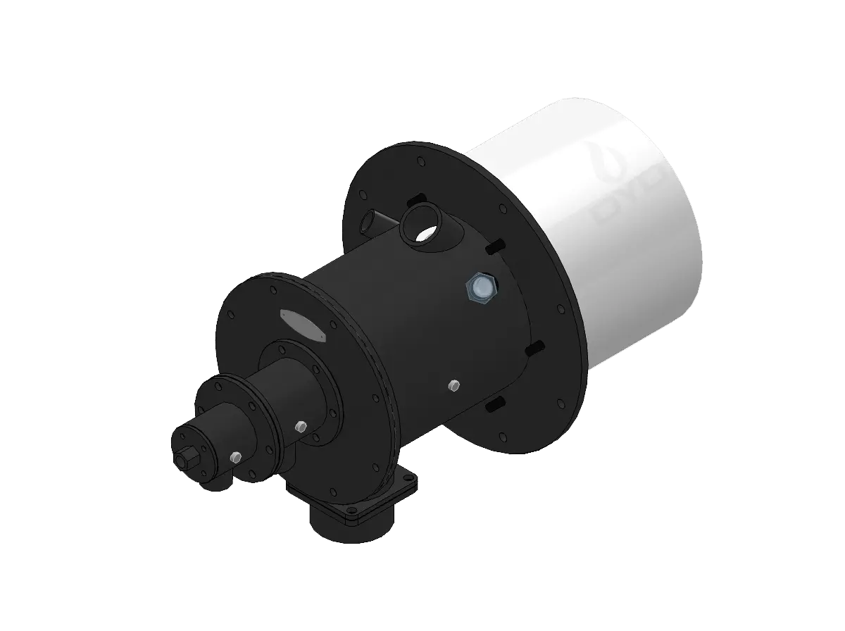
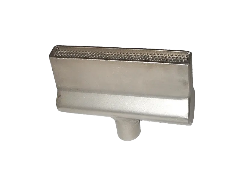
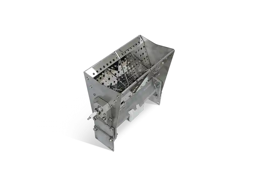
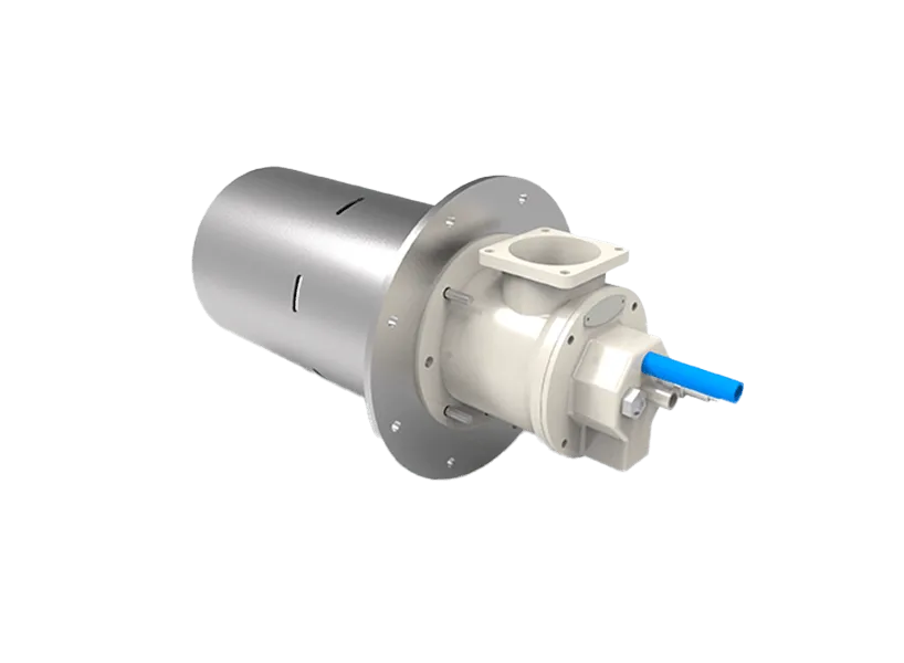
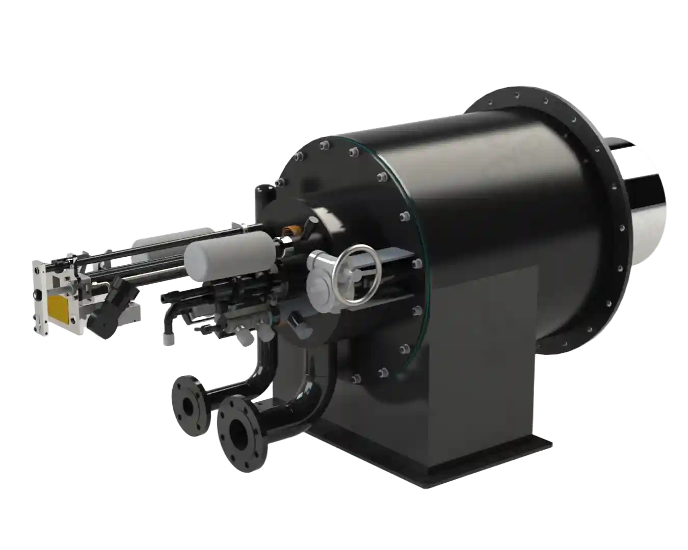
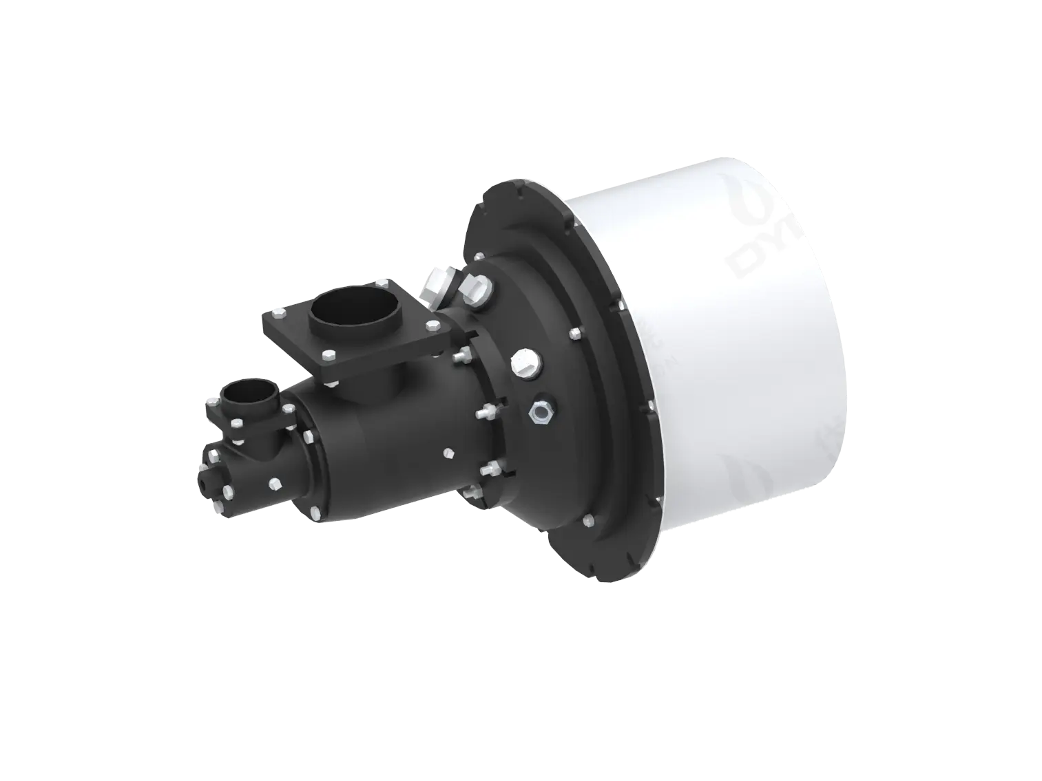
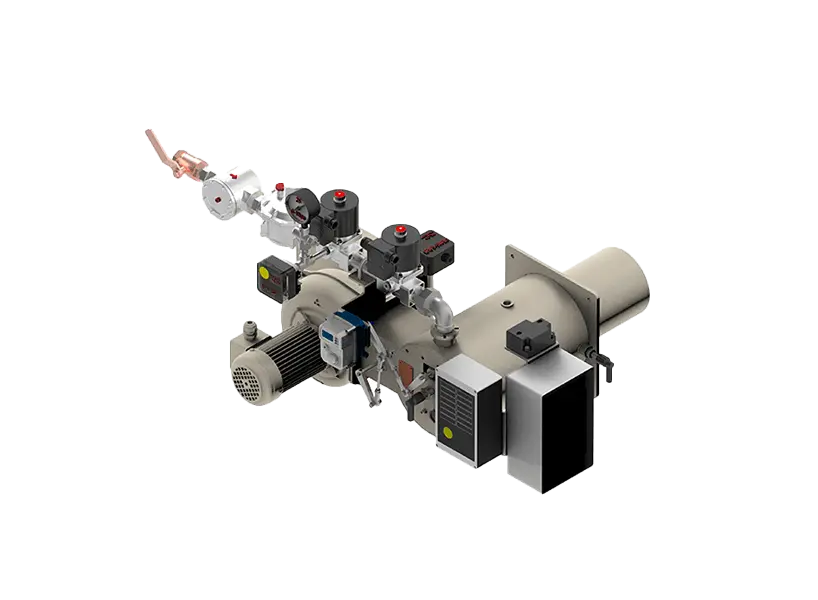
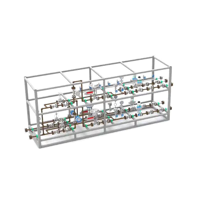
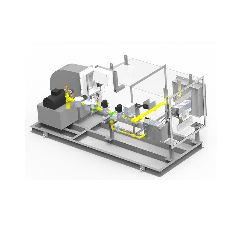
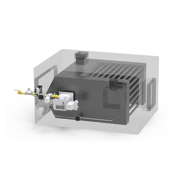
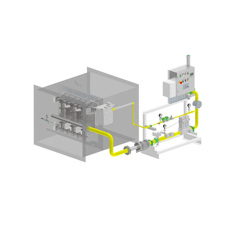
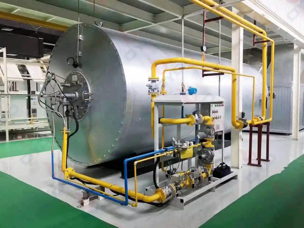
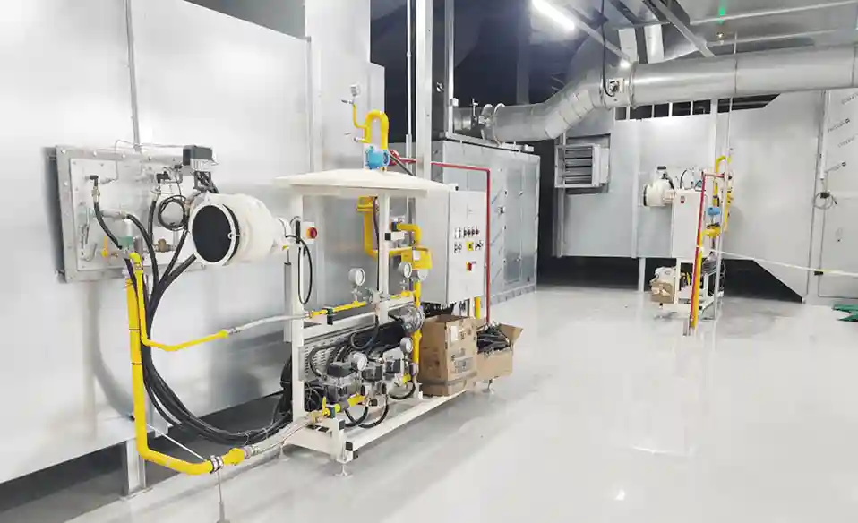
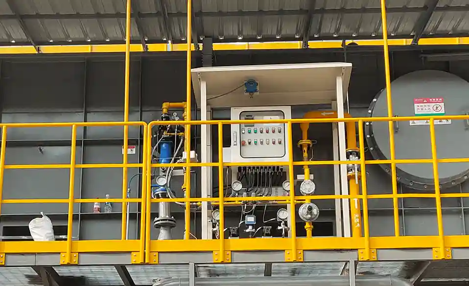
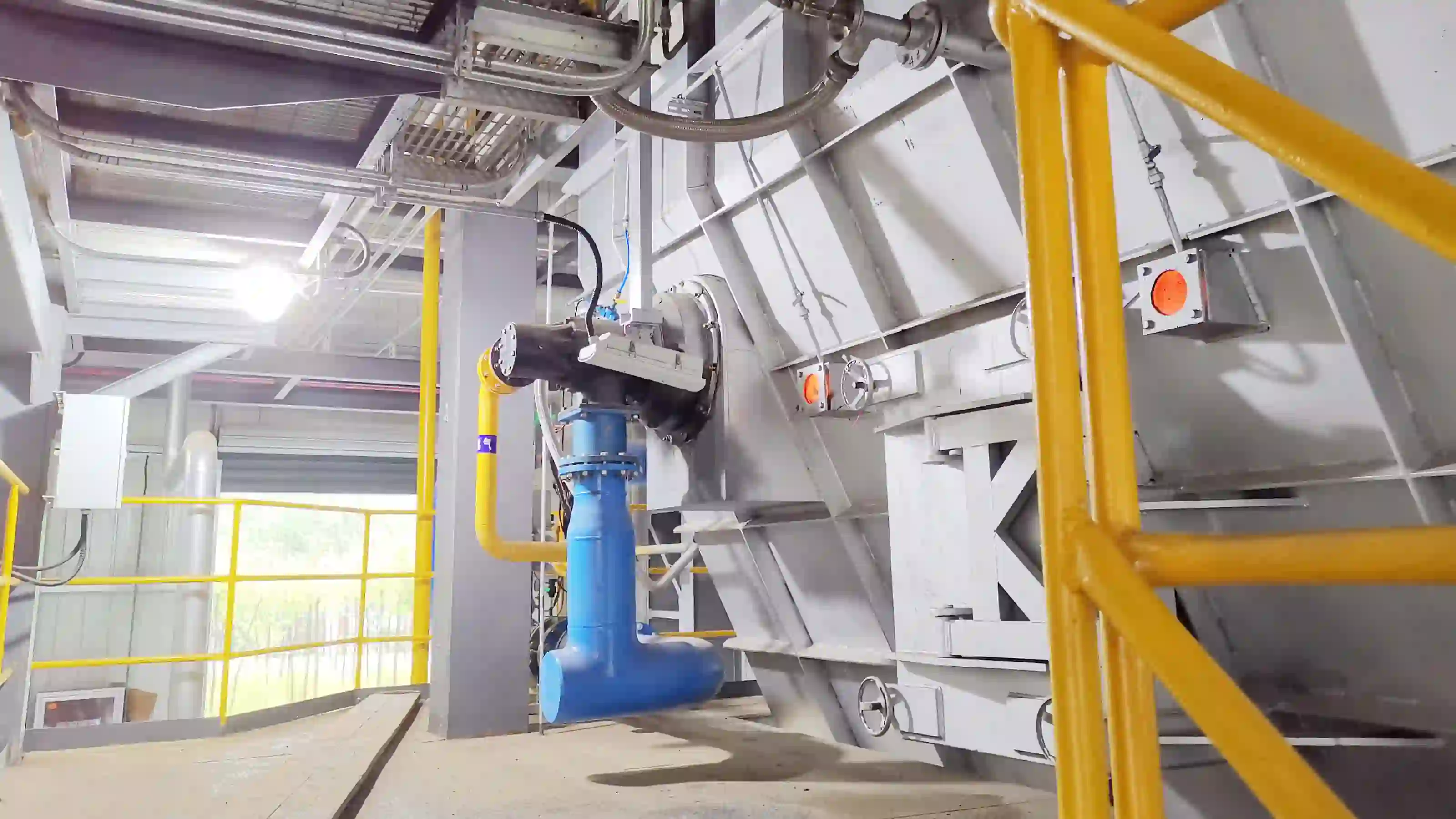
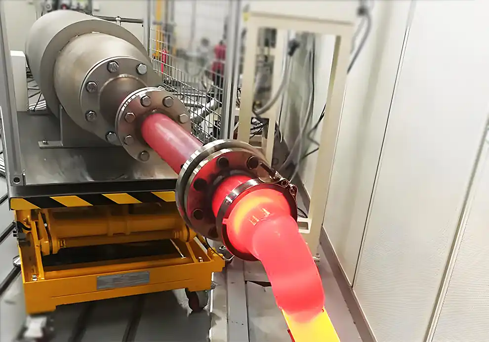
An industrial burner works by precisely controlling the supply of fuel and combustion air, safely igniting the mixture, continuously monitoring the flame, and adjusting combustion output to provide stable, efficient, and safe heat for industrial processes. A complete burner system integrates fuel control, air supply, ignition, flame supervision, safety protection, and automatic control to maintain optimal combustion under varying operating conditions. This precision is achieved through closed-loop feedback from temperature sensors, oxygen analyzers, and flame detectors, which together allow the burner to respond to load changes within seconds while maintaining a consistent excess-air level—typically between 5% and 15% for natural gas—to avoid both incomplete combustion and excessive heat loss.
Industrial burners convert the chemical energy of fuel into controlled thermal energy.
Stable combustion depends on accurate air-fuel ratio control.
Every burner operates through a predefined ignition and safety sequence.
Flame monitoring is essential for safe industrial operation.
Modern industrial burners automatically adjust heat output according to process demand.
The working principle of an industrial burner is based on controlled combustion.
Fuel and combustion air are supplied separately, mixed at the burner head, ignited by an ignition device, and continuously burned under automatic control. The generated flame transfers heat into the furnace or process chamber while the combustion control system continuously adjusts fuel and airflow to maintain stable operation. This control loop typically relies on a combination of ratio regulators, variable-speed drives, and position feedback from air/fuel valves to ensure that the mixture remains near the stoichiometric point across the entire firing range.
Unlike simple open flames, industrial burners are designed to deliver repeatable combustion with high efficiency, low emissions, and reliable safety protection. They incorporate engineered flame stabilization features—such as swirl generators, bluff bodies, or flame retention rings—that anchor the flame in place even when combustion air velocities are high, preventing blow-off or flashback.
The combustion process begins when natural gas or LPG enters the gas train.
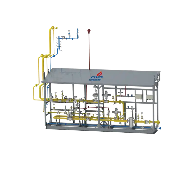
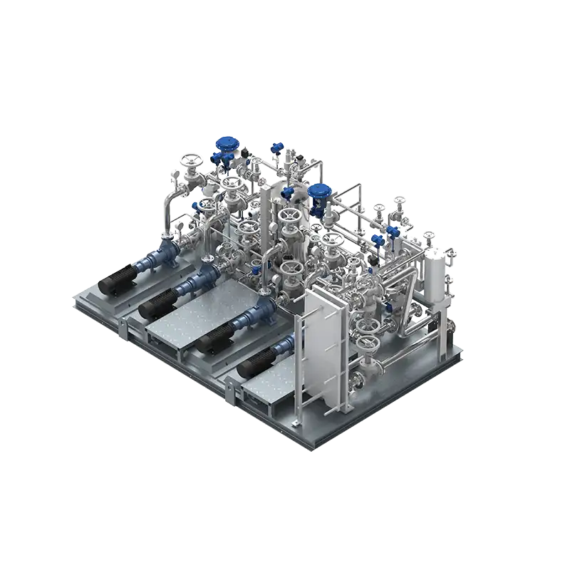
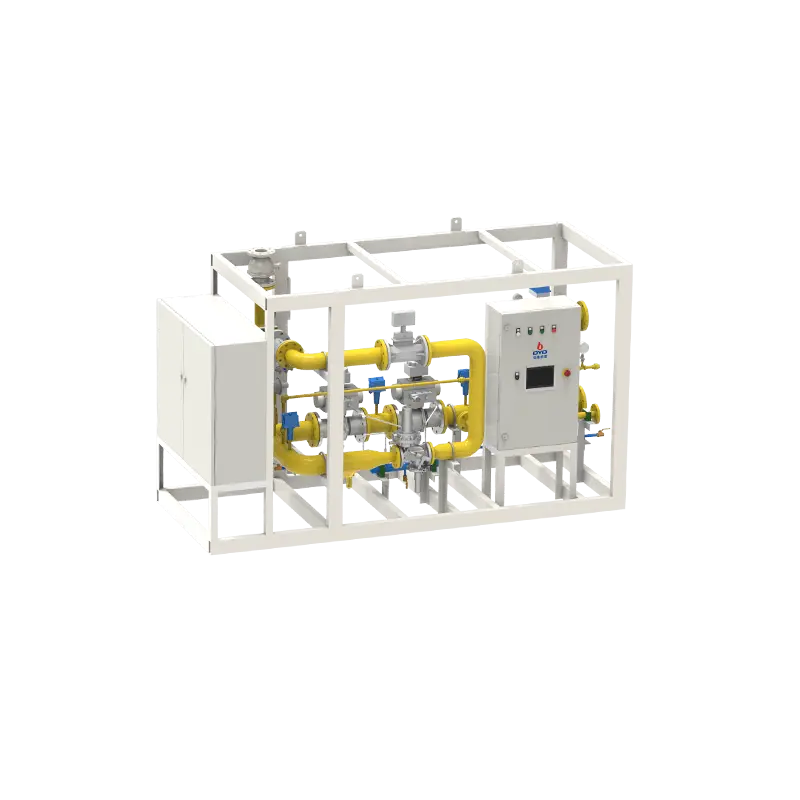
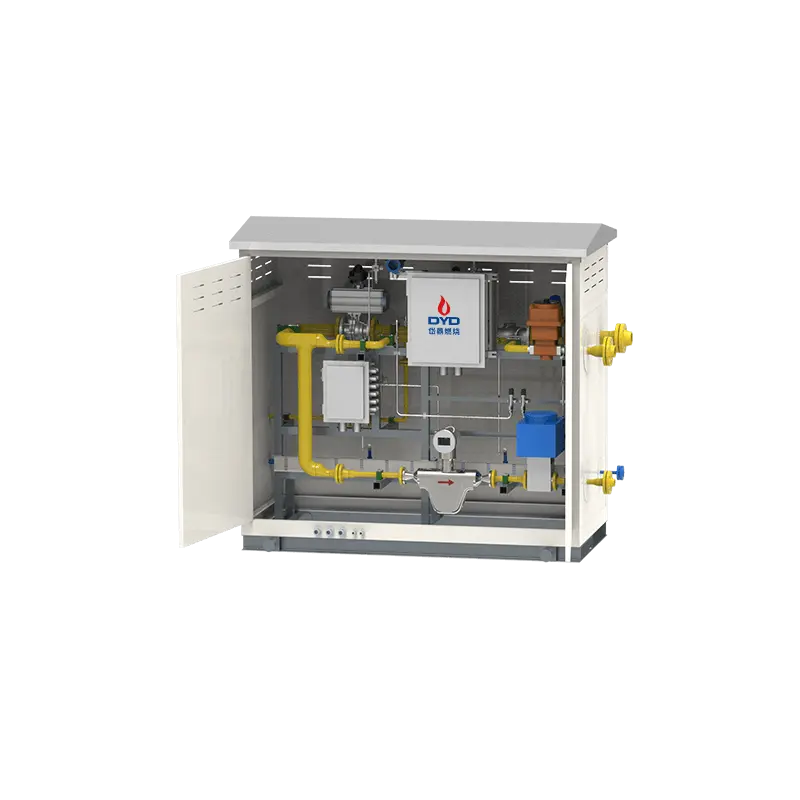
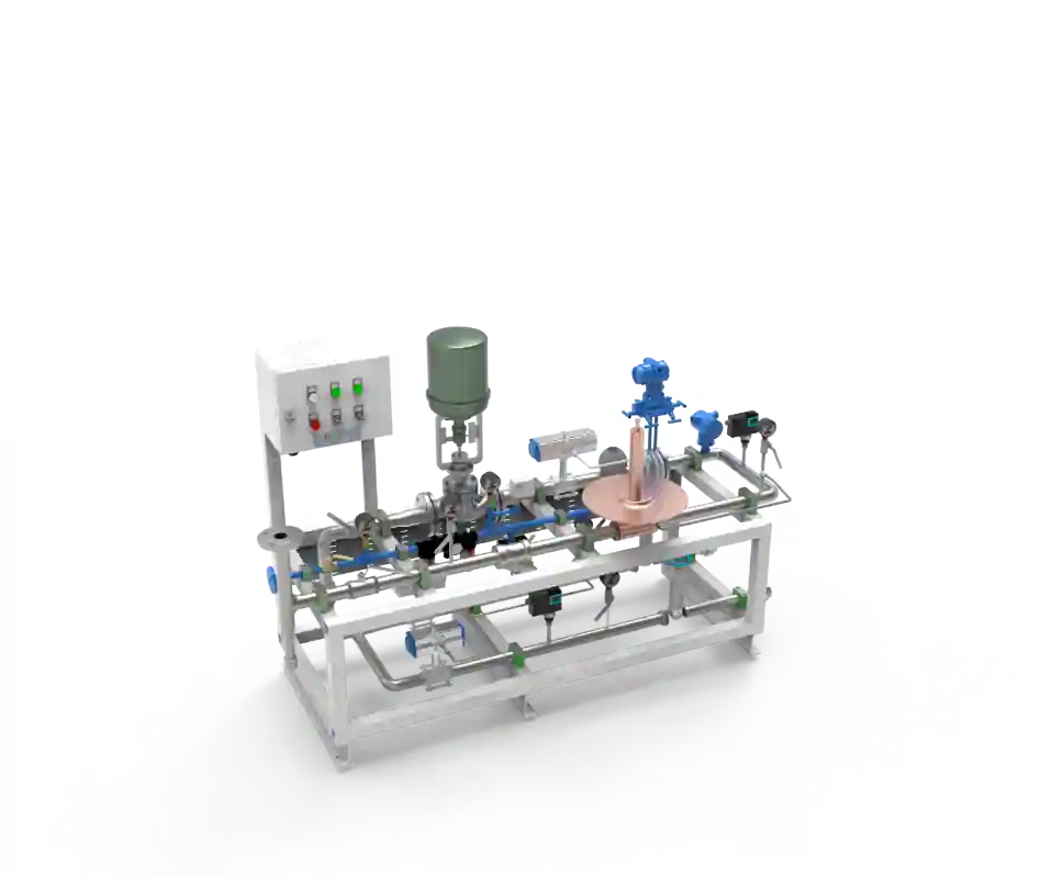
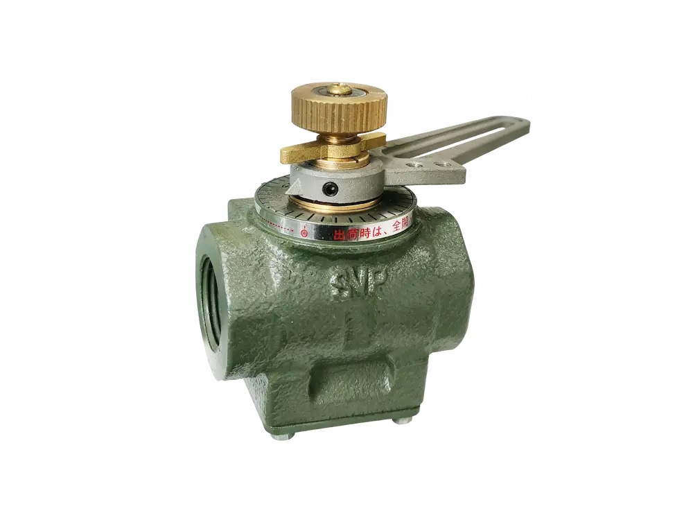
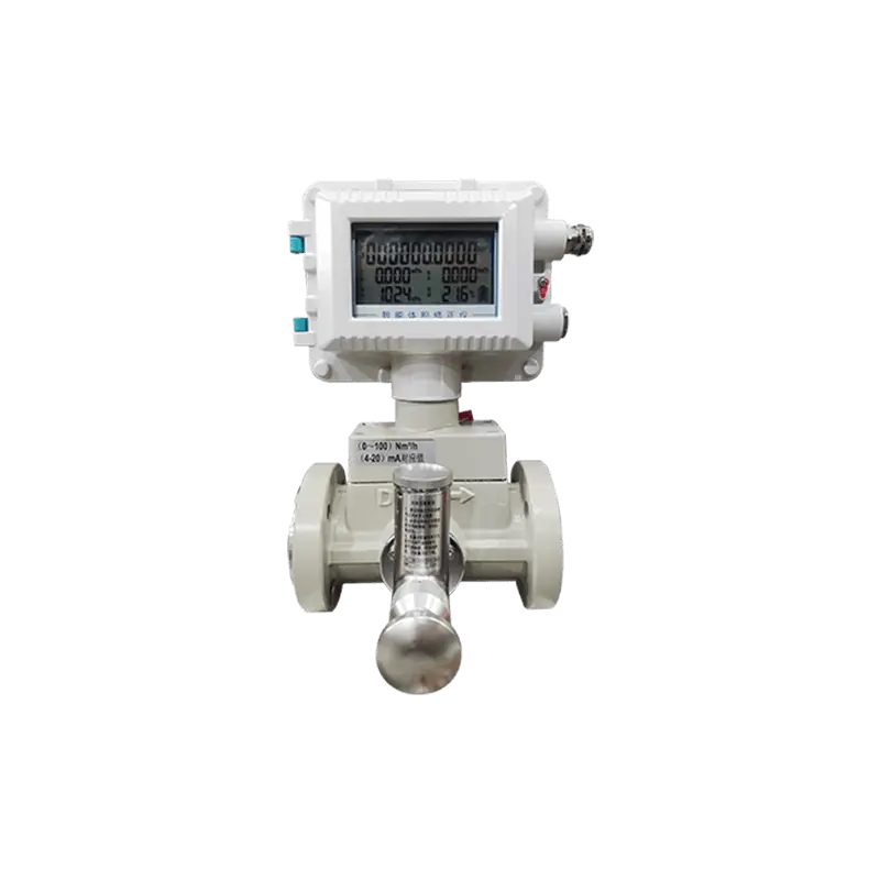
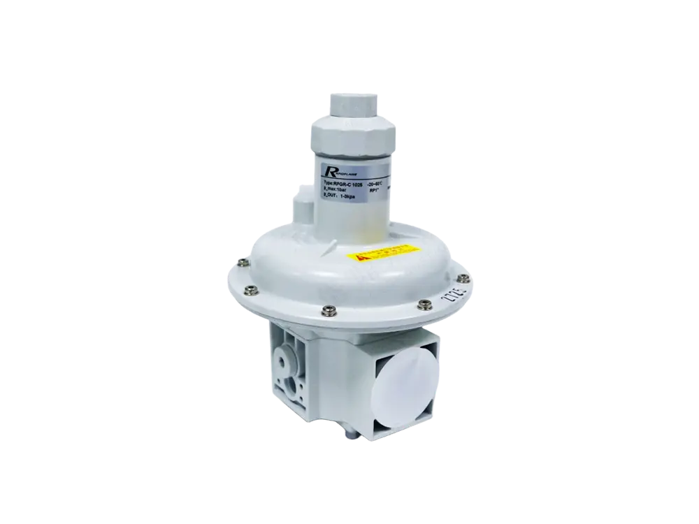
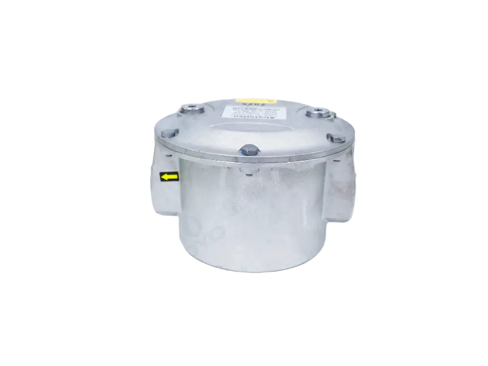
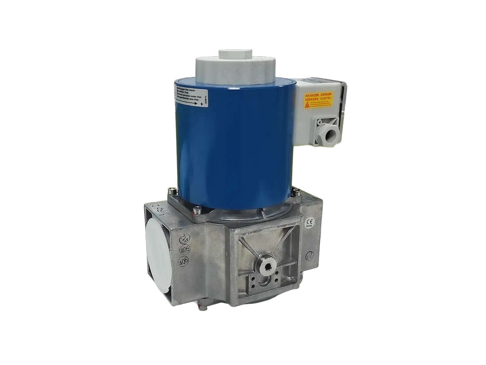
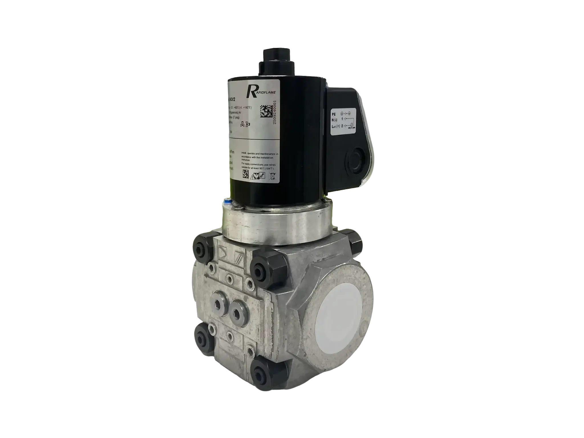
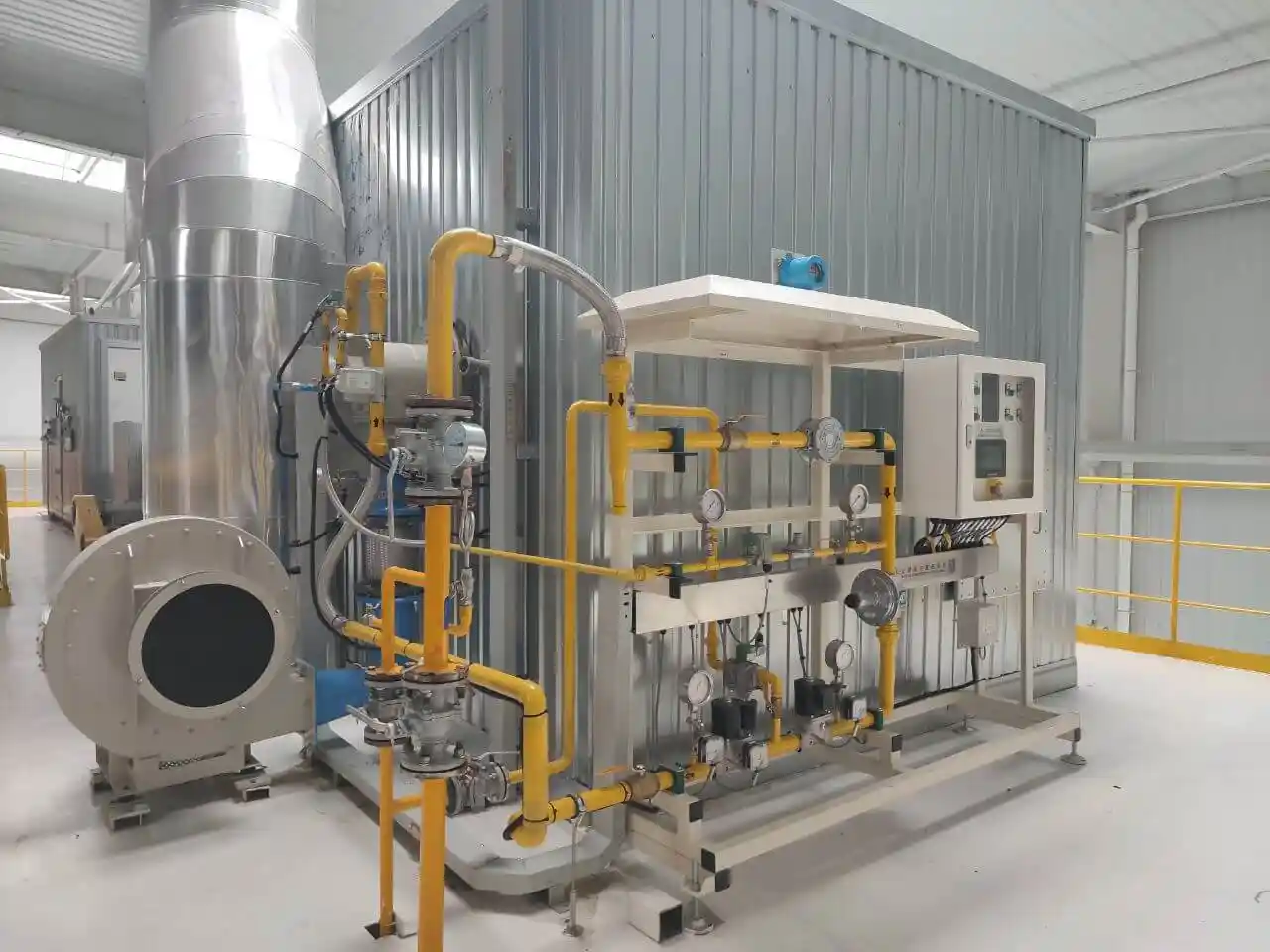
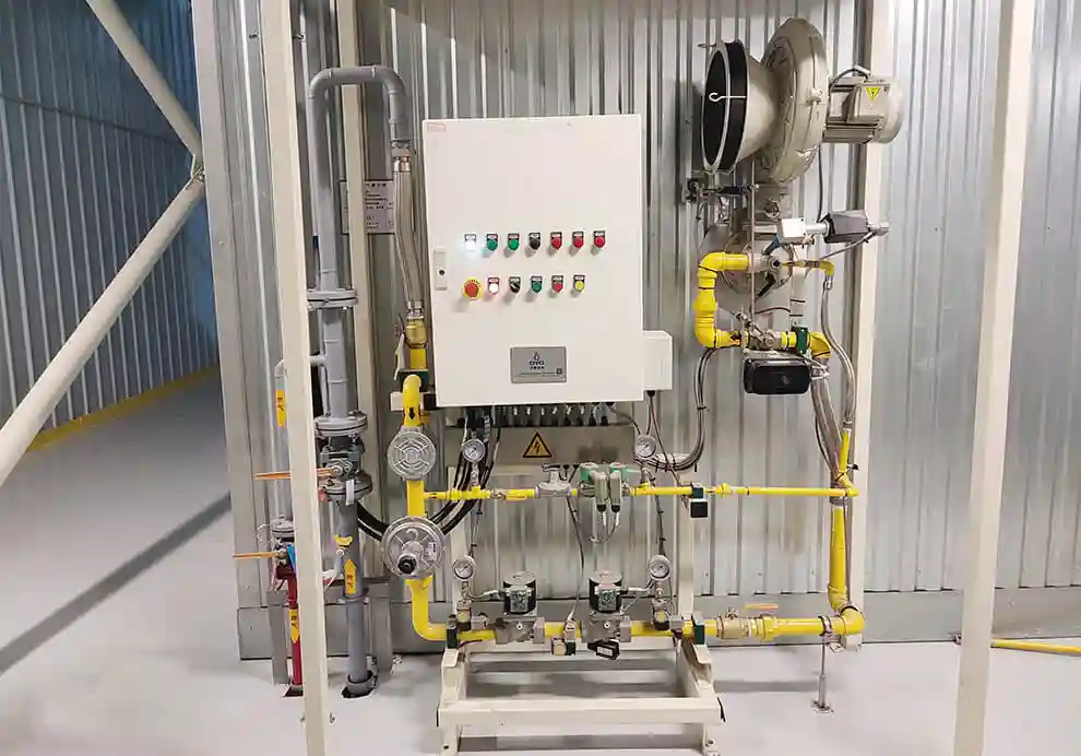
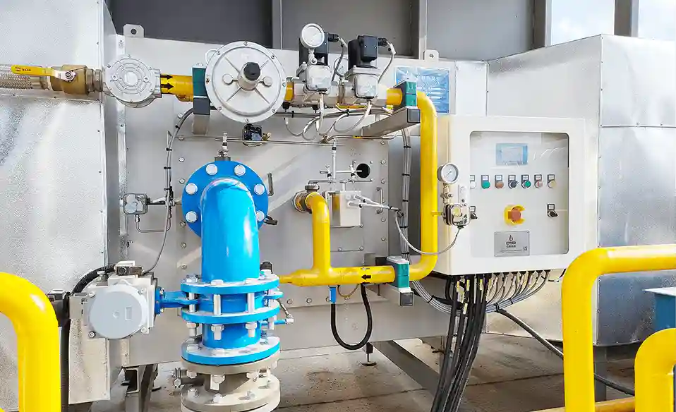
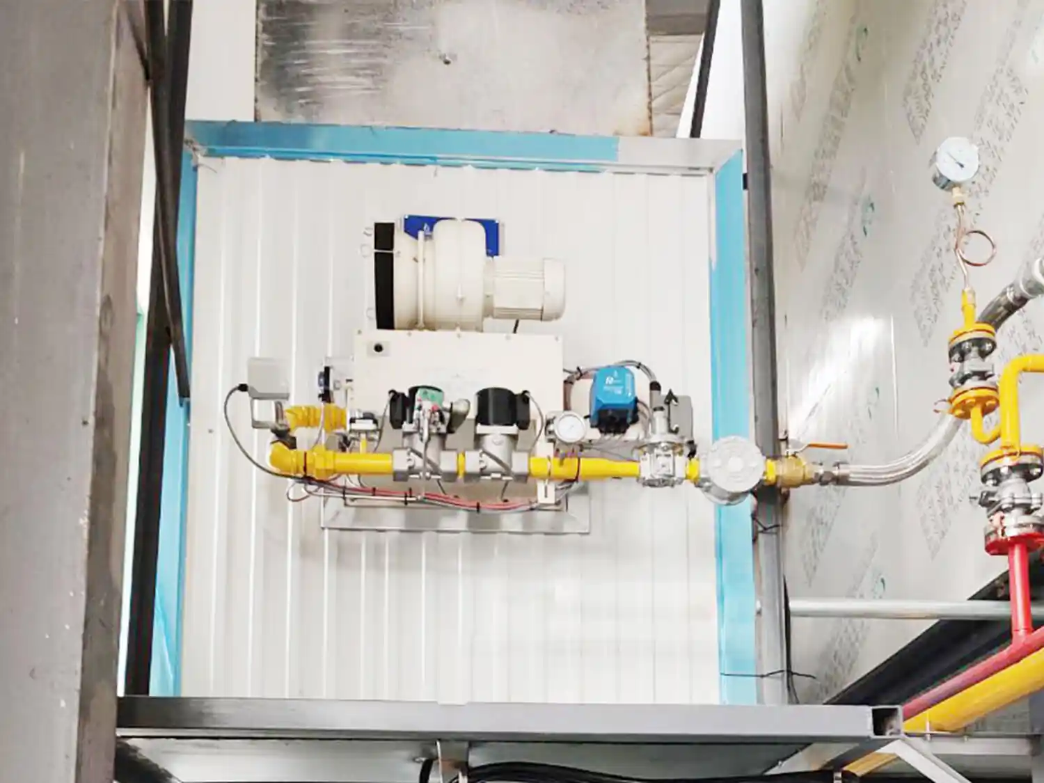
The gas train regulates pressure, filters impurities, controls flow, and includes multiple safety shut-off valves that prevent unintended fuel release. Typical gas train components include a main manual shut-off valve, a pressure regulator (often with a built-in filter), low- and high-pressure switches, two redundant solenoid valves in a double-block-and-bleed arrangement, and a flow metering device such as an orifice plate or a modulating control valve. The regulated gas pressure is usually maintained between 20 and 50 mbar for low-pressure burners, though high-pressure systems may operate at several bar.
At this stage, fuel is prepared but not yet allowed to enter the burner until the purge cycle and all safety interlocks are satisfied.
A combustion air fan supplies fresh air to the burner.
The airflow is carefully controlled according to burner capacity and firing rate. The fan may be a centrifugal or axial type, often driven by an AC motor with a variable-frequency drive (VFD) to match air volume precisely to the fuel flow at every firing position. In forced-draft designs, the fan pushes air into the burner, overcoming furnace backpressure; in induced-draft systems, the fan is located downstream and pulls flue gases, maintaining a slight negative pressure in the combustion chamber.
Proper airflow is critical because too little air causes incomplete combustion, while too much air reduces thermal efficiency. For natural gas, the theoretical (stoichiometric) air requirement is about 9.5–10.5 m³ of air per m³ of gas; actual operation uses 5–20% excess air to ensure complete oxidation without excessive heat loss.
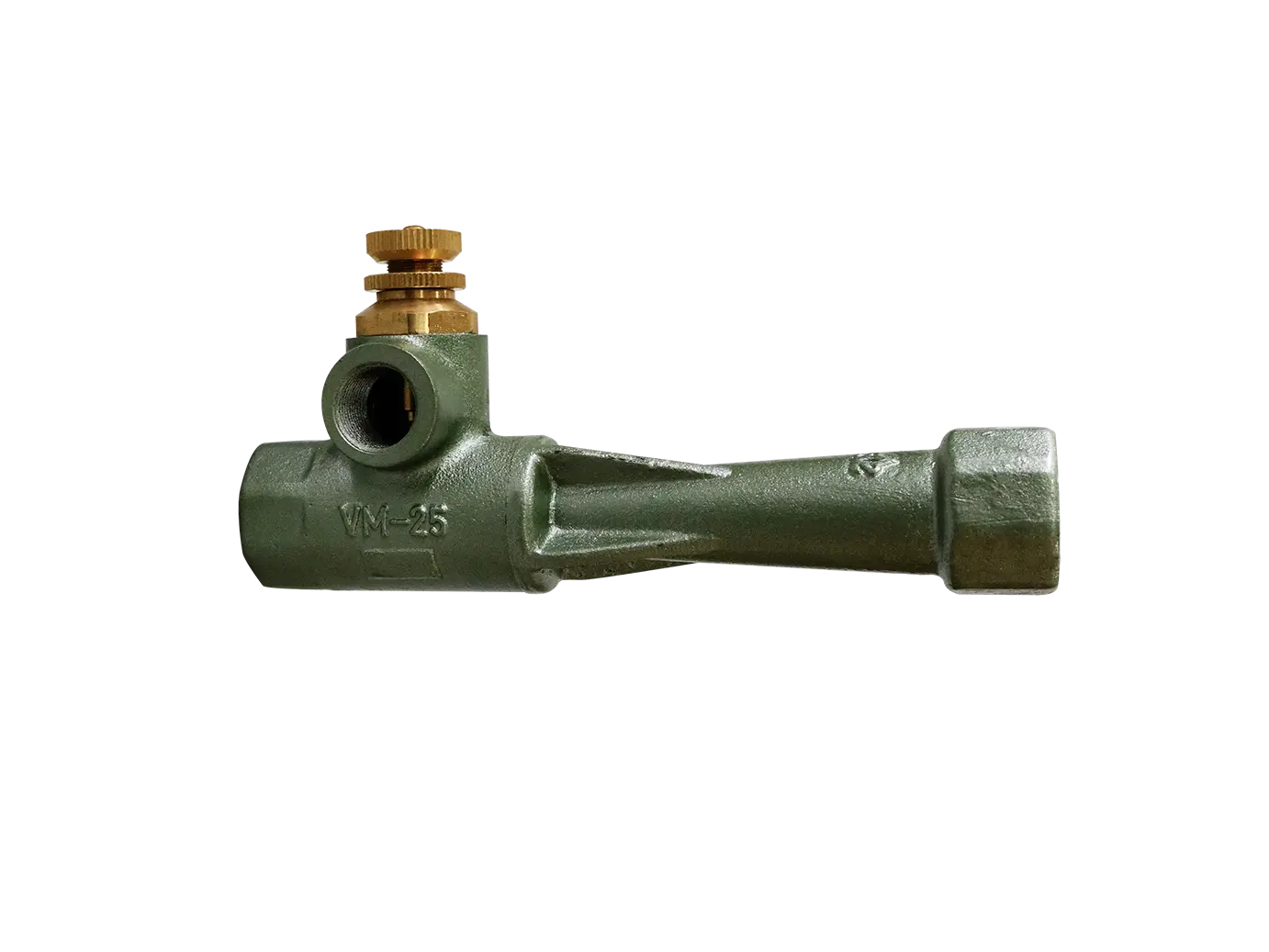
Inside the burner head, fuel and combustion air are mixed in the proper proportion.
The burner design determines:
Mixing intensity
Flame shape
Flame length
Flame velocity
Flame stability
Different mixing strategies exist: premix burners combine fuel and air before they exit the nozzle, producing short, intense flames with very low excess air; nozzle-mix burners keep fuel and air separate until the point of ignition, allowing longer, more luminous flames that are better for radiant heat transfer; staged burners introduce secondary air downstream to control flame temperature and reduce NOx formation. The choice of mixing method directly influences the combustion efficiency and the pollutant profile.
Efficient mixing produces complete combustion and minimizes pollutant formation. Turbulent mixing, enhanced by swirl vanes or baffles, ensures that every fuel molecule encounters sufficient oxygen within the short residence time of the flame.
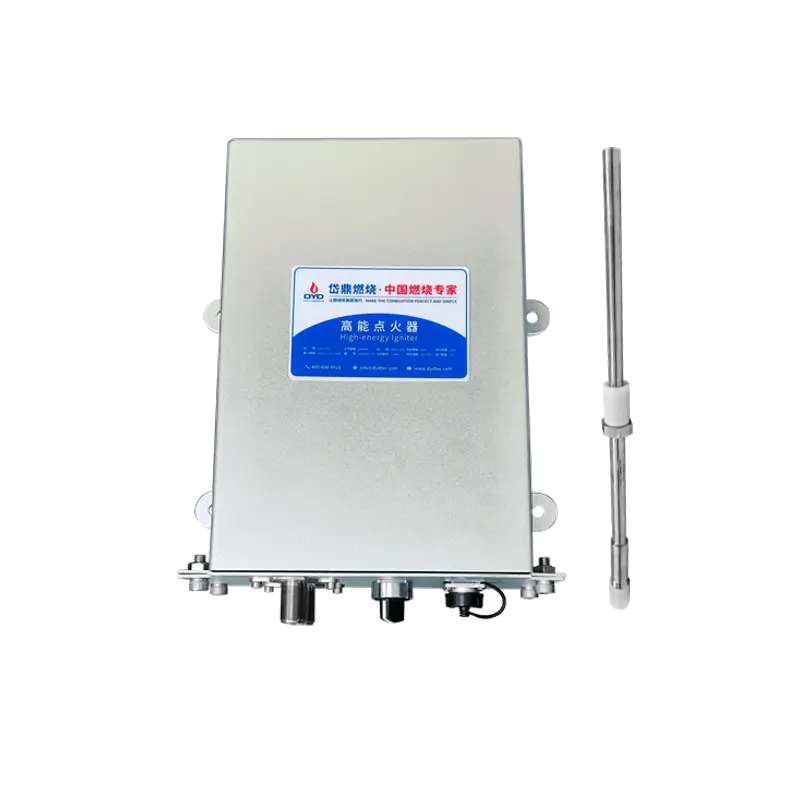
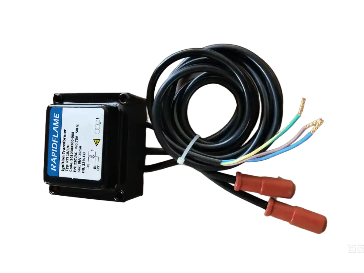
After all safety conditions are verified, the ignition transformer generates a high-voltage spark.
The pilot flame or direct spark ignites the combustible mixture. Most industrial burners use a separate pilot burner that provides a small, stable flame—often fueled by the same gas—which then ignites the main flame. The spark energy typically ranges from 4 to 20 Joules, sufficient to reliably light the mixture even under cold start or high-velocity conditions. The ignition period is timed (usually 3–5 seconds) and is interlocked with the flame detector to ensure that ignition has occurred before the main fuel valve opens fully.
Once flame detection confirms successful ignition, the burner automatically enters normal operation.
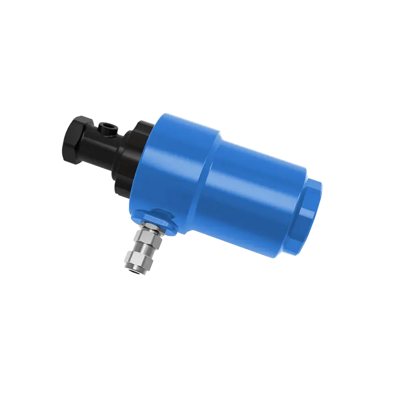
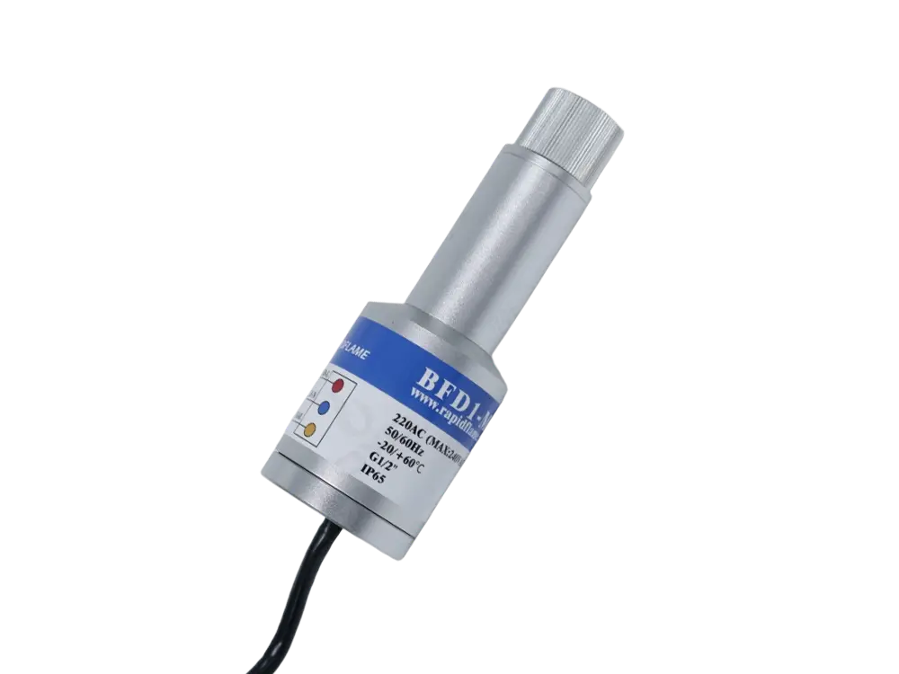
During operation, a flame detector continuously verifies that combustion is occurring.
Common flame detection technologies include:
UV flame detectors – sense the ultraviolet radiation emitted by the flame, responding within milliseconds and offering excellent discrimination against hot refractory background.
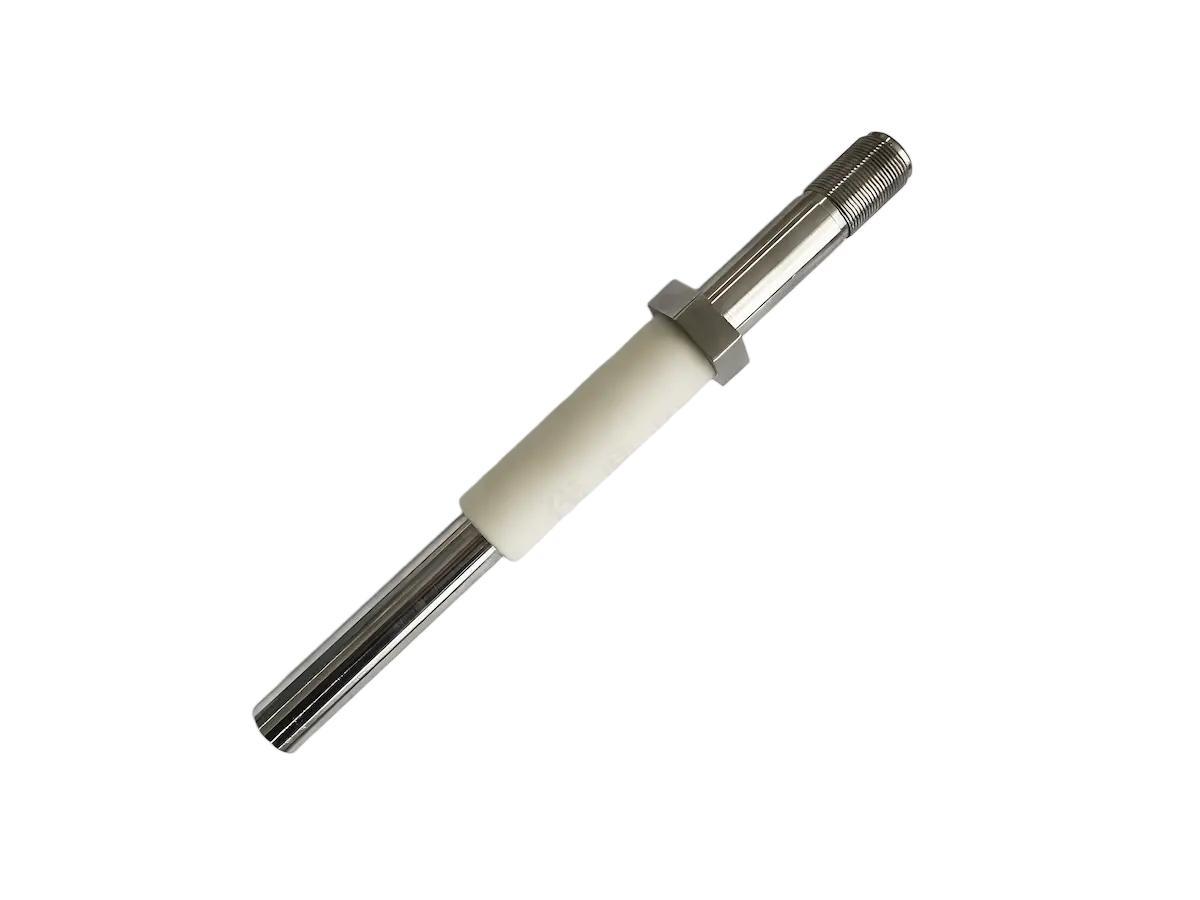
Flame rods (ionization) – use the conductive property of the flame itself; a rod immersed in the flame detects the rectified current (typically a few microamps) that confirms flame presence. This method is simple, reliable, and widely used for smaller burners.
Infrared flame sensors – detect the flicker frequency of the flame in the infrared spectrum, suitable for applications where UV interference is present.
If the flame disappears unexpectedly, the burner management system immediately closes all fuel valves to prevent dangerous gas accumulation. The shutdown response time is normally less than 1 second, meeting international safety standards such as NFPA 86 or EN 746.
Modern industrial burners do not operate at a fixed output.
Instead, the control system continuously adjusts:
Fuel flow
Airflow
Air-fuel ratio
Burner firing rate
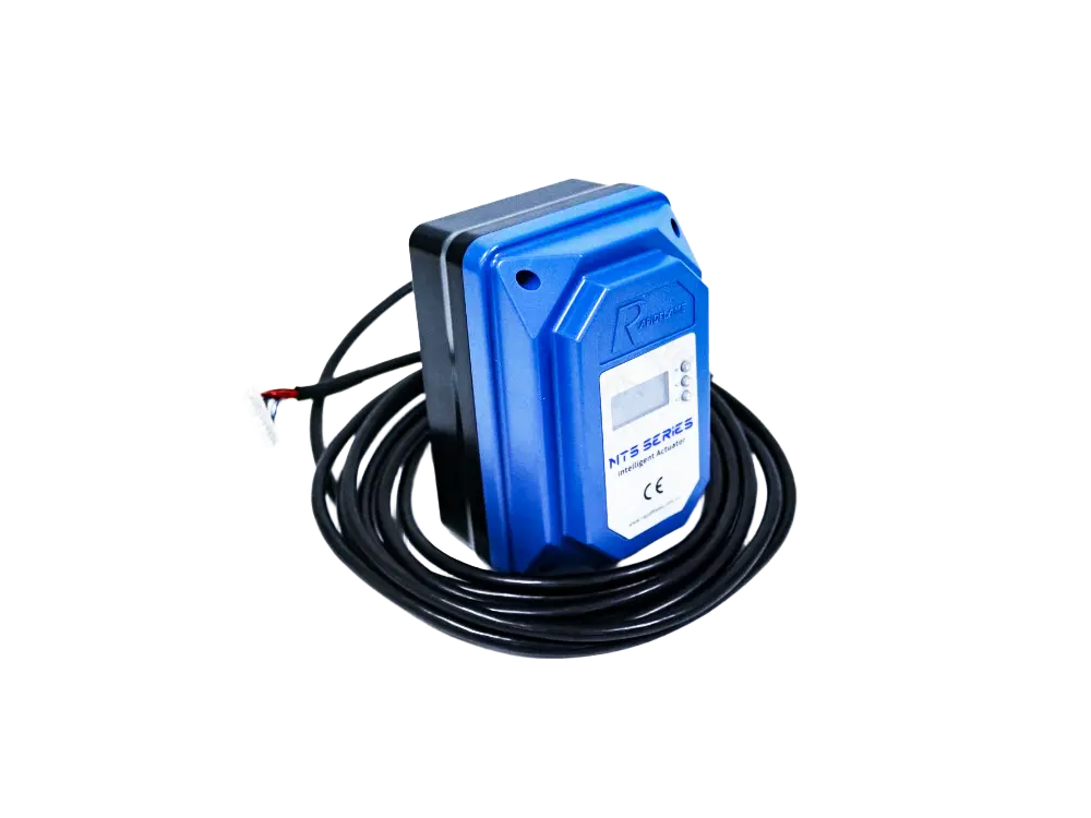
These adjustments maintain the required furnace temperature while maximizing efficiency and reducing emissions. The control strategy can be as simple as a high-low-off system (two firing stages) or as sophisticated as fully modulating control, where a PID controller continuously varies the fuel valve and the air damper (or VFD) to track the setpoint. Advanced systems also incorporate cross-limiting logic, which ensures that air flow always leads when increasing firing rate and fuel flow leads when decreasing, preventing transient rich mixtures that could cause soot or CO spikes.
The flame releases thermal energy into the furnace chamber.
Heat is transferred through:
Radiation – dominant at flame temperatures above 800 °C, where energy is emitted as electromagnetic waves directly to the furnace walls and the load.
Convection – the hot combustion gases circulate and transfer heat by direct contact with the product or the heat exchanger surfaces.
Hot gas circulation – in some designs, recirculated flue gases are mixed with the flame to moderate temperature and improve heat distribution, which also helps reduce thermal NOx.
The heated chamber then transfers energy to the product or material being processed. The overall heat transfer rate depends on flame emissivity, gas velocity, furnace geometry, and the thermal properties of the load.
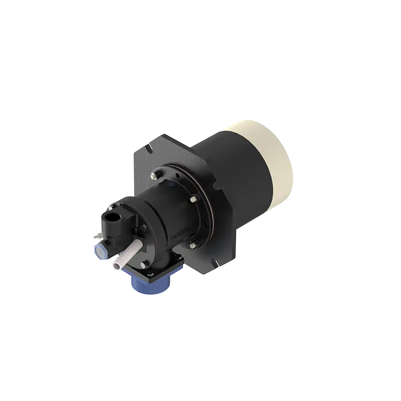
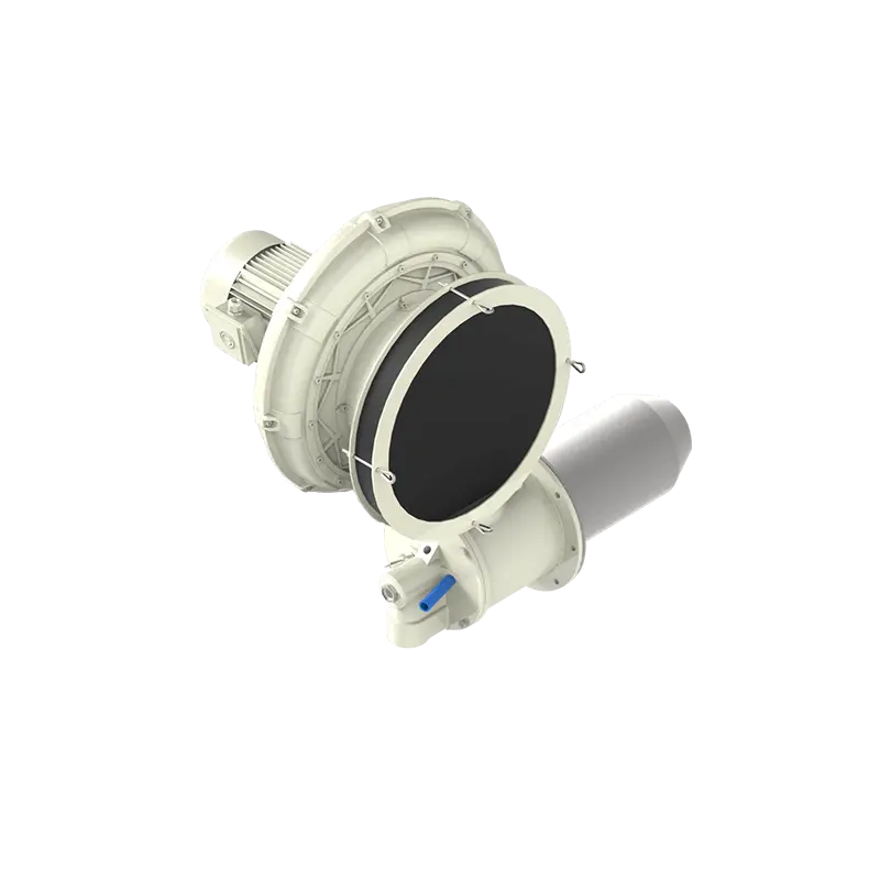
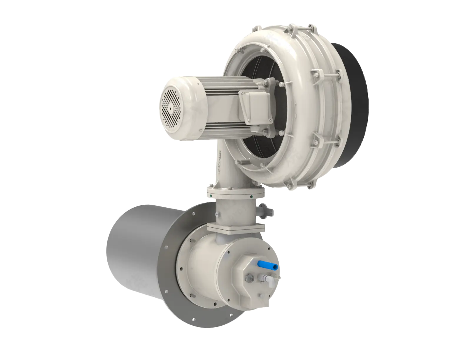
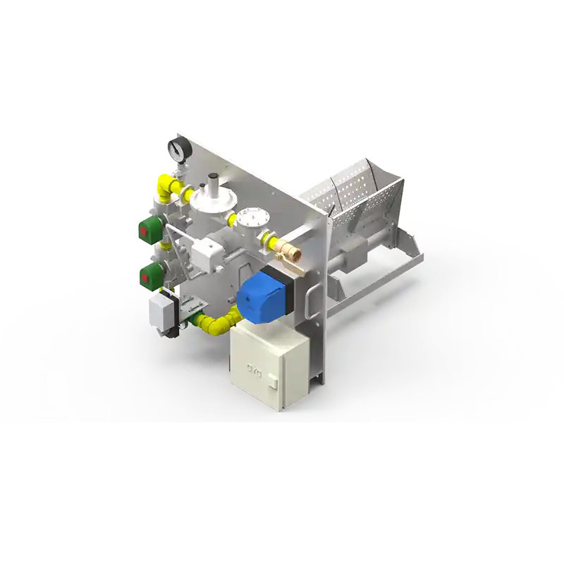
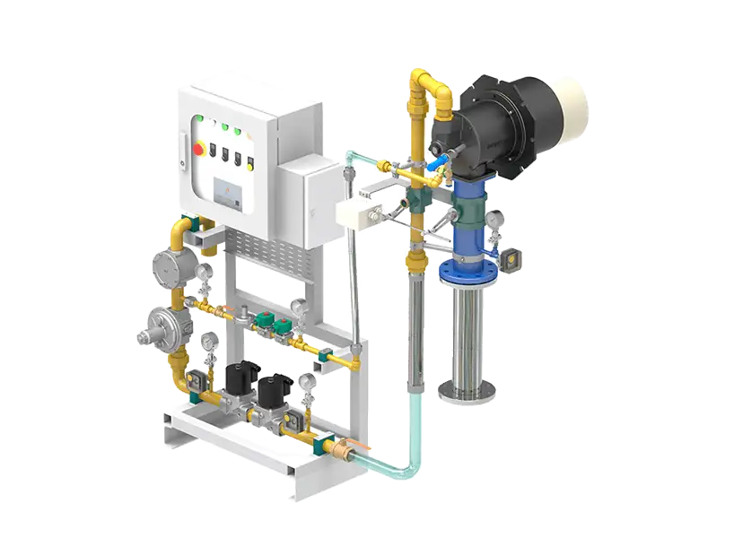
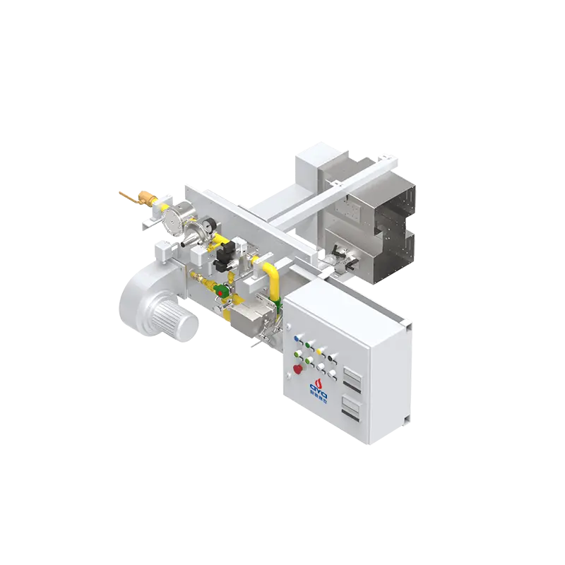
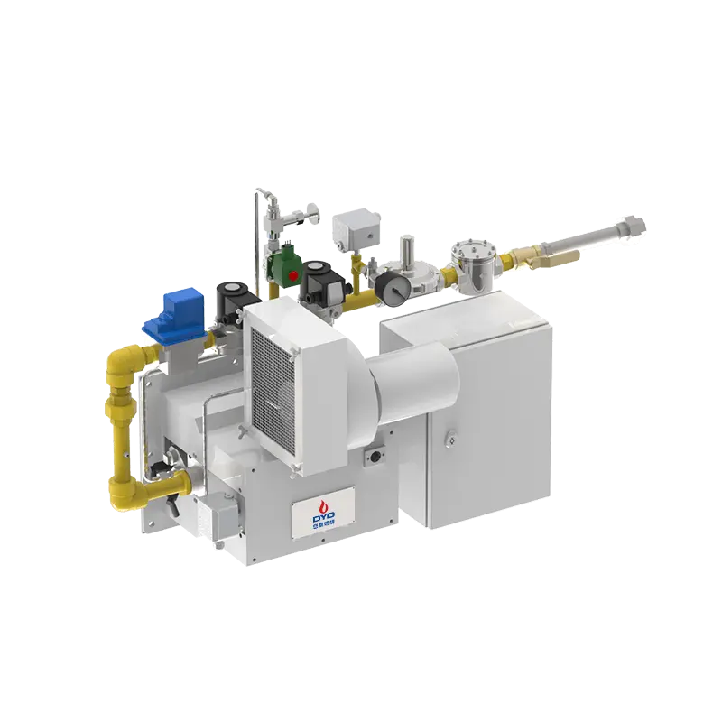
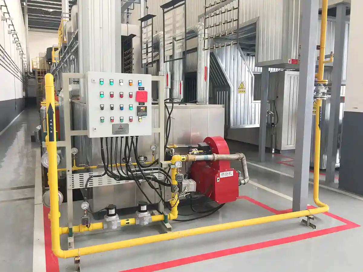
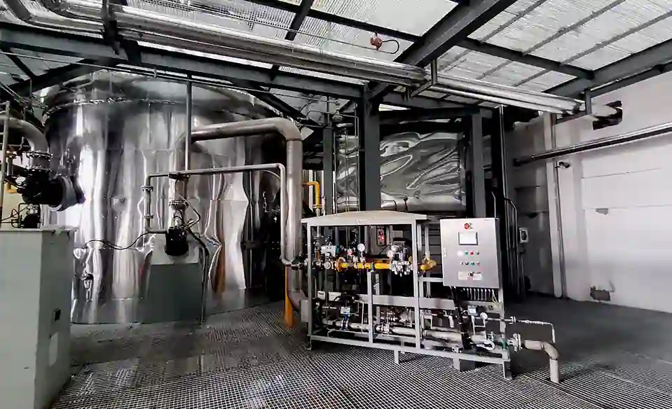
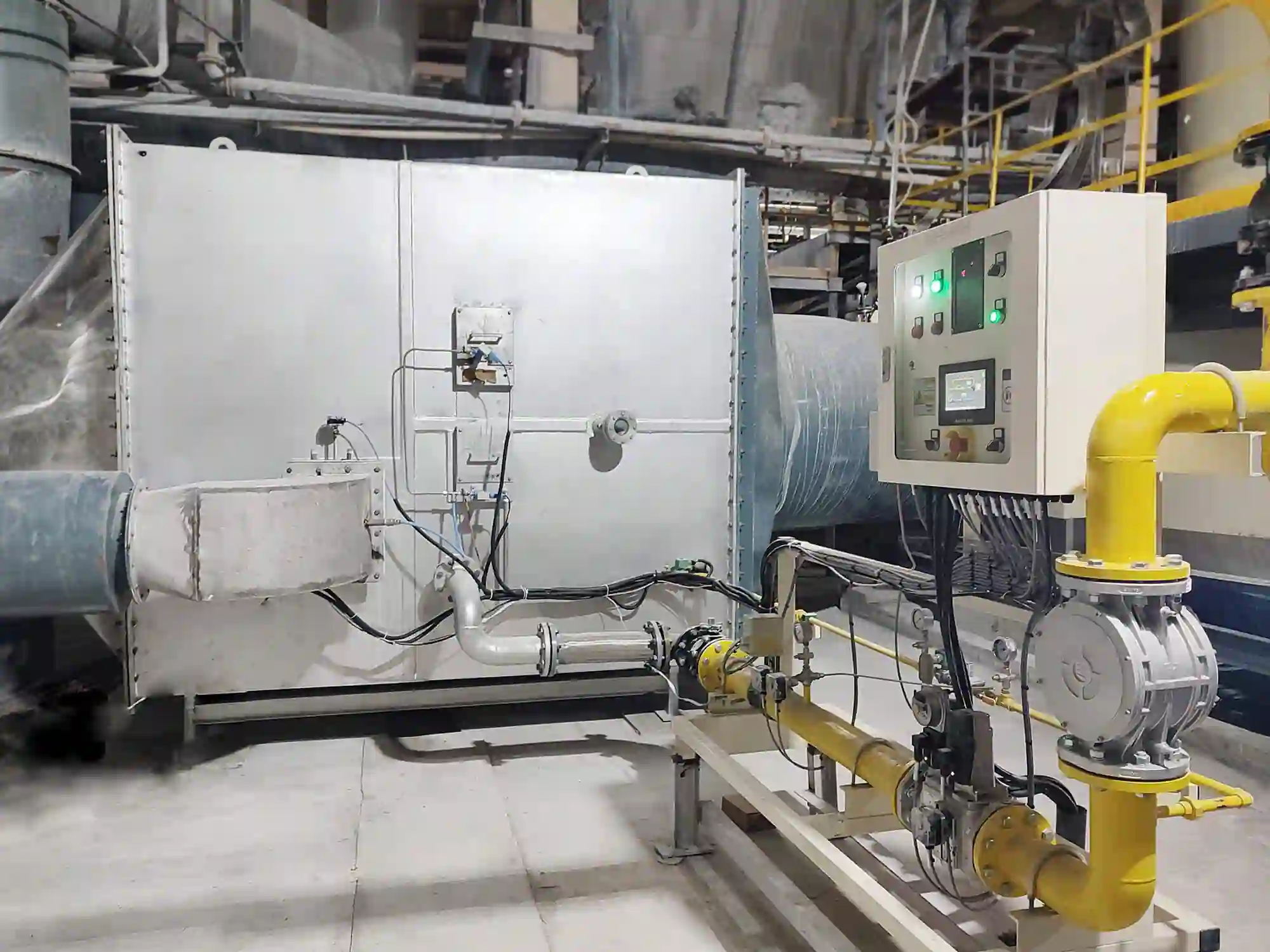
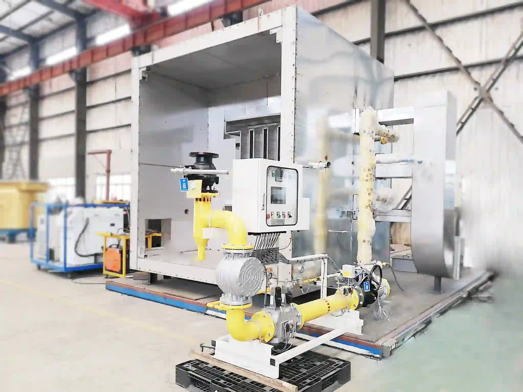
A complete industrial burner consists of several integrated systems.
Fuel Supply System – Controls fuel pressure, filtration, shut-off, and flow regulation. It ensures that the gas is clean, at the correct pressure, and delivered in precise quantities.
Combustion Air System – Provides the required combustion air for complete fuel oxidation. This includes the fan, air filter, damper or VFD, and air pressure switches.
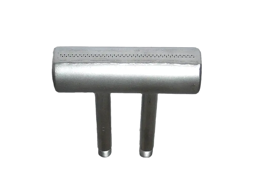
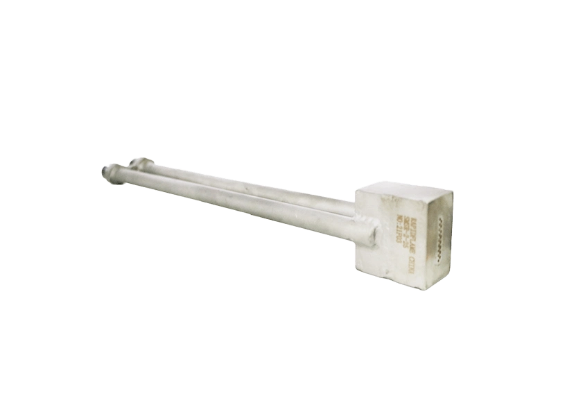
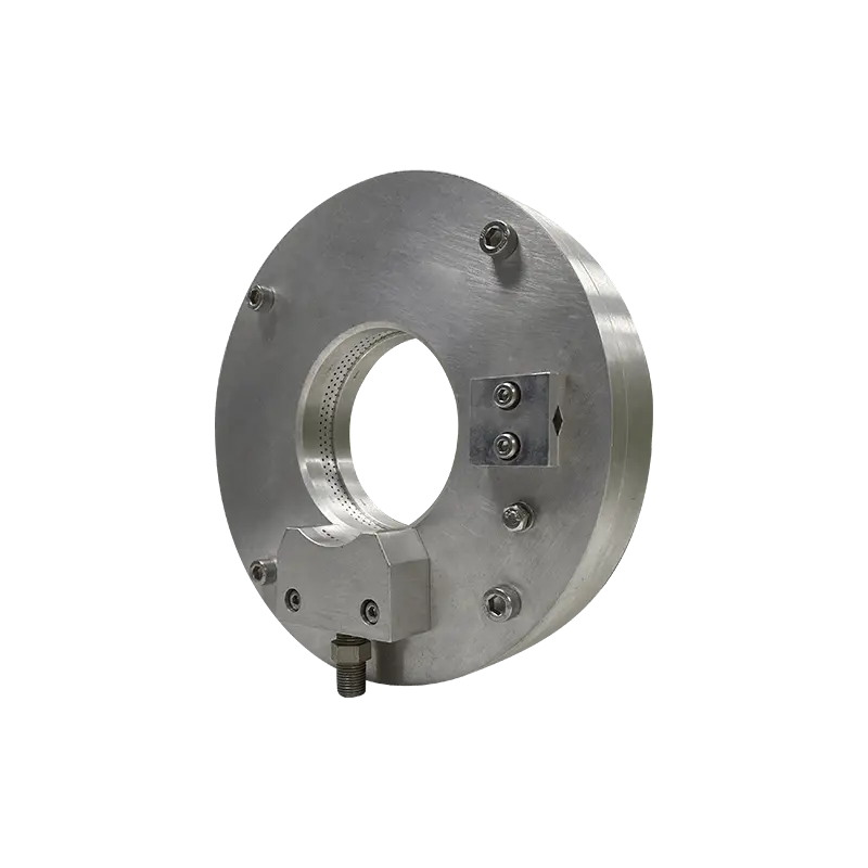
Burner Head – Mixes fuel and air while shaping the flame according to process requirements. Its internal geometry determines the flame characteristics and stability margin.
Ignition System – Generates a reliable ignition source during startup. It includes the transformer, ignition cable, spark plug, and pilot fuel line.
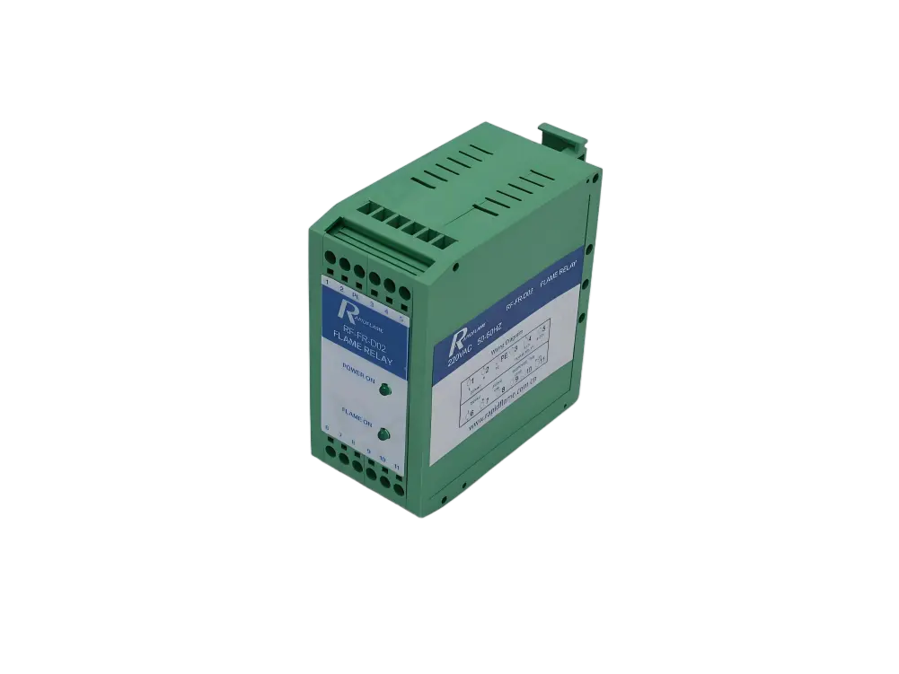
Flame Supervision System – Monitors flame presence throughout burner operation, using one or more detectors with self-checking capabilities.
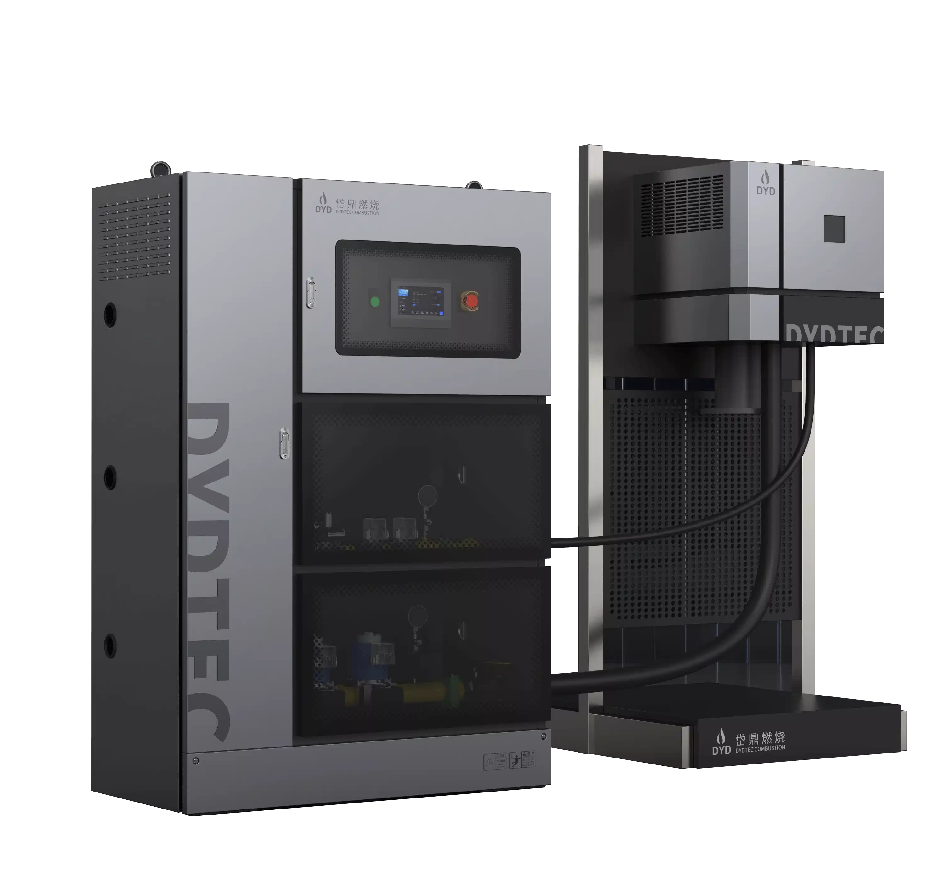
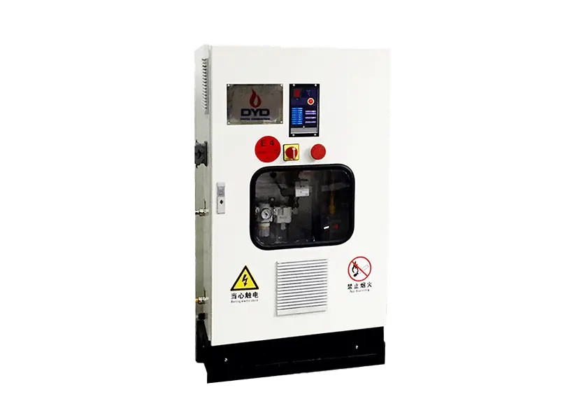
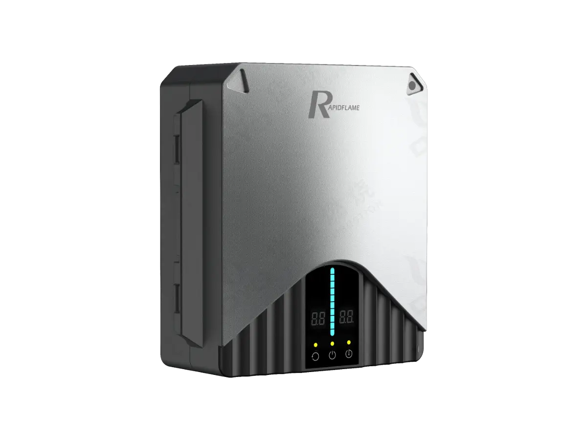
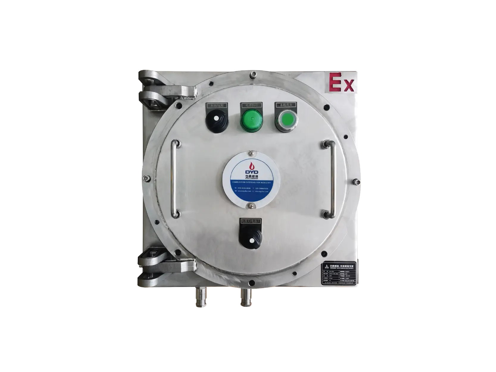
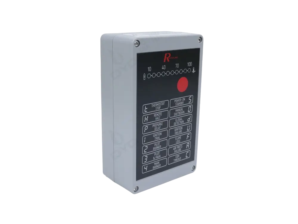
Burner Management System (BMS) – Coordinates startup, shutdown, combustion control, fault detection, and safety interlocks. The BMS is the brain of the burner, executing a pre-programmed sequence and interfacing with the plant’s distributed control system (DCS) or PLC.
These systems operate together to ensure stable combustion and safe industrial operation. Any failure in one subsystem triggers a safe shutdown, and the BMS logs the fault for diagnostics.
Efficient combustion depends on maintaining the correct proportion of fuel and air.
If insufficient air is supplied:
Incomplete combustion occurs
Fuel consumption increases
Carbon monoxide may form
Flame stability decreases
If excessive air is supplied:
Heat losses increase
Flame temperature decreases
Thermal efficiency drops
Accurate air-fuel ratio control is therefore one of the most important factors affecting burner performance. The ideal ratio, known as the stoichiometric ratio, depends on the fuel composition—for natural gas, about 9.5 volumes of air per volume of gas. In practice, a small excess of air (5–15%) is used as a safety margin, but even 1% extra excess air can reduce efficiency by roughly 0.1–0.2%. State-of-the-art burners use oxygen trim control, where a flue-gas oxygen sensor provides feedback to fine-tune the ratio in real time, compensating for changes in ambient temperature, humidity, or fuel calorific value.
Stable combustion requires several conditions to be satisfied simultaneously:
Constant fuel pressure
Stable combustion airflow
Proper burner head design
Reliable ignition
Continuous flame monitoring
Responsive automatic control
Appropriate furnace pressure
Any disturbance to these conditions may reduce combustion quality or cause flame instability. For example, a sudden drop in fuel pressure can lean out the mixture, risking flame lift-off, while a blocked air inlet can enrich the mixture, leading to sooting and potential CO emissions. Modern burners incorporate pressure switches and differential pressure transmitters to detect such deviations and either correct them (by adjusting the control outputs) or shut down the system if safe operation cannot be guaranteed.
Industrial burners incorporate multiple layers of protection, including:
Automatic ignition sequence with timed purging
Flame failure protection (fuel shut-off within 1 second on flame loss)
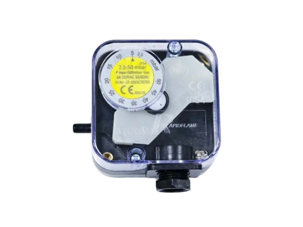
Gas pressure monitoring (low and high pressure switches)
Air pressure monitoring (to confirm sufficient air supply before ignition)
Safety shut-off valves (double-block-and-bleed for leak-tight closure)
Emergency shutdown logic (manual and automatic trip)
Burner Management System (BMS) with hardware and software interlocks
These features reduce operational risks and help ensure compliance with industrial safety standards such as NFPA 86 (Ovens and Furnaces), EN 746 (Industrial Thermoprocessing Equipment), and ISO 13577. Regular testing of the safety functions, including valve proving tests and flame-detector response checks, is recommended to maintain the integrity of the protection system.
Not always. Some burners operate continuously, while others modulate or cycle according to process demand and temperature control requirements. In modulating operation, the flame is maintained continuously but at varying heat input; in cycling operation, the burner turns on and off to maintain the setpoint within a hysteresis band. Continuous modulation is generally preferred for processes that require tight temperature control and when rapid thermal cycling would stress the refractory.
Yes. Most modern industrial burners use proportional or fully modulating control systems that automatically adjust firing rate based on process conditions. These systems receive a 4–20 mA or digital signal from a temperature controller, and the BMS or standalone ratio controller positions the fuel valve and air damper/motor accordingly. Some advanced systems also incorporate model-based predictive control to anticipate load changes and minimize overshoot.
Flame monitoring immediately detects flame failure. If combustion stops unexpectedly, the burner management system shuts off the fuel supply to prevent unburned gas from accumulating inside the furnace. Without this safeguard, unburned fuel could form an explosive mixture, leading to a deflagration or even a furnace explosion. Flame monitoring is therefore mandatory for any industrial burner by all major safety codes.
Combustion efficiency is influenced by burner design, air-fuel ratio, flame stability, furnace insulation, heat transfer efficiency, and combustion control accuracy. The most direct measure is the flue-gas composition—specifically the oxygen and carbon monoxide content—and the stack temperature. A well-tuned burner with low excess air and high heat recovery (e.g., using a recuperator) can achieve efficiency above 95% (lower heating value basis). Other factors include the fuel type, ambient air temperature, and the load factor of the furnace.
An industrial burner is far more than a simple ignition device. It is an integrated combustion system that combines fuel delivery, combustion air management, ignition, flame supervision, automatic control, and safety protection into a coordinated process.
Understanding how an industrial burner works enables engineers, OEM equipment manufacturers, and plant operators to improve combustion efficiency, reduce emissions, enhance temperature uniformity, and achieve safer, more reliable industrial heating performance.
DYDTEC Combustion specializes in industrial gas burners and complete combustion systems for OEM equipment manufacturers and industrial heating applications.
Our engineering solutions are widely used in ceramic kilns, aluminum melting furnaces, heat treatment furnaces, industrial drying systems, hot air generators, thermal oxidizers (RTO), and other customized industrial heating equipment.
Our expertise includes:
Industrial gas burners
Low NOx combustion technology
Burner Management Systems (BMS)
Combustion system integration
Energy-efficient combustion optimization
OEM burner customization
Technical support for furnace manufacturers
For more technical resources, engineering insights, and combustion system knowledge, explore the DYDTEC Combustion Knowledge Center.